Project Gutenberg's Hawkins Electrical Guide v. 6 (of 10), by Hawkins

This eBook is for the use of anyone anywhere in the United States and most
other parts of the world at no cost and with almost no restrictions
whatsoever.  You may copy it, give it away or re-use it under the terms of
the Project Gutenberg License included with this eBook or online at
www.gutenberg.org.  If you are not located in the United States, you'll have
to check the laws of the country where you are located before using this ebook.


Title: Hawkins Electrical Guide v. 6 (of 10)
       Questions, Answers, & Illustrations, A progressive course
              of study for engineers, electricians, students and those
              desiring to acquire a working knowledge of electricity and
              its applications

Author: Hawkins

Release Date: June 21, 2015 [EBook #49252]

Language: English

Character set encoding: ASCII

*** START OF THIS PROJECT GUTENBERG EBOOK HAWKINS ELECTRICAL GUIDE ***


Produced by Richard Tonsing, Juliet Sutherland and the
Online Distributed Proofreading Team at http://www.pgdp.net
The cover image was created by the transcriber and is placed in the public domain.
[Pg i]
THE THOUGHT IS IN THE QUESTION THE INFORMATION IS IN THE ANSWER

HAWKINS
ELECTRICAL GUIDE
NUMBER
SIX
QUESTIONS
ANSWERS
&
ILLUSTRATIONS
A PROGRESSIVE COURSE OF STUDY
FOR ENGINEERS, ELECTRICIANS, STUDENTS
AND THOSE DESIRING TO ACQUIRE A
WORKING KNOWLEDGE OF
ELECTRICITY AND ITS APPLICATIONS
A PRACTICAL TREATISE
 by
by
HAWKINS AND STAFF

THEO. AUDEL & CO. 72 FIFTH AVE. NEW YORK.
[Pg ii]
COPYRIGHTED, 1914,
BY
THEO. AUDEL & CO.,
New York.
Printed in the United States.
[Pg iii]
TABLE OF CONTENTS
GUIDE NO. 6.
| ALTERNATING CURRENT MOTORS |
1,267 to 1,376 |
| Classification—synchronous
motors—essential parts—synchronous
motor principles: condition for starting;
effective pressure; dead centers; speed; limit
of lag; effect of load changes—effect of
altering the field strength—disadvantages of
synchronous motors; advantages—the "V"
curve—adaptation—efficiency—hunting
of synchronous motors; mechanical analogy—use as
condenser—surging—characteristics of synchronous
motors: starting; running; stopping; effect upon circuit; power
factor; auxiliary apparatus; adaptation—induction
(asynchronous) motors—essential
parts—types—oscillating magnetic
field—rotating magnetic field—operation
of single phase motor; why not self starting; provision
for starting—operation of polyphase induction motor;
why called asynchronous—speed; classification
according to speed—the terms primary and
secondary—why polyphase induction motors
are explained before single phase—polyphase
induction motors—features—essential
parts—principles—production of
rotating field—Tesla's rotating field—method of
obtaining resultant flux of Tesla's field—Arago's
rotations; explanation—Faraday's
experiment—production of two phase rotating field;
resultant poles—six and eight pole two phase rotating
fields—physical conception of two phase rotating
field—production of three phase rotating
field; with ring winding—physical conception
of three phase rotating field—three phase six
pole winding—slip—copper
cylinder illustrating principle of operation of induction
motor—calculation of slip—table of
synchronous speeds—variation of slip; why so small;
variation with load; table of variation—sector
method of measuring slip—evolution of [Pg
iv]the squirrel cage armature;
construction—the field magnets; parts;
construction—field windings for induction
motors—calculation for revolutions of rotating
field; objection to high speed of field—difficulty
with low frequency currents—general character of
field winding—formation of poles—grouping
of coils—starting of induction motors:
external resistance, auto-transformer, internal
resistance methods—internal resistance
induction motors; adaptation—how
resistance is cut out—why not desirable for
large sizes—external resistance or slip
ring motors—operation—armature
connections—single phase induction
motors—service suitable
for—disadvantage—parts—why not
self-starting—how started—phase
splitting; production of rotating field from
oscillating field—methods—starting
coils—shading coils—character of
the starting torque—modification of armature for starting
with heavy load—clutch type of single phase induction
motor; its action in starting—commutator
motors—classification—action of closed
coil rotating in alternating field—the transformer
pressure—generated pressure—self-induction
pressure—local armature currents; reason for sparking;
how reduced—high resistance connectors—effect of
low power factor—effect of frequency—series
motor—features—adaptation—neutralized
series motor—conductive method—inductive
method—shunt motors—repulsion
motors—difficulty with early motors—means
employed to stop sparking—essentials of single
repulsion motors—the term repulsion induction
motor—compensated repulsion motor—power
factor of induction motors—its
importance—false ideas in regard to power
factor—speed and torque of motors. |
| TRANSFORMERS |
1,377 to 1,456 |
| Their use—essential parts—basic
principles—the primary
winding—the secondary winding—magnetic
leakage—the induced
voltage—no load current—magnetizing
current—action of transformer with
load—classification—step up
transformers—use—construction—copper
economy—step down
transformers—use—construction—core
transformers—construction—advantages—shell
transformers—comparison of core and
shell types—choice—combined
core and shell transformers—economy
of construction—single and
polyphase transformers—features
of each type—choice of types for polyphase
currents—operation of three phase transformer with
one phase damaged[Pg v]—transformer
losses—hysteresis—what
governs the loss—how reduced—eddy
currents—lamination—thickness of
laminæ—importance of iron losses—how
to reduce iron losses—copper
losses—how caused—effect on power
factor—effect of resistance—cooling
of transformers—cooling
mediums employed—heating of
transformers—objection to heating—dry
transformers—air cooled
transformers—natural draught type—forced
draught or air blast type—construction of coils
for air cooling—requirements with respect to air
supply—quantity of air used—oil
cooled transformers—circulation of
the oil—action of the oil—objection
to oil—kind of oil used—oil
requirements—moisture in oil—water cooled
transformers—internal coil type—external
coil type—thermo-circulation—quantity
of circulating water required—transformer
insulation—the "major" and
"minor" insulation—mica—outdoor
transformers for irrigation service—oil
insulated transformers—efficiency of
transformers—efficiency curve—all day
efficiency of transformers—transformer fuse
blocks—auto-transformers—constant
current transformers for series arc
lighting; elementary diagram illustrating
principles—regulation—transformer
connections—single phase connections—combining
transformers—precautions—operating
secondaries in parallel—connections for
different voltages—precautions—two phase
connections—three phase connections:
delta, star, delta star, star-delta—comparison
of star and delta connections—three phase
transformers—comparison of air blast, water
cooled, and oil cooled transformers—standard
transformer connections—how to test
transformers—transformer operation with
grounded secondary—transformer capacity for
motors—transformer connections for motors—arc lamp
transformer—transformer installed on pole—static
booster or regulating transformer. |
| CONVERTERS |
1,457 to 1,494 |
| Where used—kinds of converter—A.I.E.E.
classification—rotary
converters—operation—speed—principles—relation
between input and output pressures—single
and polyphase types—advantage of polyphase
converters—armature connections of polyphase
converter—pressure relation—voltage
variation—advantage of unity power factor—effect
of field too strong—compounding of rotary
converters—[Pg vi]ratio
of conversion—voltage
regulation—split pole
method—regulating pole method—best
location of regulating poles—reactance
method—multi-tap transformer
method—synchronous booster
method—winding connections—field
connections—adaptation—motor generator
sets—classification—standard
practice—behavior of rotary when hunting; comparison
with motor generator sets—racing—frequency
changing sets—parallel operation
of frequency changers—cascade
converter—speed—action in motor armature
winding—advantages—how started—comparison of
cascade converter with synchronous converter. |
| RECTIFIERS |
1,495 to 1,530 |
| Classification—mechanical
rectifiers—essential
features—construction—application—electrolytic
rectifiers—principles of operation—Mohawk
rectifier—the term "valve"—metals for
electrodes—electrolyte—Nodon valve—Audion
valve—Buttner valve—Churcher valve—De
Faria valve—Fleming oscillation valve—Grisson
valve—Pawlowski valve—Giles electric
valve—Buttner valve—mercury
vapor rectifiers—principles—the
terms "arc" and "vapor"—three phase mercury
vapor rectifier—construction—auxiliary
apparatus—series mercury arc rectifier—dissipation
of heat from bulb—replacement of
bulb—advantages of rectifier—precautions
in installing—electromagnetic
rectifiers—construction and operation. |
[Pg 1267]
CHAPTER LI
ALTERNATING CURRENT MOTORS
The almost universal adoption of the alternating current
system of distribution of electrical energy for light and power,
and the many inherent advantages of the alternating current
motor, have created the wide field of application now covered
by this type of apparatus.
As many central stations furnish only alternating current, it
has become necessary for motor manufacturers to perfect types
of alternating current motor suitable for all classes of industrial
drive and which are adapted for use on the kinds of alternating
circuit employed. This has naturally resulted in a multiplicity
of types and a classification, to be comprehensive, must, as in the
case of alternators, divide the motors into groups as regarded
from several points of view. Accordingly, alternating current
motors may be classified:
1. With respect to their principle of operation, as
a. SYNCHRONOUS MOTORS;
b. ASYNCHRONOUS MOTORS:
1. Induction motors;
{series;
2. Commutator motors {compensated;
{shunt;
{repulsion.
2. With respect to the current as
- a. Single phase;
- b. Polyphase;
[Pg 1268]
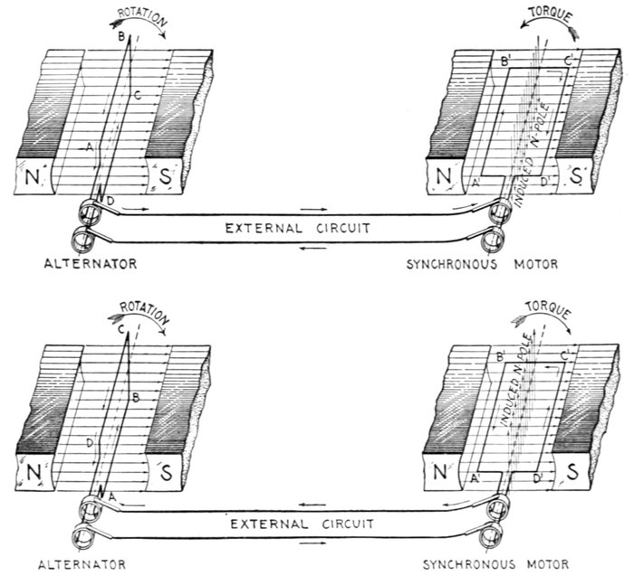
Figs. 1,585 to 1,588.—Synchronous motor principles: I. A single phase synchronous motor
is not self-starting. The figures show an elementary alternator and an elementary synchronous
motor, the construction of each being identical as shown. If the alternator
be started, during the first half of a revolution, beginning at the initial position ABCD,
fig. 1,585, current will flow in the direction indicated by the arrows, passing through the
external circuit and armature of the motor, fig. 1,586, inducing magnetic poles in the
latter as shown by the vertical arrows. These poles are attracted by unlike poles of the
field magnets, which tend to turn the motor armature in a counter-clockwise direction.
Now, before the torque thus set up has time to overcome the inertia of the motor armature
and cause it to rotate, the alternator armature has completed the half revolution, and
beginning the second half of the revolution, as in fig. 1,587, the current is reversed and
consequently the induced magnetic poles in the motor armature are reversed also. This
tends to rotate the armature in the reverse direction, as in fig. 1,588. These reversals
of current occur with such frequency that the force does not act long enough in either
direction to overcome the inertia of the armature; consequently it remains at rest, or to be
exact, it vibrates. Hence, a single phase synchronous motor must be started by some
external force and brought up to a speed that gives the same frequency as the alternator
before it will operate. A single phase synchronous motor, then, is not self-starting, which is
one of its disadvantages; the reason it will operate after being speeded up to synchronism
with the alternator and then connected in the circuit is explained in figs. 1,589 to 1,592.
[Pg 1269]
3. With respect to speed, as
a. Constant speed;
b. Variable speed.
4. With respect to structural features, as
a. Enclosed;
b. Semi-enclosed;
c. Open;
d. Pipe ventilated;
e. Back geared;
f. Skeleton frame;
g. Riveted frame;
h. Ventilated; etc.
Of the above divisions and sub-divisions some are self-defining
and need little or no explanation; the others, however, will be
considered in detail, with explanations of the principles of operation
and construction.
Synchronous Motors.—The term "synchronous" means
in unison, that is, in step. A so called synchronous motor, then,
as generally defined, is one which rotates in unison or in step with
the phase of the alternating current which operates it.
Strictly speaking, however, it should be noted that this condition of
operation is only approximately realized as will be later shown.
Any single or polyphase alternator will operate as a synchronous
motor when supplied with current at the same pressure
and frequency as it produces as a generator, the essential condition,
in the case of a single phase machine, being that it be
speeded up to so called synchronism before being put in the circuit.
In construction, synchronous motors are almost identical with
the corresponding alternator, and consist essentially of two
elements:
- 1. An armature,
- 2. A field.
[Pg 1270]
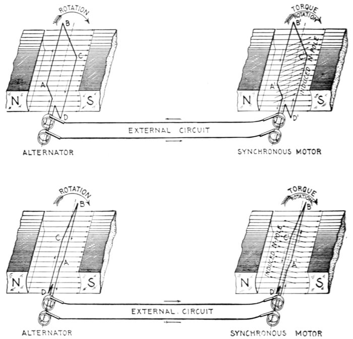
Figs. 1,589 to 1,592.—Synchronous motor principles: II. The condition necessary for synchronous
motor operation is that the motor be speeded up until it rotates in synchronism, that
is, in step with the alternator. This means that the motor must be run at the same frequency
as the alternator (not necessarily at the same speed). In the figures it is assumed that
the motor has been brought up to synchronism with the alternator and connected in
the circuit as shown. In figs. 1,589 and 1,590 the arrows indicate the direction of the current
for the armature position shown. The current flowing through the motor armature
induces magnetic poles which are attracted by the field poles, thus producing a torque in
the direction in which the armature is rotating. After the alternator coil passes the
vertical position, the current reverses as in fig. 1,591, and the current flows through the
motor armature in the opposite direction, thus reversing the induced poles as in fig. 1,592.
This brings like poles near each other, and since the motor coil has rotated beyond the vertical
position the repelling action of the like poles, and also the attraction of unlike poles,
produces a torque acting in the direction in which the motor is rotating. Hence, when the two
armatures move synchronously, the torque produced by the action of the induced poles
upon the field poles is always in the direction in which the motor is running, and accordingly,
tends to keep it in operation.
[Pg 1271]
either of which may revolve. The field is separately excited with
direct current.
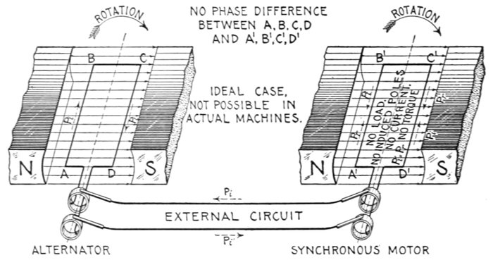
Figs. 1,593 and 1,594.—Synchronous motor principles: III. The current which flows through the
armature of a synchronous motor is that due to the effective pressure. Since the motor
rotates in a magnetic field, a pressure is induced in its armature in a direction opposite
to that induced in the armature of the alternator, and called the reverse pressure, as distinguished
from the pressure generated by the alternator called the impressed pressure.
At any instant, the pressure available to cause current to flow through the two armatures, called
the effective pressure, is equal to the difference between the pressure generated by the
alternator or impressed pressure and the reverse pressure induced in the motor. Now
if the motor be perfectly free to turn, that is, without load or friction, the reverse pressure
will equal the impressed pressure and no current will flow. This is the case of real synchronous
operation, that is, not only is the frequency of motor and alternator the same,
but the coils rotate without phase difference. In figs. 1,593 and 1,594, the impressed and
reverse pressures are represented by the dotted arrows Pi and Pr, respectively. Since in
this case these opposing pressures are equal, the resultant or effective pressure is zero;
hence, there is no current. In actual machines this condition is impossible, because even if
the motors have no external load, there is always more or less friction present; hence, in
operation there must be more or less current flowing through the motor armature to
induce magnetic poles so as to produce sufficient torque to carry the load. The action of
the motor in automatically adjusting the effective pressure to suit the load is explained in
figs. 1,595 and 1,596.
The principles upon which such motors operate may be explained
by considering the action of two elementary alternators
connected in circuit, as illustrated in the accompanying illustrations,
one alternator being used as a generator and the other as
a synchronous motor.
Suppose the motor, as in figs. 1,585 and 1,586, be at rest when[Pg 1272]
it is connected in circuit with the alternator. The alternating
current will flow through the motor armature and produce a
reaction upon the field tending to rotate the motor armature
first in one direction, then in another.
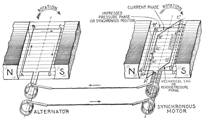
Figs. 1,595 and 1,596.—Synchronous motor principles: IV—A synchronous motor adjusts
itself to changes of load by changing the phase difference between current and pressure. If
there be no load and no friction, the motor when speeded up and connected in the circuit,
will run in true synchronism with the alternator, that is, at any instant, the coils
A B C D and A°B°C°D° will be in parallel planes. When this condition obtains, no
current will flow and no torque will be required (as explained in figs. 1,593 and 1,594).
If a load be put on the motor, the effect will be to cause A°B°C°D° to lag behind the
alternator coil to some position A"B"C"D" and current to flow. The reverse pressure
will lag behind the impressed pressure equally with the coil, and the current which has
now started will ordinarily take an intermediate phase so that it is behind the impressed
pressure but in advance of the reverse pressure. These phase relations may be represented
in the figure by the armature positions shown, viz.: 1, the synchronous position A°B°C°D°
representing the impressed pressure, 2, the intermediate position A'B'C'D', the current,
3, the actual position A"B"C"D" (corresponding to mechanical lag), the reverse pressure.
From the figure it will be seen that the current phase represented by A'B'C'D'
is in advance of the reverse pressure phase represented by A"B"C"D". Hence, by
armature reaction, the current leading the reverse pressure weakens the motor field and
reduces the reverse pressure, thus establishing equilibrium between current and load. As
the load is increased, the mechanical lag of the alternator coil becomes greater and likewise
the current lead with respect to the reverse pressure, which intensifies the armature
reaction and allows more current to flow. In this way equilibrium is maintained
for variations in load within the limits of zero and 90° mechanical lag. The effect of
armature reaction on motors is just the reverse to its effect on alternators, which results
in marked automatic adjustment between the machines especially when a single motor
is operated from an alternator of about the same size. In other words, the current
which weakens or strengthens the motor field, strengthens or weakens respectively the
alternator field as the load is varied.
[Pg 1273]
Because of the very rapid reversals in direction of the torque thus set up,
there is not sufficient time to overcome the inertia of the armature
before the current reverses and produces a torque in the opposite direction,
hence, the armature remains stationary or, strictly speaking, it vibrates.
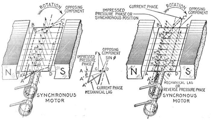
Figs. 1,597 and 1,598.—Synchronous motor principles: V. The effectiveness of armature reaction
in weakening the field is proportional to the sine of the angle by which the current lags
behind the impressed pressure. If a motor be without load or friction, its armature will
revolve synchronously (in parallel planes) with the alternator armature. In the figures
let ABCD represent an instantaneous position of the motor armature when this condition
obtains; it will then represent the phase relationship of impressed and reverse pressures
for the same condition of no load, no friction, operation. Now, if a light load be placed
on the motor for the same instantaneous position of alternator armature, the motor coil
will drop behind to some position as A", fig. 1,597 (part of the coil only being shown).
The reverse pressure will also lag an equal amount and its phase with respect to the impressed
pressure will be represented by A". The armature current will ordinarily take an intermediate
phase, represented by coil position A'B'C'D', inducing a field strength corresponding to
the 9 lines of force OF, O'F', etc. The current being in advance of the phase of the reverse
pressure A", the armature reaction weakens the field, thus reducing the reverse pressure and
allowing the proper current to flow to balance the load. The amount by which the field is
weakened may be determined by resolving the induced magnetic lines OF, O'F', O"F", etc.,
into components OG, GF, O'G', G'F', O"G", G"F", etc., respectively parallel and at right
angles to the lines of force of the main field. Of these components, the field is weakened
only by OG, O'G', O"G", etc. Since by construction, angle OFG = AOA', and calling OF
unity length, OG = sine of angle by which the current lags behind the impressed pressure.
The construction is shown better in the enlarged diagram. For a heavier load the armature
coil will drop back further to some position as A"', fig. 1,598, and the lag of the
current increase to some intermediate phase as A"B"C"D". By similar construction it
is seen that the component OG (fig. 1,597) has increased to OJ (fig. 1,598), this component
thus further weakening the main field, by an amount proportional to the sine of
the angle by which the current lags behind the impressed pressure. The increased current
which is now permitted to flow, causes the induced field to be strengthened (as indicated
by the dotted magnetic lines M, M', M", etc.), thus increasing the torque to balance
the additional load.
Now if the motor armature be first brought up to a speed corresponding
in frequency to that of the alternator before connecting the motor[Pg 1274]
in the circuit, the armature will continue revolving at the same frequency
as the alternator.
The armature continues revolving, because, at synchronous speed,
the field flux and armature current are always in the same relative position,
producing a torque which always pulls the armature around in the same
direction.
A polyphase synchronous motor is self starting, because, before the
current has died out in the coils of one phase, it is increasing in those of
the other phase or phases, so that there is always some turning effort
exerted on the armature.
The speed of a synchronous motor is that at which it would have to
run, if driven as an alternator, to deliver the number of cycles which is
given by the supply alternator.
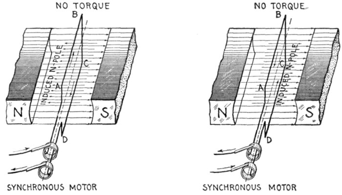
Figs. 1,599 and 1,600.—Synchronous motor principles: VI. A single phase synchronous motor
has "dead centers," just the same as a one cylinder steam engine. Two diagrams of the
motor are here shown illustrating the effect of the current in both directions. When the
plane of the coil is perpendicular to the field, the poles induced in the armature are parallel
to field for either direction of the current; that is to say, the field lines of force and the
induced lines of force acting in parallel or opposite directions, no turning effect is produced,
just as in analogy when an engine is on the dead center, the piston rod (field line of force)
and connecting rod (induced line of force) being in a straight line, the force exerted by
the steam on the piston produces no torque.
For instance a 12 pole alternator running at 600 revolutions per
minute will deliver current at a frequency of 60 cycles a second; an
8 pole synchronous motor supplied from that circuit will run at 900
revolutions per minute, which is the speed at which it would have to be
driven as an alternator to give 60 cycles a second—the frequency of
the 12 pole alternator.
[Pg 1275]
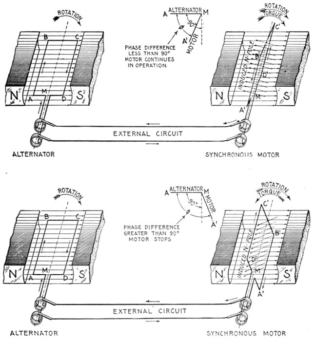
Figs. 1,601 to 1,604.—Synchronous motor principles VII. An essential condition for synchronous
motor operation is that the mechanical lag be less than 90°. Figs. 1,601 and 1,602
represent the conditions which prevail when the lag of the motor armature A'B'C'D' is
anything less than 90°. As shown, the lag is almost 90°. The direction of the current and
induced poles are indicated by the arrows. The inclination of the motor coil is such that
the repulsion of like poles produces a torque in the direction of rotation, thus tending
to keep motor in operation. Now, in figs. 1,603 and 1,604, for the same position of the alternator
coil ABCD, if the lag be greater than 90°, the inclination of the motor coil A'B'C'D' is
such that at this instant the repulsion of like poles produces a torque in a direction opposite
to that of the rotation, thus tending to stop the motor. In actual operation this quickly
brings the motor to rest, having the same effect as a strong brake in overcoming the
momentum of a revolving wheel.
[Pg 1276]
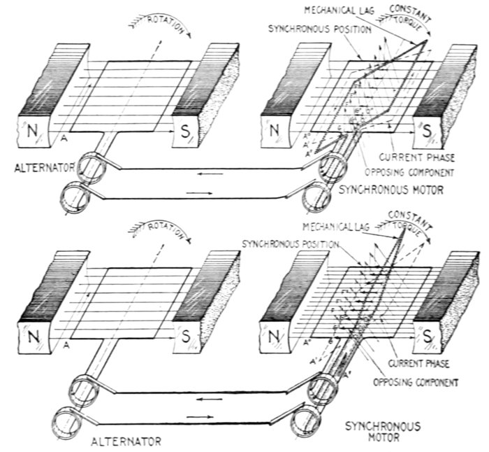
Figs. 1,605 to 1,608.—Synchronous motor principles: VIII. If the torque and current through
the motor armature be kept constant, strengthening the field will increase the mechanical lag,
and the lead of the current with respect to the reverse pressure. In the figures, let A be an
instantaneous position of the alternator coil, A°, synchronous position of motor coil,
A', position corresponding to current phase, A", actual position or mechanical lag of
motor coil behind alternator coil necessary to maintain equilibrium. In fig. 1,606, let A'
and A" represent respectively the relation of current phase and mechanical lag corresponding
to a certain load and field strength. For these conditions OG, O'G', O"G",
etc., will represent the components of the induced lines of force in opposition to the motor
field, that is, they indicate the intensity of the armature reaction at the instant depicted.
Now, assume the field strength to be doubled, as in fig. 1,608, the motor load and current
being maintained constant. Under these conditions, the armature reaction must be
doubled to maintain equilibrium; that is, the components OG, O'G', etc., fig. 1,608, must
be twice the length of OG, O'G', etc., fig. 1,605. Also since the current is maintained
constant, the induced magnetic lines OF, O'F' are of same length in both figures. Hence,
in fig. 1,608 the plane of these components is such that their extremities touch perpendiculars
from G, G', etc., giving the other components FG, F'G', etc. The plane A',
normal to OF, O'F', etc., gives the current phase. By construction, the phase difference
between A° and A' is such that sin A°OA' (fig. 1,608) = 2 × sin A°OA' (fig. 1,606). That
is, doubling the field strength causes an increase of current lag such that the sine of the
angle of this lag is doubled. Since the intensity of the armature reaction depends on the
lead of the current with respect to the reverse pressure, the mechanical lag of the coil must
be increased to some position as A" (fig. 1,608), such as will give an armature reaction of an
intensity indicated by the components OG, O'G', etc.
[Pg 1277]
The following simple formula gives the speed relations between
generators and motors connected to the same circuit and having different
numbers of poles.
in which
- s. Revolutions per minute of the motor;
- p. Number of poles of the motor;
- S. Revolutions per minute of the alternator;
- P. Number of poles of the alternator.
Question. If the field strength of a synchronous motor
be altered, what effect does this have on the speed, and
why?
Ans. The speed does not change (save for a momentary
variation to establish the phase relation corresponding to
equilibrium), because the motor has to run at the same frequency
as the alternator.
Ques. How does a synchronous motor adjust itself to
changes of load and field strength?
Ans. By changing the phase difference between the current
and pressure.
If, on connecting a synchronous motor to the mains, the excitation
be too weak, so that the voltage is lower than that of the supply, this
phase difference will appear resulting in wattless current, since the
missing magnetization has, as it were, to be supplied from an external
source. A phase difference also appears when the magnetization is too
strong.
Ques. State the disadvantages of synchronous motors.
Ans. A synchronous motor requires an auxiliary power for
starting, and will stop if, for any reason, the synchronism be
destroyed; collector rings and brushes are required. For some
purposes synchronous motors are not desirable, as for driving
shafts in small workshops having no other power available for
starting, and in cases where frequent starting, or a strong torque[Pg 1278]
at starting is necessary. A synchronous motor has a tendency
to hunt[1] and requires intelligent attention; also an exciting
current which must be supplied from an external source.
Ques. State the advantage of synchronous motors.
Ans. The synchronous motor is desirable for large powers
where starting under load is not necessary. Its power factor
may be controlled by varying the field strength. The power
factor can be made unity and, further, the current can be made
to lead the pressure.
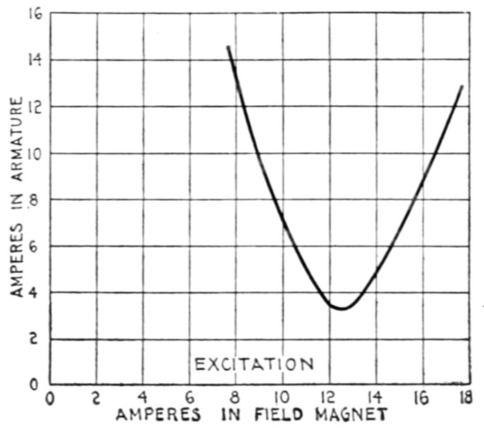
Fig. 1,609.—Diagram illustrating method of representing the performance of synchronous
motors. The V shaped curve is obtained by plotting the current taken by motor under
different degrees of excitation, the power developed by the motor remaining constant.
The current may be made to lag or lead while the load remains constant, by varying
the excitation. By varying the excitation, a certain value may be reached which will
give a minimum current in the armature; this is the condition of unity power factor.
If now the excitation be diminished the current will lag and increase in value to obtain
the same power; if the excitation be increased the current will lead and increase in value
to obtain the same power. The results plotted for several values of the excitation current
will give the V curve as shown. This is an actual curve obtained by Mordey on a 50 kw.
machine running unloaded as a motor. Other curves situated above this one may be
obtained for various loadings of the motor.
A synchronous motor is frequently connected in a circuit solely to
improve the power factor. In such cases it is often called a "condenser
motor" for the reason that its action is similar to that of a condenser.
[Pg 1279]
The design of synchronous motors proceeds on the same lines as
that of alternators, and the question of voltage regulation in the latter
becomes a question of power factor regulation in the former.
Ques. For what service are they especially suited?
Ans. For high pressure service.
High voltage current supplied to the armature does not pass through
a commutator or slip rings; the field current which passes through slip
rings being of low pressure does not give any trouble.
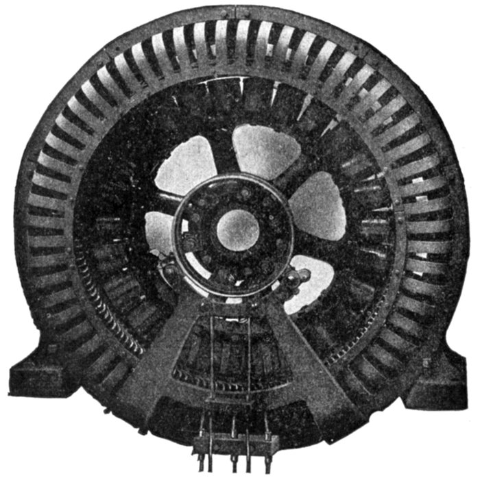
Fig. 1,610.—Westinghouse self-starting synchronous motor. Motors of this type are suitable
for constant speed service where starting conditions are moderate, such as driving
compressors, pumps, and large blowers. Synchronous motors can be made to operate
not only as motors but as synchronous condensers to improve the power factor of the
circuit. The field is provided with a combined starting and damper or amorlisseur winding
so proportioned that the necessary starting torque is developed by the minimum current
consistent with satisfactory synchronous running without hunting. The armature slots are
open and the coils form wound, impregnated, and interchangeable. Malleable iron finger
plates at each end of the core support the teeth. Ventilating finger plates assembled with
the laminations form air ducts. The frames are of cast iron, box section with openings for
ventilation; shoes and slide rails permit adjustment of position. The brush holders are of
the standard sliding shunt type. Two or more brushes are provided for each ring.
[Pg 1280]
Ques. How do synchronous and induction motors
compare as to efficiency?
Ans. Synchronous motors are usually the more efficient.
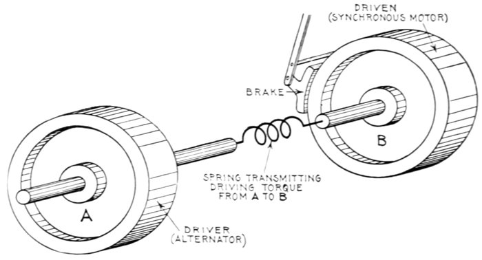
Fig. 1,611.—Mechanical analogy illustrating "hunting." The figure represents two flywheels
connected by a spring susceptible to torsion in either direction of rotation. If the wheels
A and B be rotating at the same speed and a brake be applied, say to B, its speed will
diminish and the spring will coil up, and if fairly flexible, more than the necessary amount
to balance the load imposed by the brake; because when the position of proper torque is
reached, B is still rotating slightly slower than A, and an additional torque is required to
overcome the inertia of B and bring its speed up to synchronism with A. Now before the
spring stops coiling up the wheels must be rotating at the same speed. When this occurs
the spring has reached a position of too great torque, and therefore exerting more turning
force on B than is necessary to drive it against the brake. Accordingly B is accelerated
and the spring uncoils. The velocity of B thus oscillates above and below that of A when
a load is put on and taken off. Owing to friction, the oscillations gradually die out and
the second wheel takes up a steady speed. A similar action takes place in a synchronous
motor when the load is varied.
Hunting of Synchronous Motors.—Since a synchronous
motor runs practically in step with the alternator supplying it
with current when they both have the same number of poles,
or some multiple of the ratio of the number of poles on each
machine, it will take an increasing current from the line as its
speed drops behind the alternator, but will supply current to the
line as a generator if for any reason the speed of the alternator[Pg 1281]
should drop behind that of the motor, or the current wave lag
behind, which produces the same effect, and due to additional
self-induction or inductance produced by starting up or overloading
some other motor or rotary converter in the circuit.
When the motor is first taking current, then giving current
back to the line, and this action is continued periodically, the
motor is said to be hunting.
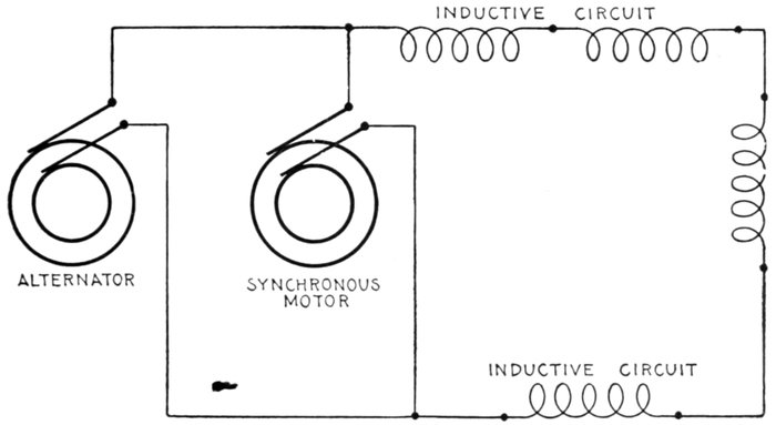
Fig. 1,612.—Diagram illustrating the use of a synchronous motor as a condenser. If a synchronous
motor be sufficiently excited the current will lead. Hence, if it be connected
across an inductive circuit as in the figure and the field be over excited it will compensate
for the lagging current in the main, thus increasing the power factor. If the motor
be sufficiently over excited the power factor may be made unity, the minimum current
being thus obtained that will suffice to transmit the power in the main circuit. A synchronous
motor used in this way is called a rotary condenser or synchronous compensator.
This is especially useful on long lines containing transformers and induction motors.
Ques. What term is applied to describe the behavior
of the current when hunting occurs?
Ans. The term surging is given to describe the current
fluctuations produced by hunting.
The mechanical analogy of hunting illustrated in fig. 1,611 will help
to an understanding of this phenomenon. In alternating current circuits
a precisely similar action takes place between the alternators and synchronous
motors, or even between the alternators themselves.
[Pg 1282]
CHARACTERISTICS OF SYNCHRONOUS MOTORS
Starting.—The motor must be brought up to synchronous speed
without load, a starting compensator being used. If provided with
a self-starting device, the latter must be cut out of circuit at the proper
time. The starting torque of motor with self-starting device is very small.
Running.—The motor runs at synchronous speed. The maximum
torque is several times full load torque and occurs at synchronous speed.
Stopping.—If the motor receive a sudden overload sufficient to momentarily
reduce its speed, it will stop; this may be brought about by
momentary interruption of the current, sufficient to cause a loss of
synchronism.
Effect upon Circuit.—In case of short circuit in the line the motor
acts as a generator and thus increases the intensity of the short circuit.
The motor impresses its own wave form upon the circuit. Over
excitation will give to the circuit the effect of capacity, and under
excitation, that of inductance.
Power Factor.—This depends upon the field current, wave form
and hunting. The power factor may be controlled by varying the
field excitation.
Necessary Auxiliary Apparatus.—Power for starting, or if self-starting,
means of reducing the voltage while starting; also, field exciter,
rheostat, friction clutch, main switch and exciter switch, instruments
for indicating when the field current is properly adjusted.
Adaptation.—If induction motors be connected to the same line
with a synchronous motor that has a steady load, then the field of the synchronous
motor can be over excited to produce a leading current, which
will counteract the effect of the lagging currents induced by the induction
motors. Owing to the weak starting torque, skilled attendance required,
and the liability of the motor to stop under abnormal working
conditions, the synchronous motor is not adapted to general power distribution,
but rather to large units which operate under a steady load and
do not require frequent starting and stopping.
[Pg 1283]
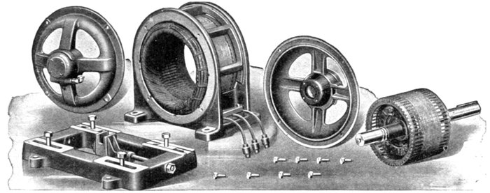
Figs. 1,613 to 1,625.—Disassembled view of Western Electric three phase squirrel cage skeleton frame induction motor.
Induction (Asynchronous)
Motors.—
An induction motor consists
essentially of an
armature and a field magnet,
there being, in the
simplest and most usual
types, no electrical connection
between these two
parts.[2]
According to the kind
of current that an induction
motor is designed
to operate on, it may be
classified as:
- 1. Single phase;
- 2. Polyphase.
The operation of an
induction motor depends
on the production
of a magnetic field by
passing an alternating
current through field
magnets.
[Pg 1284]
The character of this field is either
- 1. Oscillating[3], or
- 2. Rotating,
according as single phase or polyphase current is used.
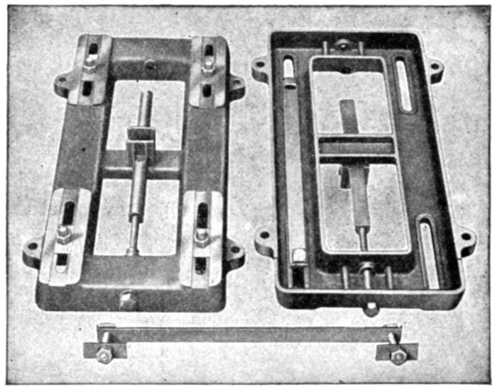
Figs. 1,626 to 1,628.—General Electric base construction for polyphase induction motors.
The base is made of cast iron. Adjusting gear is provided to slide the motor along the
base as shown in the illustrations, the movement being from 6 to 12 inches according to
size. With this design of base, motors are securely held in position under all conditions and
may be run with an upward pull on the belt. Close fitting guides moving in an accurately
machined slot on the base preserve a correct alignment of the motor when adjustment of
the latter is required. The same base can be used whether the motor be supported from
the wall or ceiling or located on the floor. A single adjusting screw is placed under the
center line of the motor frame, which produces an even and balanced draw in either
direction on all parts of the motor when the belt tension is altered. This screw can be
located at either end of the base. The base can be omitted when the motor is direct connected
or when provision for belt adjustment is not required.
Ques. Describe briefly the operation of a single phase
motor.
Ans. A single phase current being supplied to the field
magnets, an oscillating field is set up. A single phase motor is[Pg 1285]
not self-starting; but when the armature has been set in motion
by external means, the reaction between the magnetic field and the
induced currents in the armature being no longer zero, a torque
is produced tending to turn the armature.
The current flowing through the armature produces an alternating
polarity such that the attraction between the unlike armature and field
poles is always in one direction, thus producing the torque.
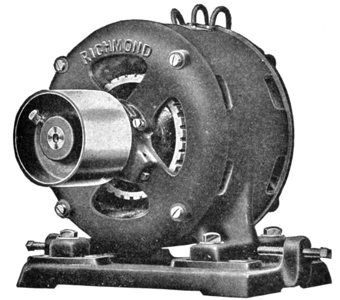
Fig. 1,629.—Richmond three phase induction motor on base fitted with screw adjusting gear
for shifting the position of the motor on the base to take up slack of belt.
Ques. Why is a single phase induction motor not self-starting?
Ans. When the armature is at the rest, the currents induced
therein are at a maximum in a plane at right angles to the
magnetic field, hence there is no initial torque to start the motor.
[Pg 1286]
Ques. What
provision is
made for
starting single
phase induction
motors?
Ans. Apparatus
is supplied
for "splitting
the phase"
(later described
in detail) of the
single phase current
furnished,
converting it
temporarily into
a two phase current,
so as to
obtain a rotating
field which is
maintained till
the motor is
brought up to
speed. The
phase splitting
device is then
cut out and the
motor operated
with the oscillating
field produced
by the
single phase
current.
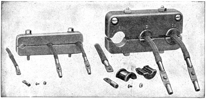
Figs. 1,630 to 1,641.—Terminals for General Electric polyphase induction motors. In order to prevent any mechanical
strain on the leads being transmitted to the motor windings, the terminal cables are clamped in insulated
bushings with a connector for each cable.
[Pg 1287]
Ques. Describe briefly the operation of a polyphase
induction motor.
Ans. Its operation is due to the production of a rotating
magnetic field by the polyphase current furnished. This field
"rotating" in space about the axis of the armature induces
currents in the latter. The reaction between these currents and
the rotating field creates a torque which tends to turn the armature,
whether the latter be at rest or in motion.
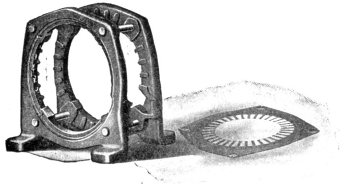
Figs. 1642 and 1643.—Western Electric end flange rivets and punchings of riveted frame induction
motor. The riveted frame is constructed of two cast iron flanges between which the
stator laminations of sheet steel are securely clamped and riveted under hydraulic pressure.
This construction exposes the laminations directly to the air and improves the radiation,
thus insuring high overload capacity and low operating temperatures. The field slots are
overhung or partially closed, affording mechanical protection to the coils.
Ques. Why are induction motors called "asynchronous"?
Ans. Because the armature does not turn in synchronism
with the rotating field, or, in the case of a single phase induction
motor, with the oscillating field (considering the latter in the
light of a rotating field).
Ques. How does the speed vary?
Ans. It is slower (more or less according to load) than the
"field speed," that is, than "synchronism" or the "synchronous
speed."
[Pg 1288]
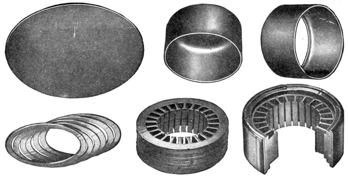
Figs. 1,644 to 1,649.—Construction of General Electric drawn shell fractional horse power motors. The distinguishing feature
of drawn shell motors is the field construction which consists of a steel shell or cylinder supporting and clamping together the
stator or field punchings. This method avoids the cast frame work outside the active magnetic material. A disc is first punched or
"blanked" out of soft steel, fig. 1,644, this disc being faced into the shape, fig. 1,645, with one end closed. The other end of the
shell is then cut out, leaving the small flange as in fig. 1,646. It is now ready to receive the core punchings. In the next operation
a suitable number of spacing rings, fig. 1,647, are forced into the shell and seated against the retaining lip, which may
be seen in fig. 1,646. The field punchings or laminæ, fig. 1,648, are now assembled, after which a second and equal set of spacing
rings are put into place to center the active field iron. The open edge of the shell is then rolled over the punchings under
heavy pressure, thus preparing the field structure for the machining and fitting of the end heads and base. Fig. 1,649 shows
a section of the completely assembled field structure, the parts being cut away to indicate the relation between the field
punchings, spacing rings and shell. After the spacing rings at both frame ends have been turned true and grooved, the
bearing heads, fig. 1,649, are ready for fastening in place by four fillister headed screws. A complete wound field is shown in
fig. 1,858, with flat base casting attached.
[Pg 1289]
Ques. What is the difference of speed called?
Ans. The slip.
This is a vital factor in the operation of an induction motor, since
there must be slip in order that the armature inductors shall cut magnetic
lines to induce (hence the name "induction" motor) currents therein
so as to create a driving torque.
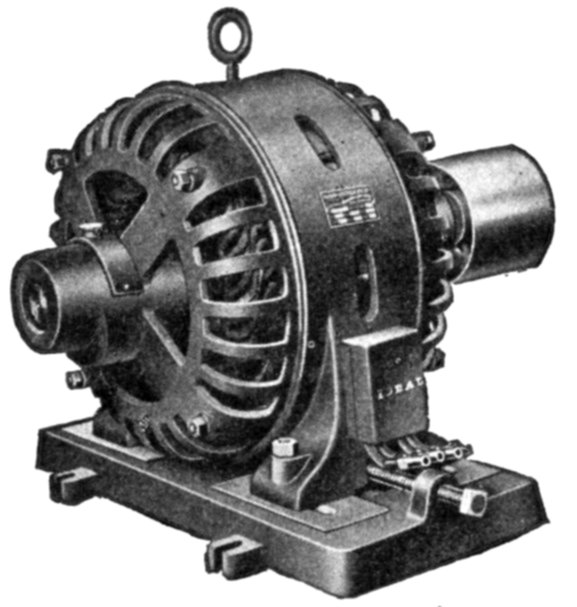
Fig. 1,650.—Ideal fifteen horse power two phase induction motor. The armature core is
supported by a cast iron frame carried on a base, with sliding ways and screw adjustment
for tightening the belt. The armature core is provided with ventilating apertures,
with metal spacers between each tooth. The revolving field is a steel casting with radially
projecting poles, to which the pole shoes are bolted. The overhanging pole tips
retain the field coils. All coils of the smaller sizes are wound with insulated copper wire
of square section, and of the larger sizes, with flat copper, wound on edge, each turn being
insulated by sheet insulation. Motors of this type are adapted for use in small power
plants and isolated plants. The relatively high speed for which they are designed, reduces
considerably the weight and overall dimensions, and likewise the cost. The exciter
is belt driven. The normal kw. capacity of the exciter usually exceeds the kw. required
for the excitation under normal load conditions to permit of station lighting. All exciters
are built as compound wound dynamos, capable of delivering the exciter current up to
125 volts, which is sufficient margin in the field to control the alternating current line
voltage on circuits of unusually low power factor.
Ques. What is the extent of the slip?
Ans. It varies from about 2 to 5 per cent. of synchronous
speed depending upon the size.
Ques. Why are induction motors sometimes called
constant speed motors?
Ans. They are erroneously and ill advisedly, yet conveniently
so called by builders to distinguish them from induction motors[Pg 1290]
fitted with special devices to obtain widely varying speeds, and
which are known as variable speed induction motors.
The term adjustable would be better.
Motor, Constant Speed.—A motor in which the speed is either constant or does not
materially vary; such as synchronous motors, induction motors with small slip, and ordinary
direct current shunt motors.—Paragraph 46 of 1907 Standardization Rules of the A.I.E.E.
Motor, Variable Speed.—A motor in which provision is made for varying the speed as
desired. The A.I.E.E. has unfortunately introduced the term varying speed motor, to designate
"motors in which the speed varies with the load, decreasing when the load increases, such as
series motors." The term is objectionable, since by the expression variable speed motor a much
more general meaning is intended.
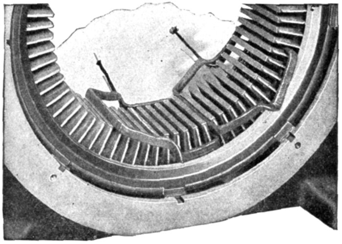
Fig. 1,651.—Western Electric core construction and method of winding field of skeleton
frame induction motor. The coils are wound on forms to give them exact shape and
dimensions required. They are pressed into hot moulds to remove any irregularities and
then the coils are impregnated with hot cement, to bind the layers together in their permanent
shape. The portion of the coil which fits into the slot is wrapped with varnished
cloth and a layer of dry tape is wound over the entire coil. The coils are then impregnated
with an insulating compound and baked, the process being repeated six times. Coils for
1,100 and 2,200 volt motors have an extra covering of insulation and double the amount
of impregnating and baking. The coils may be furnished with special insulation and
treatment for exceptionally severe service conditions, such as exposure to excessive
moisture, extreme heat, acid or alkaline fumes, etc. The coils are accessible and for the
final finish are sprayed with black varnish.
Ques. Why do some writers call the field magnets and
armature the primary and secondary, respectively?
Ans. Because, in one sense, the induction motor is a species
of transformer, that is, it acts in many respects like a transformer,
the primary winding of which is on the field and the
secondary winding on the armature.
[Pg 1291]
In the motor the function of the secondary circuit is to furnish energy
to produce a torque, instead of producing light and heat as in the case
of the transformer. Such comparisons are ill advised when made for
the purpose of supplying names for motor parts. There can be no
confusion by employing the simple terms armature and field magnets,
remembering that the latter is that part that produces the oscillating or
rotating field (according as the motor is single or polyphase), and the
former, that part in which currents are induced.
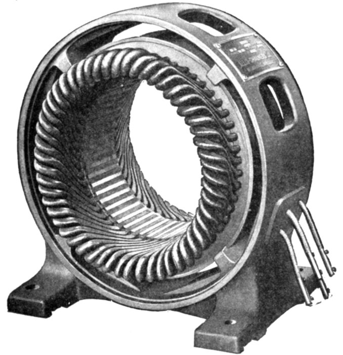
Fig. 1,652.—Armature of Allis-Chalmers squirrel cage induction motor. The frame casting
is of the box type and has large cored openings for ventilation. Lugs are cast on the
interior surface of the frame to support the core, leaving a large air space between.
Ques. Why are polyphase induction motors usually
presented in text books before single phase motors?
Ans. Because the latter must start with a rotating field and
come up to speed before the oscillating field can be employed.
A knowledge then of the production of a rotating field is necessary
to understand the action of the single phase motor at starting.
[Pg 1292]
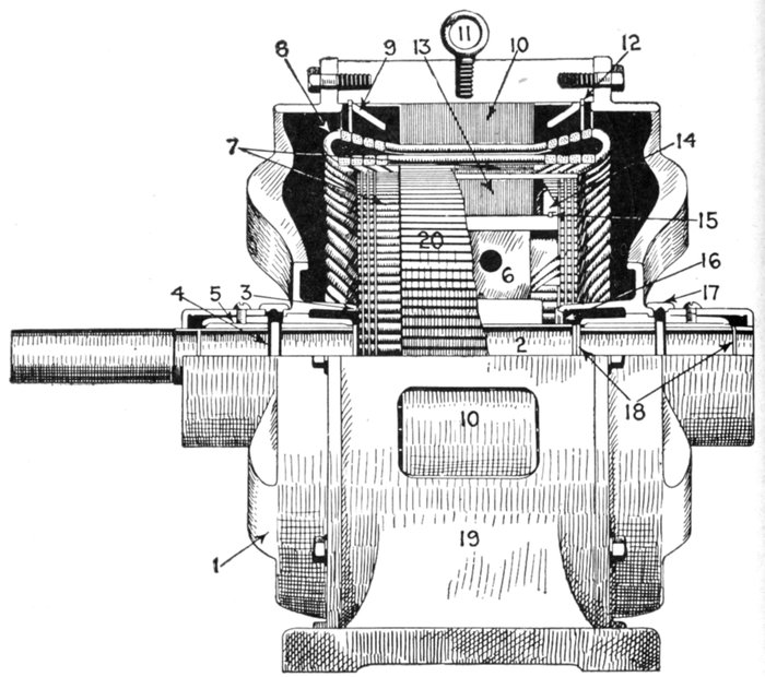
Fig. 1,653.—Sectional view showing parts of Reliance polyphase induction motor. A special
feature of the squirrel cage armature construction is the multiplicity of short circuiting
rings. The holes in the rings are bored slightly smaller than the diameter of the copper
rods, and the force fit gives good contact. The rings having been forced in place are dip
soldered in an alloy of tin of high melting point. The motor parts are: 1, end yoke;
2, shaft; 3, armature short circuiting rings; 4, oil ring; 5, self-aligning bearing bushing;
6, spider; 7, armature bars; 8, field coils; 9, field lamination end plate; 10, field laminations;
11, eye bolt; 12, stator locking key; 13, armature laminations; 14, armature lamination
end plate; 15, armature locking key; 16, dust cap; 17, oil well cover; 18, oil throws;
19, field frame; 20, squirrel cage armature.
[Pg 1293]
Polyphase Induction Motors.—As many central stations
put out only alternating current circuits, it has become necessary
for motor builders to perfect types of alternating current
motor suitable for all classes of industrial drive and which are
adapted for use on these commercial circuits. Three phase
induction motors are slightly more efficient at all loads than two
phase motors of corresponding size, due to the superior distribution
of the field windings. The power factor is higher, especially
at light loads, and the starting torque with full load current is
also greater. Furthermore, for given requirements of load and
voltage, the amount of copper required in the distributing system
is less; consequently, wherever service conditions will permit,
three phase motors are preferable to two phase.
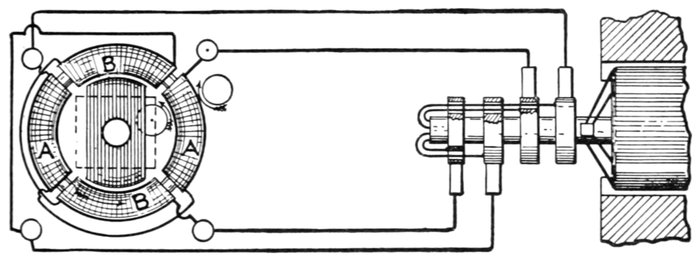
Fig. 1,654.—Tesla's rotating magnetic field. The figure is from one of Tesla's papers as given in
The Electrician, illustrating how a rotating magnetic field may be produced with stationary
magnets and polyphase currents. The illustration shows a laminated iron ring overwound
with four separate coils, AA, and BB, each occupying about 90° of the periphery. The
opposite pairs of coils AA and BB respectively are connected in series and joined to the
leads from a two phase alternator, the pair of coils AA being on one circuit and the coils
BB on the other. The resultant flux may be obtained by combining the two fluxes due to
coils AA and BB, taking account of the phase difference of the two phase current, as in
fig. 1,655.
The construction of an induction motor is very simple, and
since there are no sliding contacts as with commutator motors,
there can be no sparks during operation—a feature which adapts
the motor for use in places where fire hazards are prominent.
The motor consists, as already mentioned, simply of two parts:
an armature and field magnets, without any electrical connection
between these parts. Its operation depends upon:
[Pg 1294]
- 1. The production of a rotating field;
- 2. Induction of current in the armature;
- 3. Reaction between the revolving field and the induced currents.
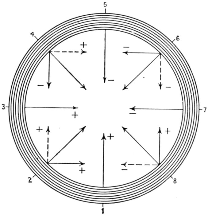
Fig. 1,655.—Method of obtaining resultant flux of Tesla's rotating magnetic field. The
eight small diagrams here seen show the two components and resultant for eight
equivalent successive instants of time during one cycle. At 1, the vertical flux is at
+ maximum and the horizontal is zero. At 2, the vertical flux is still + but decreasing,
and the horizontal is + and increasing, the resultant is the thick line sloping at 45° upwards
to the right. At 3, the vertical flux is zero, and the horizontal is at its + maximum,
and similarly for the other diagrams. Thus at 8, the vertical flux is + and increasing,
while the horizontal is-and decreasing, the resultant is the thick line sloping at 45°
upwards to the left. At points 2, 4, 6, and 8 the increasing fluxes are denoted by full and
the decreasing by dotted lines. The laminated iron of the ring is indicated by the circles,
and the result is that at the instants chosen the flux across the plane of the ring is directed
inwards from the points 1, 2, 3, 4, etc., on the inner periphery of the iron. There will,
therefore, appear successively at these points effective north poles, the corresponding south
poles being simultaneously developed at the points diametrically opposite. These poles
travel continuously from one position to the next, and thus the magnetic flux across the
plane of the ring swings round and round, completing a revolution without change of
intensity during the cycle time of the current.
Production of a Rotating Field.—It should at once be
understood that the term "rotating field" does not signify that
part of the apparatus revolves, the expression merely refers to[Pg 1295]
the magnetic lines of force set up by the field magnets without
regard to whether the latter be the stationary or rotating member.
A rotating field then may be defined as the resultant magnetic
field produced by a system of coils symmetrically placed and supplied
with polyphase currents.
A rotating magnetic field can, of course, be produced by spinning a
horse shoe magnet around its longitudinal axis, but with polyphase currents,
as will be later shown, the rotation of the field can be produced
Without any movement of the mechanical parts of the electro magnets.
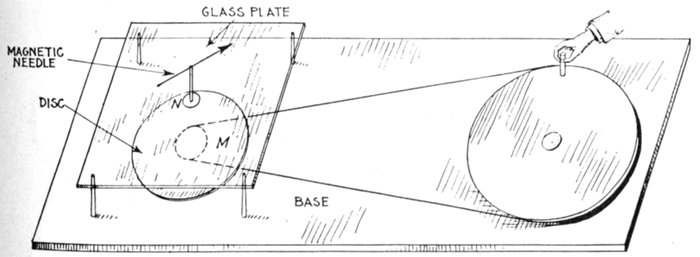
Fig. 1,656.—Arago's rotations. The apparatus necessary to make the experiment consists of
a copper disc M, arranged to rotate around a vertical axis and operated by belt drive, as
shown. By turning the large pulley by hand, the disc M may be rotated with great rapidity.
Above the disc is a glass plate on which is a small pivot supporting a magnetic needle N.
If the disc now be rotated with a slow and uniform velocity, the needle is deflected in the
direction of the motion, and stops at an angle of from 20° to 30° with the direction of the
magnetic meridian, according to the velocity of the rotation of the disc. If the velocity
increase, the needle is ultimately deflected more than 90° and then continues to follow the
motion of the disc.
The original rotating magnetic field dates back to 1823, when
Francois Jean Arago, an assistant in Davy's laboratory, discovered
that if a magnet be rotated before a metal disc, the
latter had a tendency to follow the motion of the magnet, as
shown in fig. 290, page 270 and also in fig. 1,656. This experiment
led up to the discovery which was made by Arago in 1824,
when he observed that the number of oscillations which a magnetized[Pg 1296]
needle makes in a given time, under the influence of the earth's
magnetism, is very much lessened by the proximity of certain
metallic masses, and especially of copper, which, may reduce the
number in a given time from 300 to 4.
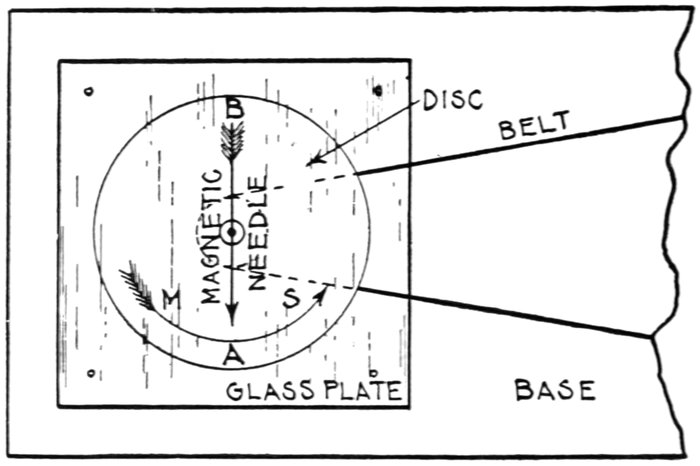
Fig. 1,657.—Explanation of Arago's rotations. Part of fig. 1,656 is here reproduced in plan.
Faraday was the first to give an explanation of the phenomena of magnetism by rotation
in attributing it to the induction of currents which by their electro-dynamic action, oppose
the motion producing them; the action is mechanically analogous to friction. In the
figure, let AB be a needle oscillating over a copper disc, and suppose that in one of its
oscillations it goes in the direction of the arrow from M to S. In approaching the point S,
for instance, it develops there a current in the opposite direction, and which therefore
repels it; in moving away from M it produces currents which are of the same kind, and
which therefore attract, and both these actions concur in bringing it to rest. Again,
suppose the metallic mass turn from M towards S, and that the magnet be fixed; the
magnet will repel by induction points such as M which are approaching A, and will attract
S which is moving away; hence the motion of the metal stops, as in Faraday's experiment.
If in Arago's experiment the disc be moving from M to S, M approaches A and repels it,
while S, moving away, attracts it; hence the needle moves in the same direction as the disc.
If this explanation be true, all circumstances which favor induction will increase the
dynamic action; and those which diminish the former will also lessen the latter.
The explanation of Arago's rotations is that the magnetic
field cutting the disc produces eddy currents therein and the
reaction between the latter and the field causes the disc to follow the
rotations of the field.
[Pg 1297]
The induction motor is a logical development of the experiment
of Arago, which so interested Faraday while an assistant in
Davy's laboratory and which led him to the discovery of the laws
of electromagnetic induction, which are given in Chapter X.
[4]In 1885, Professor Ferraris, of Turin discovered that a
rotating field could be produced from stationary coils by means of
polyphase currents.

Fig. 1,658.—Experiment made by Faraday being the reverse of Arago's first observation.
Faraday assumed that since the presence of a metal at rest stops the oscillations of a
magnetic needle, the neighborhood of a magnet at rest ought to stop the motion of a
rotating mass of metal. He suspended a cube of copper by a twisted thread, which was
placed between the poles of a powerful electromagnet. When the thread was left to itself,
it began to spin round with great velocity, but stopped the moment a powerful current was
passed through the electromagnet.
[5]This discovery was commercially applied a few years later by
Tesla, Brown, and Dobrowolsky.
[Pg 1298]
The principles of polyphase motors can be best understood by
means of elementary diagrams illustrating the action of polyphase
currents in producing a rotating magnetic field, as explained
in the paragraphs following.
Production of a Rotating Magnetic Field by Two Phase
Currents.—Fig. 1,659 represents an iron ring wound with coils
of insulated wire, which are supplied with a two phase current
at the four points A, B, C, D, the points A and B, and C and D,
being electrically connected.

Fig. 1,659.—Production of a rotating magnetic field by two phase currents. The figure represents
an iron ring, wound with coils of insulated wire, and supplied with two phase currents
at the four points A, B, C, and D. The action of the two phase current on the ring in
producing a rotating magnetic field is explained in the accompanying text.
According to the principles of electromagnetic induction, if
only one current a entered the ring at A, and the direction of
the winding be suitable, a negative pole (-) will be produced at
A and a positive pole (+) at B, so that a magnetic needle
pivoted in the center of the ring would tend to point vertically[Pg 1299]
upward towards A. Now suppose that at this instant, corresponding
to the beginning of an alternating current cycle, a
second current b, differing in phase from the first by 90 degrees,
is allowed to enter the ring at C. As shown in fig. 1,659, when the
pressure of the current a is at its maximum, that of the current
b is at its minimum; therefore, even a two phase current, at the
beginning of the cycle, the needle will point toward A.
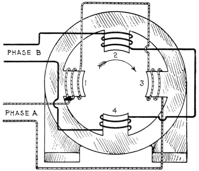
Fig. 1,660.—Production of rotating magnetic field in a two pole two phase motor. The poles
are numbered from 1 to 4 in a clockwise direction. Phase A winding is around poles 1
and 3, and phase B winding, around poles 2 and 4. In each case the poles are wound
alternately, that is, if 1 be wound clockwise, 3 will be wound counter clockwise, thus producing
unlike polarity in opposite poles. Now during one cycle of the two phase current,
the following changes take place, starting with pole 1 of N polarity and 3, of S polarity:
|
One Cycle |
| Degrees |
0° to 90° |
90° to 180° |
180° to 270° |
270° to 360° |
| Polarity |
1N - 3S |
2N - 4S |
3N - 1S |
4N - 2S |
[Pg 1300]
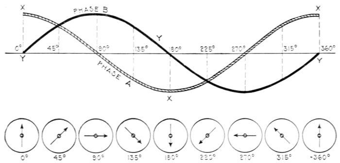
Fig. 1,661.—Diagram showing resultant poles due to two phase current.
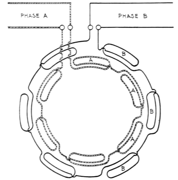
Fig. 1,662.—Diagram of two phase, six pole field winding. There are six coils in each phase,
as shown. The coils of each phase are connected in series, adjacent coils being joined
in opposite senses, thus, for each phase, first one coil is wound clockwise, and the
next counter clockwise.
[Pg 1301]
As the cycle continues, however, the strength of a will diminish
and that of b increase, thus shifting the induced pole toward C,
until b attains its maximum and a falls to its minimum at 90°
or the end of the first quarter of the cycle, when the needle will
point toward C. At 90°, the phase a current reverses in direction
and produces a negative pole at B, and as its strength increases
from 90° to the 180° point of the cycle, and that of phase b
diminishes, the resultant negative pole is shifted past C toward
B, until a attains its maximum and b falls to its minimum at
180°, and the needle points in the direction of B.

Fig. 1,663.—Diagram of two phase, eight pole field winding. The winding is divided into
16 groups (equal to the product of the number of poles multiplied by the number of phases).
Each group such as at A comprises a number of coils in series, each coil being located in a
separate pair of slots, the end of one being connected to the beginning of the next.
When the currents are in the same direction, the currents circulate in the same direction
in two adjacent groups, a pole then with this arrangement being formed by two
groups, both phases contributing to the formation of the pole. After ½ cycle when the
current in each phase reverses, the pole advances the angular distance, covered by two
groups; hence the field completes one revolution in eight alternations of current.
[Pg 1302]
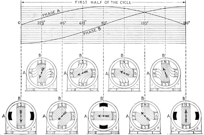
Figs. 1,664 to 1,683.—Sine curves of two phase current and diagrams showing the physical conception of a two phase rotating
magnetic field. The alternating magnetizing current is assumed to be of such strength that, at its maximum strength, the field
produced may be represented by 10 lines of force as indicated by the parallel lines. At the beginning of the rotation, fig. 1,664,
phase A magnetization, according to sine curve is zero, indicated by the solid black poles, while phase B is of strength 10 with
[Pg 1303]
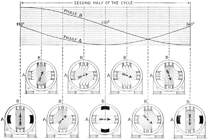
current in the direction to produce a south pole at B. Similarly, in fig. 1,665, the strength of A is 4 lines, and of B, 9 lines, the
resultant magnetization having rotated 22½°. The direction of the resultant magnetization is indicated by the arrow in each
figure. It should be noted in fig. 1,669, that the polarity of B is reversed, the current curve now being above the zero line. By
following the arrow through the successive positions the rotation of the resultant magnetization is clearly seen.
[Pg 1304]
At the 180° point of the cycle, b reverses in direction and produces
a negative pole at D, and as the fluctuation of the pressure
of the two currents during the second half of the cycle, from
180° to 360°, bear the same relation to each other as during the
first half, the resultant poles of the rotating magnetic field thus
produced carry the needle around in continuous rotation so
long as the two phase current traverses the windings of the ring.
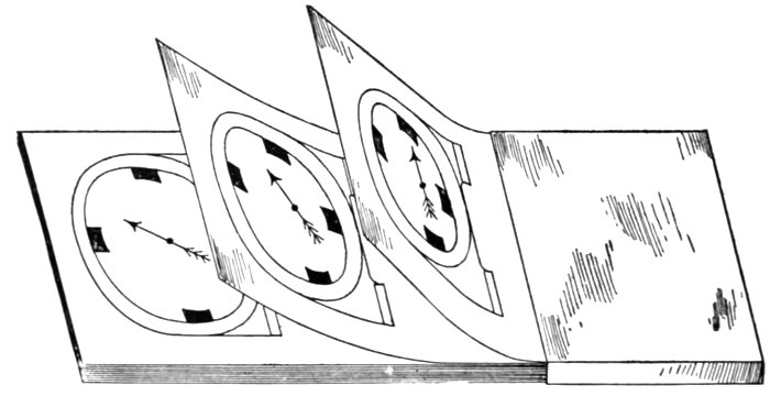
Fig. 1,684.—Moving picture method of showing motion of a rotary magnetic field. A number
of sheets of paper are prepared, each containing a drawing of the motor frame and a
magnetic needle in successively advancing angular positions, indicating resultant directions
of the magnetism. The sheets are bound together so that the axis of the needle on each
sheet coincides. When passing the sheets in one way the revolving field will be seen to
rotate in one direction, while, when moving the sheets backward, the rotation of the
magnetic field is in the opposite direction, showing that the reversal of the order of the
coils has the effect of reversing the rotation of the magnetic field.
Production of Rotating Magnetic Field by Three Phase
Current.—A rotating magnetic field is produced by the action
of a three phase current in a manner quite similar to the action
of a two phase current. Fig. 1,685 shows a ring suitably wound
and supplied with a three phase current at three points A, B, C,
120° of a cycle apart.
[Pg 1305]
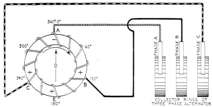
Fig. 1,685.—Production of a rotating magnetic field by three phase current. A ring wound as
shown is tapped at points A, B, and C, 120° apart, and connected with leads to a three
phase alternator. As described on page 1,304, a rotating magnetic field is produced
in a manner similar to the two phase method.
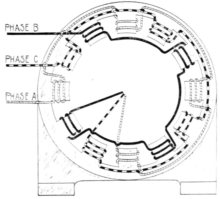
Fig. 1,686.—Diagram of three phase, four pole Y connected field winding.
[Pg 1306]
At the instant when the current a, flowing in at A, is at its maximum,
two currents b and c, each one-half the value of a, will flow out B and C,
thus producing a negative pole at A and a positive pole at B and at C.
The resultant of the latter will be a positive pole at E, and consequently,
the magnetic needle will point towards A.

Fig. 1,687.—Production of a rotating magnetic field in a two pole three phase motor. In
order to obtain a uniformly rotating magnetic field, it is necessary to arrange the phase
windings in the direction of rotation, in the sequence ACB, not ABC as indicated on the
magnets. Thus poles 1 and 4 are connected in series to phase A, 2 and 5 in series to phase
C, and 3 and 6 in series to phase B. The different phase windings are differently lined,
and it should be noted that they have a common return wire, though this is not absolutely
necessary. Since the phases of the three currents differ from each other by one-third
of a period or cycle, each of the phase windings will therefore set up a field between
its poles, which at any instant will differ, both in direction and magnitude, from the fields
set up by the other phase windings. Hence, the three phase windings acting together will
produce a resultant field, and if plotted out, the directions of this field for various fractions
of the period is such that in one complete period the resultant field will make one complete
round of the poles in a clockwise direction, as indicated by the curved arrow. The positions
of the resultant field during one complete period may be tabulated as follows:
|
One Cycle |
|
0° to 60° |
60° to 120° |
120° to 180° |
180° to 240° |
240° to 300° |
300° to 360° |
| Polarity |
1N - 4S |
2N - 5S |
3N - 6S |
4N - 1S |
5N - 2S |
6N - 3S |
[Pg 1307]
As the cycle advances, however, the mutual relations of the fluctuations
of the pressures of the three currents, and the time of their
reversals of direction will be such, that when a maximum current is
flowing at any one of the points A, B, and C, two currents each of one-half
the value of the entering current will flow out of the other two
points, and when two currents are entering at any two points, a current
of maximum value will flow out of the other point. This action will
produce one complete rotation of the magnetic field during each cycle
of the current.
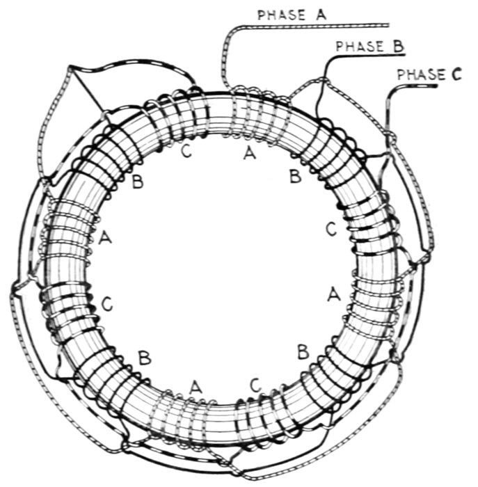
Fig. 1,688.—Production of three phase rotating magnetic field with winding on laminated
iron ring. The winding is divided into twelve sections, which are connected in three groups,
A, B, and C, of four sections each, the sections in each group being evenly placed round
the ring with the sections of the two other groups between them. One end of each group is
to be connected to the line wire and the other end to the common junction J, from which
it follows that the winding given is an example of "star" winding. With three phase
currents the winding will give at every instant four N poles and four S poles round the
ring, and in actual working these poles will be on the inner periphery because of the presence
of an inner ring or cylinder of good magnetic iron placed, with the requisite clearance to
allow of rotation, as close as is mechanically possible to the outer ring. Each one of these
eight poles will make a complete revolution round the ring in four times the periodic time
of the currents supplied. Thus, if the supply current has a frequency of 50, a complete
revolution of the field will take place in .08 (=4/50) of a second, which corresponds to an
angular velocity of 750 revolutions per minute in place of 3,000 revolutions per minute,
which would be the angular velocity with a bipolar field at this periodicity. Similarly a
continuously wound Gramme ring tapped at twelve points, joined in three groups of four
each to the supply mains, would give an eight pole rotary field. In this case the grouping
would be a "mesh" grouping, with each side of the mesh formed of four coils in parallel.
[Pg 1308]
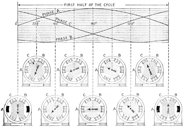
Figs. 1,689 to 1,708.—Sine curves of three phase current and diagrams showing the physical conception of a three phase rotating
magnetic field. The diagrams are constructed in the same manner as explained in figs. 1,664 to 1,683. It should be noted
that the phase windings are arranged in the direction of rotation in the sequence ACB, phase C being wound in opposite
[Pg 1309]
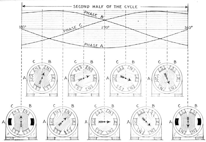
sense to A and B, as indicated by the curves, in that north poles are produced at A and B when the respective curves are
above the zero line, a south pole being produced at C when its curve is above the zero line. The rotation of the resultant
magnetization is clearly seen by following the arrow through its successive positions.
[Pg 1310]
Slip.—Instead of the magnetic needle as was used in the
preceding figures, a copper cylinder may be placed in a rotating
magnetic field and it will be urged also to turn in the same direction
as the rotation of the field.
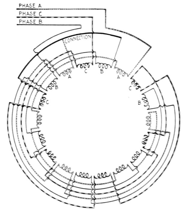
Fig. 1,709.—Diagram of three phase, six pole field winding. There are 18 groups, and the
sequence of phases is ABC in a counter clockwise direction. For a Y connection, the
middle phase is reversed, so that a pole will be formed by the three consecutive phases
when the current is in the same direction in A and C, and opposite in B. The beginning
of the middle coil C, and not the end, as with the other two, is connected to the common
point O. In this case the pole shifts a distance equal to three groups for each alternation,
so that one revolution of the field requires three cycles.
The torque tending to turn the cylinder is due to the induction
of currents of opposite polarity in the cylinder.
For simplicity, the rotating magnetic field may be supposed
to be produced by a pair of magnetic poles placed at opposite
sides of the cylinder and revolved around it as in fig. 1,710.
[Pg 1311]
Now, for instance in starting, the cylinder being at rest any
element or section of the surface as the shaded area AB, will,
as it comes into the magnetic field of the rotating magnet, cut
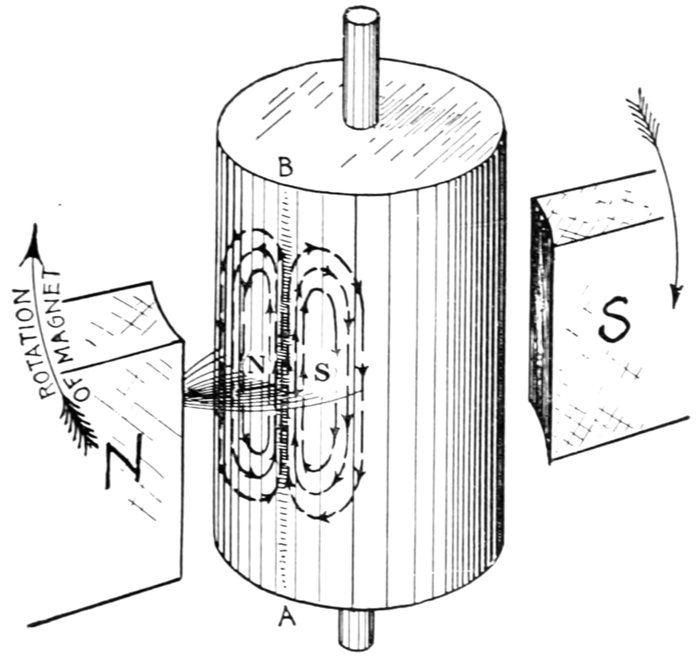
Fig. 1,710.—Copper cylinder and rotating magnet illustrating the principle of operation of an
induction motor. The "rotating magnetic field" which is necessary for induction motor
operation is for simplicity here produced by rotating a magnet as shown. In starting,
the cylinder being at rest, any element as AB, as it is swept by the field will cut magnetic
lines, which will induce a current upward in direction as determined by applying Fleming's
rule (fig. 132, page 133). The inductive action is strongest at the center of the field
hence as AB passes the center the induced pressure along AB is greater than along elements
more or less remote on either side. Accordingly a pair of eddy currents will result as
shown (see fig. 291, page 271). Applying the right hand rule for polarity of these eddy
currents (see fig. 119, page 117) it will be seen that a S pole is induced by the eddy on
the side of the cylinder receding from the magnet, and a N pole by the eddy on the side
toward which the magnet is approaching. The cylinder, then, is attracted in the direction
of rotation of the magnet by the induced pole on the receding side, and repelled in the same
direction by the induced pole on the approaching side. Accordingly, the cylinder begins
to rotate. The velocity with which it turns depends upon the load; it must always turn
slower than the magnet, in order that its elements may cut magnetic lines and induce
poles to produce the necessary torque to balance the load. The difference in speed of
the magnet and cylinder is called the slip. Evidently the greater the load, the greater
is the slip required to induce poles of sufficient strength to maintain equilibrium. The
figure is drawn somewhat distorted, so that both eddies are visible.
[Pg 1312]
magnetic lines of
force inducing a current
therein, whose
direction is easily
determined by applying
Fleming's
rule.[6]
Since the field is
not uniform, but
gradually weakens,
as shown, on either
side of the shaded
area (which is just
passing the center),
the pressure induced
on either side will
be less than that
induced in the shaded
area, giving rise
to eddy currents
(as illustrated in
fig. 291, page 271). These eddy currents induce poles as indicated
at the centers of the whorls, the polarity being determined
by applying the right hand rule (fig. 119, page 117).
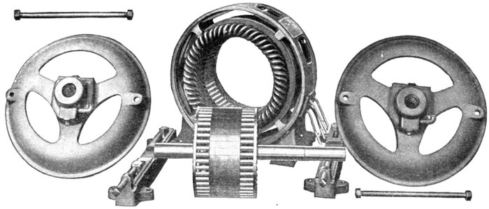
Figs. 1,711 to 1,718.—Parts of Allis-Chalmers polyphase induction motor with squirrel cage armature.
[Pg 1313]
By inspection of fig. 1710, it is seen that the induced pole toward
which the magnet is moving is of the same polarity as the magnet;
therefore it is repelled, while the induced pole from which the
magnet is receding, being of opposite polarity, is attracted. A
torque is thus produced tending to rotate the cylinder.
It must be evident that this torque is greatest when the cylinder
is at rest, because the magnetic lines are cut by any element on
the cylindrical surface at the maximum rate.
Moreover, as cylinder is set in motion and brought up to speed,
the torque is gradually reduced, because the rate with which the
magnetic lines are cut is gradually reduced.
Ques. What is the essential condition for the operation
of an induction motor?
Ans. The armature, or part in which currents are induced, must
rotate at a speed slower than that of the rotating magnetic field.
In the elementary induction motor, fig. 1,710, the cylinder is the
armature, and the rotating magnets are the equivalent of a rotating
magnetic field.
Ques. What is the difference of speed called?
Ans. The slip.
Ques. Why is slip necessary in the operation of an induction
motor?
Ans. If the armature had no weight and there was no friction
offered by the bearings and air, it would revolve in synchronism
with the rotating magnetic field, that is, the slip would be zero;
but since weight and friction are always present and constitute[Pg 1314]
a small load, its speed of rotation will be a little less than that of
the rotating magnetic field, so that induction will take place, in
amount sufficient to produce a torque that will balance the load.
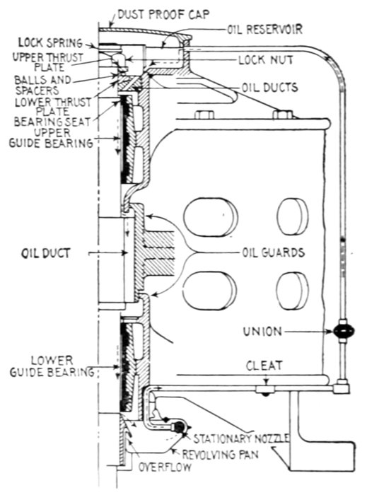
Fig. 1,719.—General Electric vertical type induction motor; sectional view showing oiling
system. It is provided with ball thrust bearings and top and bottom guide bearings, and
a continuous flow of oil is maintained through all the bearings by means of a pump which
is made integral with the motor. The ball thrust bearings are designed to support the
weight of the armature only. In cases where the armature is direct connected a flexible
coupling should be used to prevent additional weight coming on the thrust bearings. In
operation, when the motor starts, the oil, revolving with the pan, flows against the stationary
nozzle and is forced by its velocity at a high pressure through the oil pipe into the
reservoir on top. It then flows down through the ball bearing and upper guide bearing,
through a slot in the armature spider into the lower guide bearing and thence into the
oil pan. Thus a continuous stream of oil is delivered through all bearings.
Ques. How is slip expressed?
Ans. In terms of synchronism, that is, as a percentage of the
speed of the rotating magnetic field.
[Pg 1315]
The slip is obtained from the following formula:
Slip (rev. per sec.) = Sf - Sa
or, expressed as a percentage of synchronism, that is, of the synchronous
speed,
where
- Sf = Synchronous speed, or R.P.M. of the rotatory magnetic field;
- Sa = Speed of the armature.
The synchronous speed is determined the same as for synchronous
motor by use of the following formula:
where
- Sf = Synchronous speed or R.P.M. of the rotating magnetic field;
- P = Number of poles;
- f = frequency.
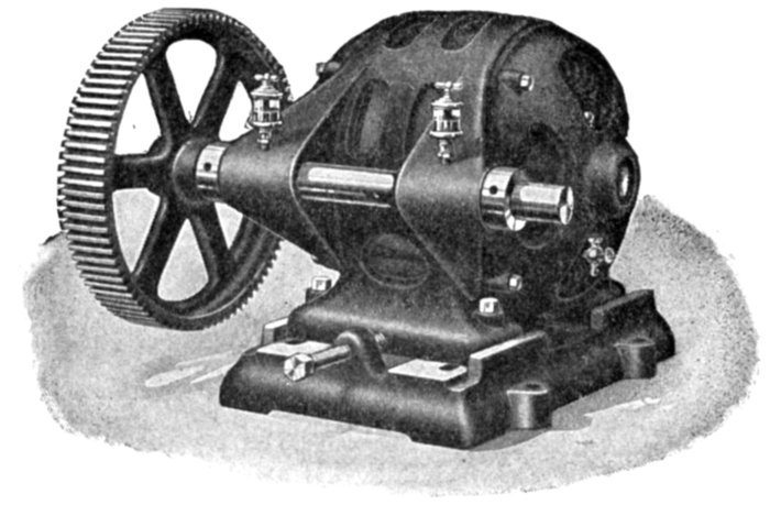
Fig. 1720.—Triumph back geared polyphase induction motor. A great many applications,
especially for direct attachment, require the use of either a very slow or special speed
motor. As these are quite costly, the preferable arrangement, and one equally as satisfactory,
is the use of a standard speed motor combined with a back geared attachment.
Rawhide pinions are furnished whenever possible, insuring smooth running with a minimum
of noise.
[Pg 1316]
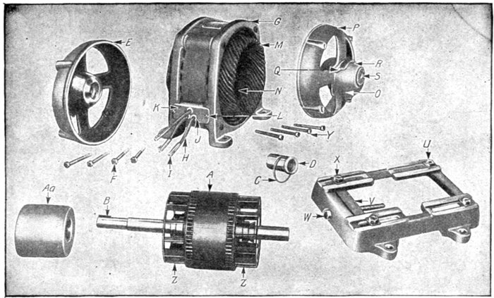
Figs. 1,721 to 1,735.—Parts of General Electric small polyphase induction motors. A, armature; B, key for armature
shaft; C, oil ring; D, bearing lining; E, bearing head, pulley end; F, cap screw for bearing heads; G, field,
complete with winding, terminal plate and leads; H, motor leads; I, terminal connector for motor leads; J, soft
rubber bushing for motor leads; K, terminal plate; L, screw for terminal board; M, field coils; N, wooden top
sticks for field coils; O, oil filler; P, bearing head opposite pulley end; Q, screw for oil well cover; R, oil well
cover; S, socket pipe plug for bearing head; U, motor base; V, yoke for motor base; W, motor base adjusting
screw; X, bolt for motor base and frame (short); Y, cap screw for bearing head; Z, internal directive fan;
Aa, pulley.
[Pg 1317]
The following table gives the synchronous speed for various frequencies
and different numbers of poles:
Table of Synchronous Speeds
| Frequency |
R.P.M. of the rotating magnetic field, when number of poles is |
| 2 |
6 |
10 |
16 |
20 |
24 |
| 25 |
1,500 |
500 |
300 |
188 |
150 |
125 |
| 60 |
3,600 |
1,200 |
720 |
450 |
360 |
300 |
| 80 |
4,800 |
1,600 |
960 |
600 |
480 |
400 |
| 100 |
6,000 |
2,000 |
1,200 |
750 |
600 |
500 |
| 120 |
7,200 |
2,400 |
1,440 |
900 |
720 |
600 |
| 125 |
7,500 |
2,500 |
1,500 |
938 |
750 |
625 |
Ques. How does the slip vary?
Ans. It varies from about 1 per cent. in a motor designed
for very close regulation to 40 per cent. in one badly designed,
or designed for some special purpose.
Ques. Why is the slip ordinarily so small?
Ans. Because of the very low resistance of the armature,
very little pressure is required to produce currents therein, of
sufficient strength to give the required torque. Hence, the
necessary rate of cutting the magnetic lines to induce this pressure
in the armature is reached with very little difference between
the field speed and armature speed, that is, with very little slip.
Ques. How does the slip vary with the load?
Ans. The greater the load the greater the slip.
In other words, if the load increase, the motor will run slower, and
the slip will increase. With the increased slip, the induced currents
and the driving force will further increase. If the motor be well designed
so that the field strength is constant and the lag of the armature
currents is small, the driving force developed or torque will be proportional
to the slip, that is the slip will increase automatically as the
load is increased, so that the torque will be proportional to the load.
[Pg 1318]
According to Weiner, the slip varies according to the following table:
SLIP OF INDUCTION MOTORS
| Capacity of motor H. P. |
Slip at full load per cent. |
Capacity of motor H. P. |
Slip at full load per cent. |
| Usual limits |
Average |
Usual limits |
Average |
| ⅛ |
20 to 40 |
30 |
15 |
5 to 11 |
8 |
| ¼ |
10 " 30 |
20 |
20 |
4 " 10 |
7 |
| ½ |
10 " 20 |
15 |
30 |
3 " 9 |
6 |
| 1 |
8 " 20 |
14 |
50 |
2 " 8 |
5 |
| 2 |
8 " 18 |
13 |
75 |
1 " 7 |
4 |
| 3 |
8 " 16 |
12 |
100 |
1 " 6 |
3.5 |
| 5 |
7 " 15 |
11 |
150 |
1 " 5 |
3 |
| 7½ |
6 " 14 |
10 |
200 |
1 " 4 |
2.5 |
| 10 |
7 " 12 |
9 |
300 |
1 " 3 |
2 |
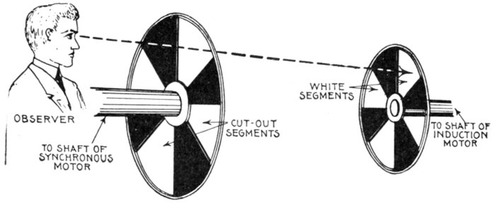
Fig. 1,736.—Sector method of measuring the slip of induction motors. A black disc having
a number of white sectors (generally the same as the number of poles of the induction
motor) is fastened with wax to shaft of the induction motor, and is observed through
another disc having an equal number of sector shaped slits (that is a similar disc with the
white sectors cut out) and attached to the shaft of a small self-starting synchronous motor,
which is fitted with a revolution counter that can be thrown in or out of gear at will; then
the slip (in terms of Nr) = N ÷ (Ns ÷ Nr), in which: N = number of passages of the
sectors; Ns = number of sectors; Nr = number of revolutions recorded by the counter
during the interval of observation. For large values of slip, the observations may be
simplified by using only one sector (Ns = 1), then N will equal the slip in revolutions.
[Pg 1319]
Ques. Describe one way of measuring the slip.
Ans. A simple though rough way is to observe simultaneously
the speed of the armature and the frequency, calculating
the slip from the data thus obtained, as on page 1,315.
This method is not accurate, as, even with the most careful readings,
large errors cannot be avoided. A better way is shown in fig. 1,736.
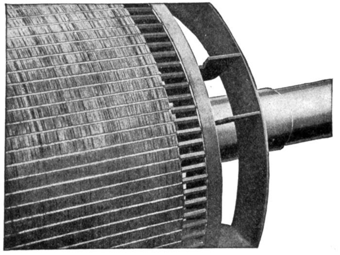
Fig. 1,737.—Detail of Westinghouse squirrel cage armature for induction motor. This is
an example of cast on construction similar to that of Morse-Fairbanks (see figs. 1,752, 1,753
and 1,915). The inductors are embedded in a special cement.
Evolution of the Squirrel Cage Armature.—In the early
experiments with rotating magnetic fields, copper discs were used;
in fact, it was then discovered that a mass of copper or any conducting
metal, if placed in a rotating magnetic field, will be urged
in the direction of rotation of the field.
Ferraris used a copper cylinder as in figs. 1,710 and 1,738,
which was the first step in the evolution of the squirrel cage
armature. The trouble with an armature of this kind is that
there is no definite path provided for the induced currents.
[Pg 1320]
[Pg 1321]
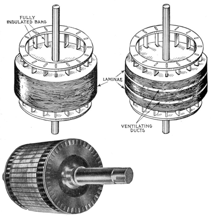
Figs. 1,738 to 1,744.—Evolution
of the squirrel cage armature.
The early experiments of Arago,
Herschel, Babbage and Baily
demonstrated that a mass of
copper or any conducting metal,
if placed in a revolving magnetic
field, will be urged to revolve
in the direction of the
revolving field. They used
discs, but Ferraris used a copper
cylinder as shown in figs.
1,710 and 1,738; this was the first squirrel cage
armature. Figs. 1,739 to 1,744 show the gradual
development of the primitive device shown in fig.
1,738; fig. 1,739, Ferraris' cylinder with slots restricting
the path of induced currents; fig. 1,740,
Dobrowolsky's so called squirrel cage which he
embedded in a solid iron core, as in fig. 1,741;
fig. 1,742, design with insulated bars and laminated core to prevent eddy currents in the
core; fig. 1,743, laminated core with ventilating ducts; fig. 1,744, modern squirrel cage
armature representing the latest practice as built by Mechanical Appliance Co. The core
is built up of discs punched from No. 29 gauge electrical sheet, insulated from each other
and firmly clamped between end plates locked on the shaft. The slots in the discs are
of the same general form as those in the core. Heavy fibre end pieces, punched to match
the discs are placed at each end of the core, to prevent the bars coming in contact with
the sharp edges of the teeth. The winding is made up of rectangular copper bars, passing
through slots in the core, and short circuited on each other by means of copper end rings
of special design. The bars are pressed into holes punched in the end rings, and the contact
is then protected from corrosion by being dipped in a solder bath. The bars are insulated
from the iron of the core by fibre cell projecting beyond the end of the slot. To
secure ventilation the short circuiting rings are set some distance from the end of the
core. In this way the bars between the core and the ring act as the vanes of a pressure
blower, forcing a large volume of air through the field coils and ventilating openings.
[Pg 1322]
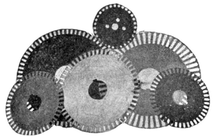
Fig. 1,745.—Mechanical Appliance Co. solid core discs as used on small and medium size
induction motors.
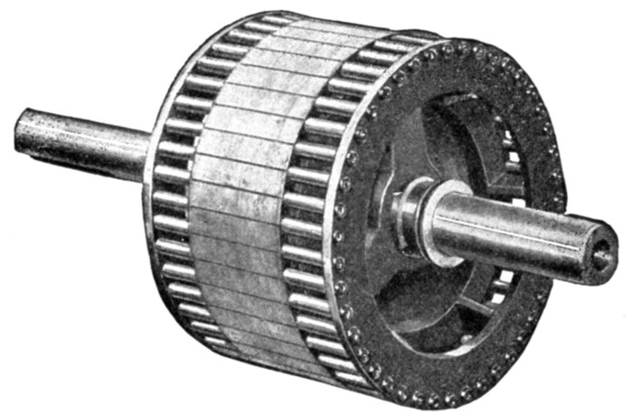
Fig. 1,746.—Allis-Chalmers squirrel cage armature construction. The core laminæ are
mounted on a cast iron spider having arms shaped to act as fan blades for forcing air
through the motor. The spider is pressed on to the shaft. In the smallest sizes the punchings
are mounted directly on the shaft, which is properly machined to hold them firmly.
Copper bars are used as inductors in the larger sizes, and copper rods in the smaller sizes.
The ends of the inductors are turned down somewhat smaller than the body and fit in
holes in the end rings. The shoulder thus formed fits firmly against the end rings. Good
electrical contact is obtained by expanding the inductors in the end ring holes. In large
armatures both bars and end rings are of rectangular cross section, the bars and rings
being fastened by machine steel cap screws.
Obviously, a better result is obtained if, in fig. 1,738, the downward
returning currents of the eddies are led into some path
where they will return across a field of opposite polarity from[Pg 1323]
that across which they ascended, as in such case, the turning
effect will be doubled. Accordingly the design of fig. 1,738 was
modified by cutting a number of parallel slits which extended
nearly to the ends, leaving at each end an uninterrupted "ring" of
metal. This may be called the first squirrel cage armature, and
in the later development Dobrowolsky was the first to employ
a built-up construction, using a number of bars joined together
by a ring at each end, as in fig. 1,740, and embedded in a solid
mass of iron, as in fig. 1,741; he regarding the bars merely as
veins of copper lying buried in the iron.
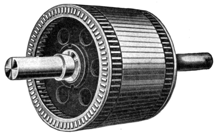
Fig. 1,747.—Triumph squirrel cage armature. In construction thin sheet steel laminations,
japanned, are built up to form the core, and are rigidly clamped together by heavy malleable
iron end plates. Semi-enclosed slots are punched in the outer periphery to receive the
windings, so that none of the centrifugal force is carried by the inductors. These inductors
are set edge on, and are riveted and soldered into resistance rings. These rings
are punched to receive the inductors in such a manner that there is an unbroken strip of
metal completely surrounding them. Moreover, the short circuiting rings are set some
distance from the end of the core, so that the inductors between the core and ring act as
vanes to force air through the coils for ventilation.
[Pg 1324]
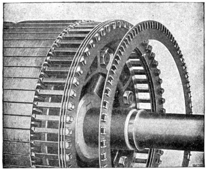
Fig. 1,748.—General Electric soldered form of end ring construction on squirrel cage armatures.
The armature inductors or copper bars laid in the core slots are short circuited by
these end rings, which are also made of copper. For the smaller sizes the rings are thin,
but of considerable radial depth and are held apart by spacing washers. They have rectangular
holes punched near their outer peripheries through which the bars pass. Lips are
formed on the rings, as shown, to which the bars are soldered.
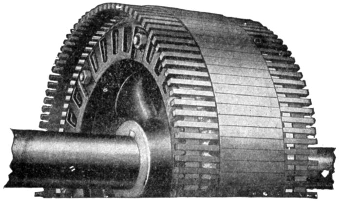
Fig. 1,749.—General Electric welded form of end ring construction on squirrel cage armatures.
Space limitations make it difficult to provide multiple soldered rings of sufficient area for
large motors; hence, on such machines welding is resorted to, as shown. The ring in welded
construction is placed beneath the bars at each end of the armature. Short radial bars
are welded to the edges of these rings and to the inductors or squirrel cage bars, thereby
making good electrical contact.
[Pg 1325]
A solid cylinder of iron will of course serve as an armature, as it is
magnetically excellent; but the high specific resistance of iron prevents
the flow of induced currents taking place sufficiently copiously; hence
a solid cylinder of iron is improved by surrounding it with a mantle of
copper, or by a squirrel cage of copper bars (like fig. 1,740), or by
embedding rods of copper (short circuited together at their ends with
rings) in holes just beneath its surface. However, since all eddy currents
that circle round, as those sketched in fig. 1,738, are not so efficient in
their mechanical effect as currents confined to proper paths, and as they
consume power and spend it in heating effects, the core was then
constructed with laminations lightly insulated from each other, and
further the squirrel cage copper bar inductors were fully insulated
from contact with the core. Tunnel slots were later replaced by designs
with open tops.
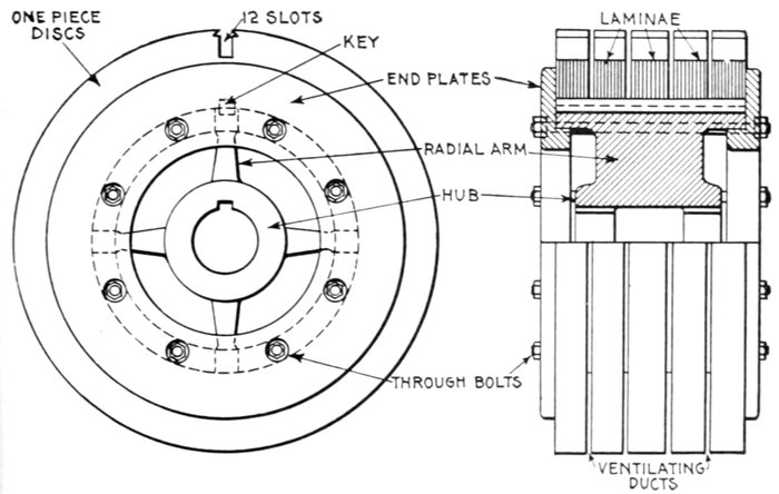
Figs. 1,750 and 1,751.—Built up core construction with discs punched in one piece. The
spider proper consists of a hub provided with four radial arms, which fit the inner diameter
of the disc. The hub is bored out so that it fits very tightly on the shaft, and a key is
provided to avoid any chance of turning. The core disks are clamped firmly in place
by two heavy cast iron end plates which are pressed up and held by the bolts. These
bolts pass under the discs, so that there is no danger of their giving rise to eddy currents.
The key not only prevents the discs turning on the spider but also ensures the alinement of
discs, which is necessary to make the teeth form smooth slots when the core is assembled.
Fig. 1,744 shows a modern squirrel cage armature conforming to the
latest practice, other designs being illustrated in the numerous accompanying
cuts.
In the smaller sizes, the core laminæ are of the solid type as shown
in fig. 1,745, but for larger motors the core consists of a spider and
segmental discs as shown in figs. 1,750 and 1,751.
Fig. 1,748 shows a soldered form of end ring construction, and figs.
1,752 and 1,753 the method of welding the end ring to the inductors.
[Pg 1326]
The Field Magnets.—The construction of the field magnets,
which, when energized with alternating current produce the
rotating magnetic field, is in many respects identical with the
armature construction of revolving field alternators.
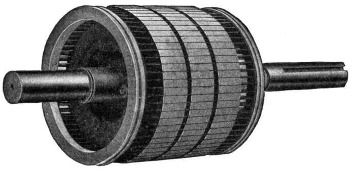
Fig. 1,752.—Fairbanks-Morse squirrel cage armature with cast-on rings showing inspection
grooves. The method consists in fusing the ends of the inductors into an end ring of a
special composition, thereby producing a perfect electrical and mechanically strong joint.
In this process the armature with its bars in place is put into a mould and the molten
metal poured around the inductors, melting their ends and effectually fusing them into
the body of the ring. The ring is then turned down to finished size and polished. An inspection
groove is cut as shown to indicate that the fusion is complete and the joint perfect.
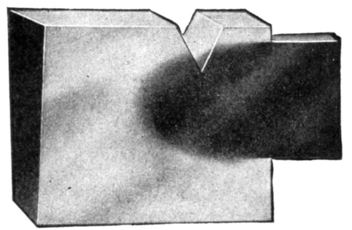
Fig. 1,753.—Section of Fairbanks-Morse "cast-on" joint showing union of end ring and inductor.
The view shows the V-shape inspection groove as described in fig. 1,752.
[Pg 1327]
Broadly, the field magnets of induction motors consists of:
- 1. Yoke or frame;
- 2. Laminæ, or core stampings;
- 3. Winding.
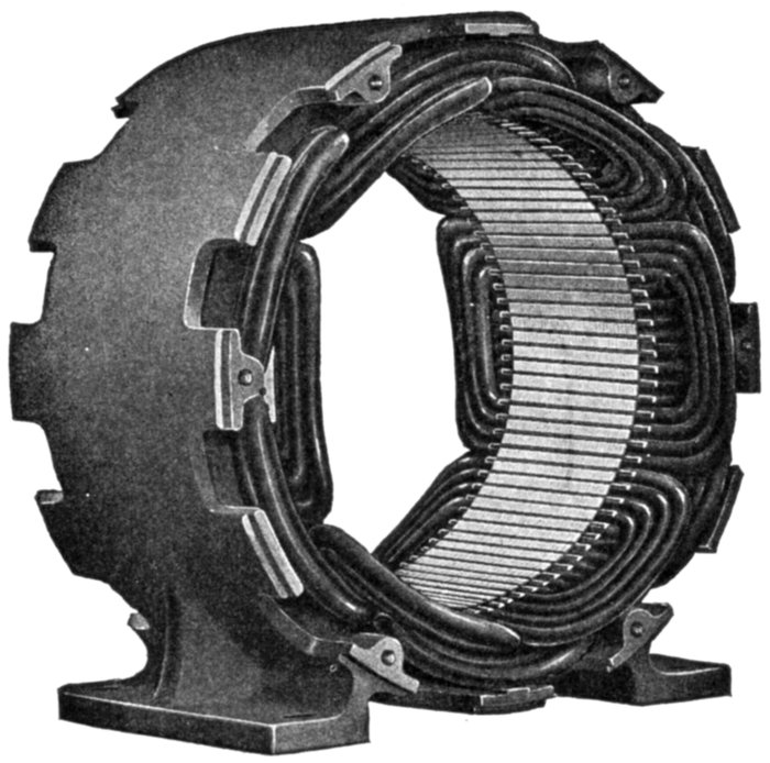
Fig. 1,754.—Richmond field construction for polyphase induction motors, showing style of
winding for use with squirrel cage and wound armature types.
Ques. What is the construction of the yoke and
laminæ?
Ans. They are in every way similar to the armature frame
and core construction of revolving field alternators.
[Pg 1328]
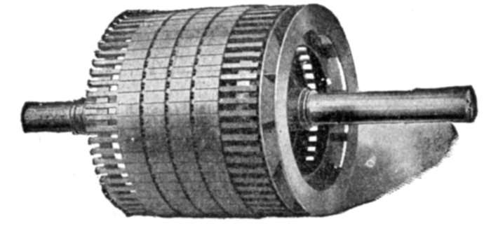
Fig. 1,755.—Western Electric squirrel cage armature of high speed induction motor
for centrifugal pump service. This armature is an example of heavy duty construction.
The inductors are welded to the short circuiting end rings, the latter being located
beneath the inductors, as shown. Fan vanes are provided at one end for ventilation.
In the field construction, the core laminations are assembled in a closed box frame, and
clamped by heavy rings while under hydraulic pressure. The stator coils are form wound
and subjected to a special insulating process, which renders them especially impervious
to moisture, and capable of operating without breakdown in locations which are too
damp for ordinary motors. The bearing brackets are of rigid mechanical construction,
and the pulley end bracket and bearings of all sizes are split to facilitate removal of the
rotor and complete inspection. These machines range in size from 50 to 200 horse power,
the rugged construction adapting them to heavy and severe service, such as is met with
in mining, the construction of dams, canals, aqueducts, tunnels, etc.
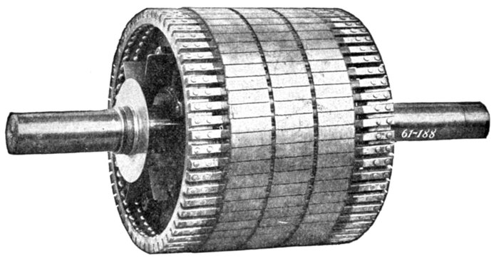
Fig. 1,756.—Wagner squirrel cage armature for polyphase induction motor, as employed on
motors of from 5 to 25 horse power. The features of construction as seen in the illustration
are bar inductors, ventilating passages through the core laminæ, riveted connection
between inductors and end rings ventilating vanes on end plate, extra large end rings.
The object of making the rings unusually large is to make the resistance of the rings lower
than is desirable for some classes of service, in order to obtain motors having minimum
slip, increased efficiency, and maximum overload capacity under normal operation. When
the torque required by some very unusual and entirely abnormal installation exceeds that
of the average conditions, it is an easy matter to reduce the section of the end rings, by turning
them down in a lathe, thereby increasing the resistance and starting torque.
[Pg 1329]
Field Windings for Induction Motors.—The field windings
of induction motors are almost always made to produce
more than two poles in order that the speed may not be unreasonably
high. This will be seen from the following:
If P be the number of pairs of poles per phase, f, the frequency, and
N, the number of revolutions of the rotating field per minute, then
Thus for a frequency of 100 and one pair of poles, N = 60 × 100 ÷
1 = 6,000. By increasing the number of pairs of poles to 10, the frequency
remaining the same, N = 60 × 100 ÷ 10 = 600. Hence,
in design, by increasing the number of pairs of poles the speed of the
motor is reduced.
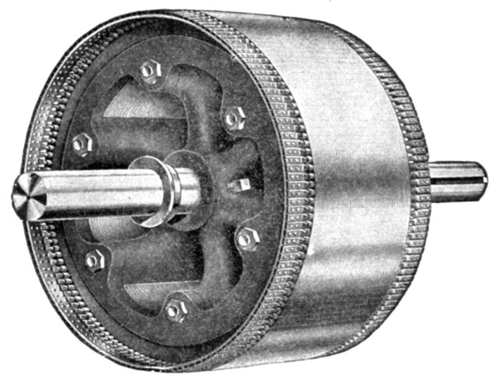
Fig. 1,757.—Richmond squirrel cage armature. The copper bars are double riveted at either
end to the resistance rings, then dipped into a solder bath.
Ques. State an objection to very high speed of the
rotating field.
Ans. The more rapid the rotation of the field, the greater is
the starting difficulty.
[Pg 1330]
Ques. Besides employing a multiplicity of poles, what
other means is used to reduce the speed?
Ans. Reducing the frequency.
Ques. What difficulty is encountered with low frequency
currents?
Ans. If the frequency be very low, the current would not be
suitable for incandescent lamp lighting, because at low frequency
the rise and fall of the current in the lamps is perceptible.

Fig. 1,758.—Field construction of Crocker-Wheeler induction motor with magnetic bridge.
Steel bridges are inserted in the grooves where the coils are placed, to protect them from
dirt and mechanical injury and at the same time provide a path for the magnetic flux
which has a more uniform reluctance, thereby insuring a better distribution of the flux
in the air gap and at the same time retaining open slot construction from which the coils
can be readily removed.
Ques. What is the general character of the field
winding?
Ans. The field core slots contain a distributed winding of
substantially the same character as the armature winding of a
revolving field polyphase alternator.
[Pg 1331]
Ques. Are the poles formed in the usual way?
Ans. They are produced by properly connecting the groups
of coils and not by windings concentrated at certain points on
salient or separately projecting masses of iron, as in direct
current machines.
Ques. How are the coils grouped?
Ans. Three phase windings are usually Y connected.
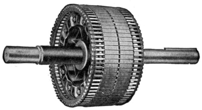
Fig. 1,759.—Western Electric squirrel cage armature. The inductors consist of solid copper
bars embedded in the slots of a laminated core, with their projecting ends securely fitted
and soldered to heavy copper rings.
Ques. What other arrangement is sometimes used?
Ans. In some cases Y grouping is used for starting and Δ
grouping for running.
Starting of Induction Motors.—It must be evident that
if the field winding of an induction motor whose armature is at
rest, be connected directly in the circuit without using any
starting device, the machine is placed in the same condition as a
transformer with the secondary short circuited and the primary
connected to the supply circuit. Owing to the very low resistance[Pg 1332]
of the armature, the machine, unless it be of very small size,
would probably be destroyed by the heat generated before it
could come up to speed. Accordingly some form of starting device
is necessary. There are several methods of starting, as with:
- 1. Resistances in the field;
- 2. Auto-transformer or compensator;
- 3. Resistance in armature.
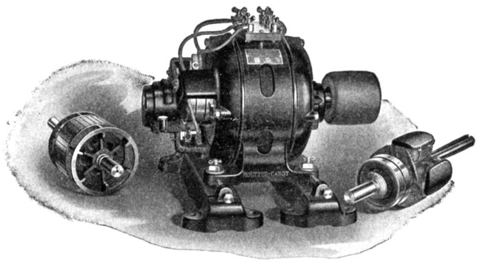
Fig. 1,760.—Holzer Cabot combination polyphase induction motor set, consisting of wound
frame and three rotors: 1, squirrel cage armature, 2, wound armature, 3, rotating field.
The set is intended for school demonstration of induction motor phenomena. The motor
operating with the squirrel cage armature has an inherent constant speed characteristic and
on brake tests will show its exceptionally strong starting torque and ability to take excessive
overloads. This motor can be used as a generator also, in the sense that if connected to the
line and driven above synchronous speed by some external means, it will act as an asynchronous
generator and return power to the line. For variable speed service, an armature
having a winding upon it similar to that on the frame must be used. External resistances
inserted in the armature circuit may be used to produce, first, a reduction of starting current,
second, an increase of starting torque, or third, a variation of speed. Thus an extensive
list of experiments can be performed with this phase wound armature directly along
the line of present engineering practice. The phase wound armature can be used as an
alternator in the same sense as mentioned above for the squirrel cage machine. For
synchronous motor and three phase operation the revolving field with projecting poles
and slip rings would be used, the field being excited from a direct current supply.
Ques. Explain the method of inserting resistances in
the field.
Ans. Variable resistances are inserted in the circuits leading
to the field magnets and mechanically arranged so that the[Pg 1333]
resistances are varied simultaneously for each phase in equal
amounts. These starting resistances are enclosed in a box
similar to a direct current motor rheostat.
Ques. Is this a good method?
Ans. It is more economical to insert a variable inductance
in the circuit, by using an auto-transformer.
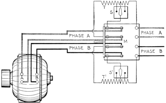
Fig. 1,761.—Westinghouse auto-starter. Polyphase induction motors may be started by
connecting them directly to the circuit with an ordinary switch, and the smaller motors
are started in this way in practice. In the larger motors, however, the starting torque
at normal voltage is several times its full load torque; therefore, they are started on a
reduced voltage, and the full pressure of the circuit is not applied until they have practically
reached their operating speed. The figure shows connections with a two phase
alternating current circuit. The auto-starter consists of two auto-transformers T and T',
each having only a single winding for both primary and secondary, which are tapped at
certain points by switches, thus dividing the winding into a number of loops, so that one
of several voltages may be applied for starting, and the starting torque thus adjusted to
the work that has to be performed. At the highest points tapped by the switches S, and
S', the full pressure, and at the lowest points, the lowest pressure, is applied to the motor
by the operation of the main switch M. This switch has four blades and three positions.
When thrown to the left as indicated, it connects the auto-transformers T and T',
across the circuits A and B respectively, so that the pressure across the transformer
coils, as determined by the position of the switches S and S', is applied to the motor circuits
A and B. The intermediate position of the switch M interrupts both circuits. To start the
motor, the switch M is thrown to the left and a reduced pressure applied; after the motor
has started and come up to speed the switch M is thrown to the right, thus cutting out
the transformer and connecting the motor directly to the circuit. The starting device
can be located at a point remote from the motor, thus eliminating danger from fire due
to possible sparks, in case where it is necessary to install the motors in grain elevators,
woolen mills, or in any place exposed to inflammable gases, or floating particles of combustible
matter. This feature is also valuable in cases where motors are suspended from the
ceiling, or installed in places not easily accessible.
[Pg 1334]
Ques. What is the auto-transformer or compensator
method of starting?
Ans. It consists of reducing the pressure at the field terminals
by interposing an impedance coil across the supply circuit
and feeding the motor from variable points on its windings.
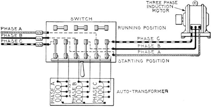
Fig. 1,762.—Auto-transformer or compensator connections for three phase induction motor.
In operation when the double throw switch is thrown over to starting position, the
current for each phase of the motor flows through an auto-transformer, which consists of a
choking coil for each phase, arranged so that the current may be made to pass through
any portion of it (as 1, 2, 3) to reduce the voltage to the proper amount for starting. After
the motor has come up to speed on the reduced voltage, the switch is thrown over to
running position, thus supplying the full line voltage to the motor. [7]In actual construction
fuses are usually connected, so that they will be in circuit in the running position, but not
in the starting position, where they might be blown by the large starting current.]
Internal Resistance Induction Motors.—The armature
of this type of induction motor differs from the squirrel cage
variety in that the winding is not short circuited through copper
rings, but, in starting, is short circuited through a resistance
mounted directly on the shaft in the interior of the armature.
When the motor is thrown in circuit, a very low starting current is drawn
from the line due to the added resistance in the armature. As the motor
comes up to speed, this resistance is gradually cut out, and at full speed
the motor operates as a squirrel cage motor, with short circuited winding.
[Pg 1335]
Ques. How is the resistance gradually cut out in
internal resistance motors?
Ans. By operating a lever which engages a collar free to
slide horizontally on the shaft. The collar moves over the
internal resistance grids (located within the armature spider),
thus gradually reducing their value until they are cut out.
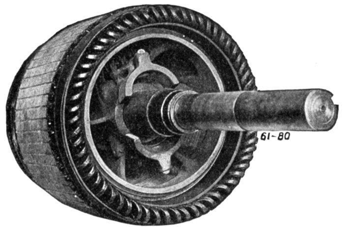
Fig. 1,763.—View of armature interior of Wagner polyphase induction motor with wound
armature, showing the centrifugal device which at the proper speed short circuits all the
coils, transforming the motor to the squirrel cage type. The winding is connected with
a vertical "commutator" so called. Inside the armature are two governor weights, which
are thrown outwards by the centrifugal force when the machine reaches the proper speed,
thus pushing a solid copper ring (which encircles the shaft) into contact with the inner
ends of the "commutator" bars, thus completely short circuiting the armature winding.
Ques. For what size motors is the internal resistance
method suited?
Ans. Small motors.
Ques. Why is it not desirable for large motors?
Ans. The excessive I2R loss in the resistances, if confined
within the armature spider, would produce considerable heating,
and on this account it is best placed external to the motor.
[Pg 1336]
Ques. On what class of circuit are internal resistance
motors desirable?
Ans. On circuits devoted to lighting service as well as power
service, where a high degree of voltage regulation is essential.
The initial rush of current when a squirrel cage motor is thrown on the
line is more or less objectionable and there are central stations which
allow only resistance type of induction motor to be used on their lines.
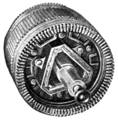
Fig. 1,764.—Western Electric wound armature for internal resistance induction motor. In
starting the inductors are short circuited through a resistance which is gradually cut out
as the motor comes up to speed.
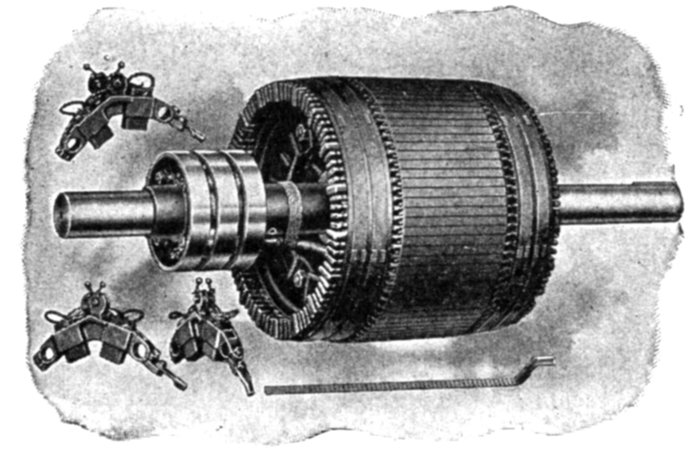
Figs. 1,765 to 1769.—Western Electric wound armature for external resistance, or slip ring
induction motor, showing brush rigging, slip rings and bar winding.
External Resistance or Slip Ring Motors.—In large
machines, and those which must run at variable speed, such as
is required in the operations of cranes, hoists, dredges, etc., it is[Pg 1337]
advisable that the regulating
resistances be placed externally
to the motor. Motors
having this feature are commercially
known as slip ring
motors, because connections
are made between the external
resistances and the armature inductors
by means of slip rings.
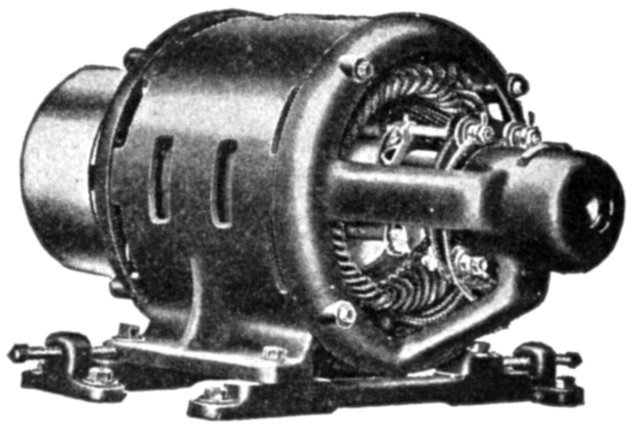
Fig. 1,770.—Richmond slip ring motor.
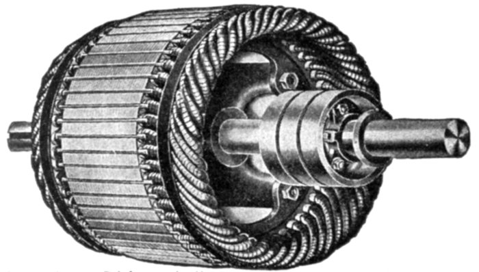
Fig. 1,771.—Richmond slip ring armature as used on motor
in fig. 1,770.
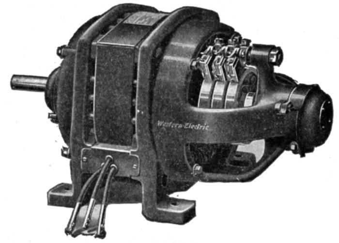
Fig. 1,772.—Western Electric
riveted frame slip ring
induction motor for variable
speed service; adapted
either to continuous or
intermittent operation.
As with the internal resistance
motor the
armature winding of
a slip ring motor is
not short circuited
through copper
rings in starting,
but through a resistance,
which in this
case is located externally.
Ques. How
is the armature
winding
connected?
Ans. It is
connected in Y
grouping and
the free ends
connected to the
slip rings, leads
going from the
brushes to the[Pg 1338]
variable external resistances, these being illustrated in fig. 1,779.
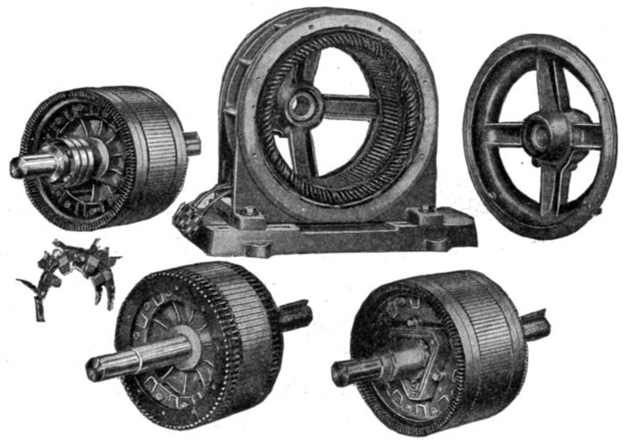
Figs. 1,773 to 1,778.—Sprague skeleton type motor frame with various types of armature.
Fig. 1,777, plain squirrel cage armature; fig. 1,778, internal resistance armature; fig.
1,773 slip ring armature. In the construction of the plain squirrel cage armature, fig. 1,777,
copper bars are inserted in the slots of the core, and are insulated from the core by enclosing
tubes which project about one-half inch beyond the iron at each side. The bars
are short circuited at their ends by copper rings. These rings are thin, but of considerable
radial depth and are held apart by spacing washers. They have rectangular holes punched
near their outward periphery, through which the armature bars pass, and to which they are
soldered. The internal resistance armature, fig. 1,778, is provided with a phase winding,
starting (internal) resistance, and switch located on the shaft. The starting resistance is designed
to give approximately full load torque with full load current at starting. A greater
torque than full load torque can be obtained for starting, if required, by cutting out resistance.
The resistance consists of cast iron grids enclosed in a triangular cover which is bolted
to the end plates holding the armature laminæ together, and is short circuited by sliding
laminated spring metal brushes along the inside surface of the grids. The brushes are
supported by a metal sleeve sliding on the shaft which is operated by a lever secured to
the bearing bracket and located just above the bearing. A rod passing through the end of
the shaft operates the short circuiting arrangement in sizes up to about 25 horse power.
The external resistance or slip ring armature, fig. 1,773, is similar in construction to fig.
1,778, with the exception that slip rings are provided because of the external location
of the resistance. These rings connect the inductor through brushes to a controlling and
external resistance, two or more carbon brushes being provided for each ring, as in fig. 1,776.
Single Phase Induction Motors.—The general utility of
single phase motors, particularly the smaller sizes, is constantly[Pg 1339]
being enlarged by
the growing practice
of central
stations generating
polyphase current,
of supplying their
lighting service
through single
phase distribution,
and permitting the
use of single phase
motors of moderate
capacity on
the lighting
circuit.
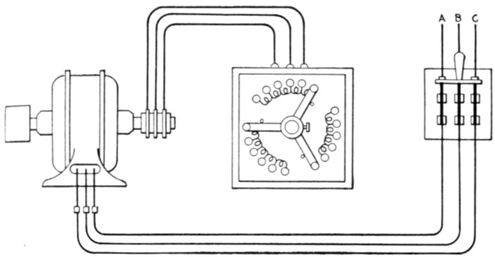
Fig. 1,779.—External resistance or slip ring induction motor connections. The squirrel
cage armature winding is not short circuited by copper end rings, but connected in
Y grouping and the three free ends connected to three slip rings, leads going from the
brushes to three external resistances, arranged as triplex rheostat having three arms rigidly
connected as shown, so that the three resistances may be varied simultaneously and in
equal amounts.
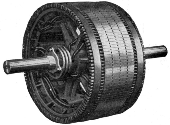
Fig. 1,800.—Allis-Chalmers phase wound external resistance type or slip ring armature construction.
The winding is for three phases and the terminals are brought out to three slip
rings. The front bracket is slightly modified to make room for these rings on the inside.
For starting duty sufficient resistance is supplied to reduce the starting current taken by
the motor to 1¼ times the normal full load current. In the running position the resistance
is all cut out of the circuit. For speed regulation sufficient resistance is supplied to
reduce the speed 50% on normal full load torque.
[Pg 1340]

Figs. 1,801 to 1,828.—Disassembled view of Western Electric three phase external resistance or slip ring mill type induction
motor. It is adapted to severe working conditions, such as are met with in steel mills, crane and hoist service, etc. Designed
for 220 or 440 volt, 25 cycle circuits. The frame is divided horizontally into an upper and a lower steel casting, both of
which are bolted together at the corners by four heavy bolts. The lower casting is provided with four feet for bolting the
motor to its foundation. The end of the upper frame which covers the slip rings is equipped with malleable iron covers
held in place by lock bolts. The field and armature are of the usual construction. One end of the armature winding is
protected against mechanical injury by the slip rings which are of heavy construction and of practically the same diameter
as the armature, and the other end by a detachable flange of the same diameter as the outside of the winding. The slip
rings are mounted on the same spider as the armature, so that the shaft can be removed without disturbing any of the
connections. The brushes are equipped with riveted pigtails, and held in brass brush boxes machined to gauge. Heavy
coiled clock springs are used to maintain an even pressure of the brushes on the slip rings. The armature leads are brought
out through holes in the upper half of the frame, and the field leads are brought through a block, which fits in an opening in
the upper edge of the lower half.
The simplicity
of single phase
systems in comparison
with polyphase
systems,
makes them more
desirable for small
alternating current
plants.
The disadvantage
of single phase
motors is that they
are not self-starting.
A single phase
motor consists
essentially of an
armature and field
magnet having a
single phase winding
and also some phase
splitting arrangement
for starting.
[Pg 1341]
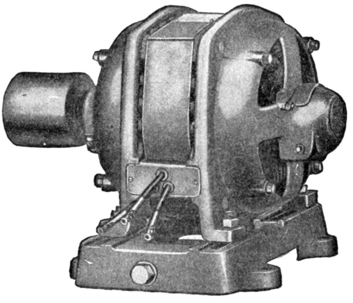
Fig. 1829.—General Electric single phase induction motor. It is suitable for constant speed
service where full load torque at starting does not exceed 140 per cent., and in general is
adapted to drive all geared and belted machinery requiring constant speed with light or
moderate starting torque.
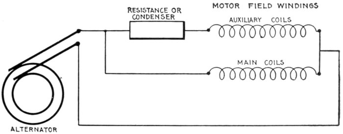
Fig. 1,830.—Simplified diagram showing the principle of phase splitting for starting single
phase induction motors. By the use of an auxiliary set of coils connected in parallel with
the main coils and having in series a resistance or condenser as shown, the single phase
current delivered by the alternator is "split" into two phases, which are employed to
produce a rotating field on which the motor is started.
[Pg 1342]
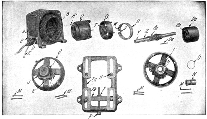
Figs. 1,831 to 1,850.—Parts of Sprague single phase clutch type induction motor. The armature is of
the high resistance smooth core squirrel cage type, the core laminæ being assembled upon a steel
sleeve. On starting the armature revolves freely around the shaft on roller bearings until it
accelerates to about 75% of its rated speed, when a centrifugal clutch engages with an outer shell
keyed directly on the shaft, thus throwing on the load. This type of motor is adapted to drive all
belted, geared, or direct connected machinery requiring constant speed with moderate starting
torque, such as generators, blowers, line shafting in machine shops and factories, drill presses,
laundry machinery, baking machinery, and the like. When greater torque is required at the
moment of starting type RI motors should be used, or clutch couplings may be installed between
the motor and the machine it is to drive. The parts are as follows; A, field frame; B, field coils;
C, terminal block; D, terminal block screws; E, connectors; F, bearing head pulley end; G, bearing
head opposite pulley end; H, motor clamping bolts; I, oil well cover; J, oil well plug; K, drain
plug; L, oil filter; M, cap bolts; N, bearing lining; O, oil ring; P, belt tightener screw; Q, armature
core; R, latch; S, driving shell; T, driving shell set screw; U, clutch ring; V, clutch ring spring;
W, spring adjusting screw; X, nut for belt tightener screw; Y, shaft; Z, driving shell key; Aa,
armature bearing; Ba, pulley; Ca, pulley set screw; Da, pulley key; Ea, sliding base; Fa, yoke.
Ques. Why is a single phase motor not self-starting?
Ans. Because the nature of the field produced by a single
phase current is oscillating and not rotating.
Ques. How is a single phase motor started?
Ans. By splitting the phase, a field is set up normal to the[Pg 1343]
axis of the armature, and nearly 90° displaced in phase from the
field in that axis. This cross field produces the useful torque.
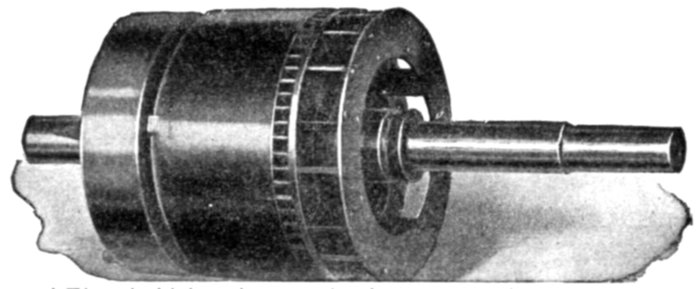
Fig. 1,851.—General Electric high resistance clutch type smooth core squirrel cage armature
of single phase induction motor. The core laminæ are slotted near the circumference to
retain the bar inductors, which extend beyond the core at either end where they are permanently
connected to heavy short circuiting rings.
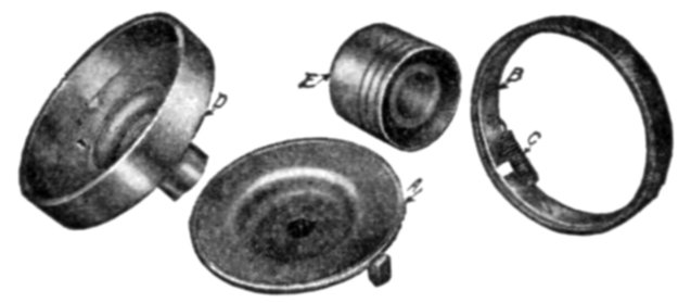
Figs. 1,852 to 1,855.—Parts of General Electric centrifugal clutch pulley as used on clutch
type, single phase induction motor. A, clutch; B, friction band; C, adjusting spring;
D, outer clutch shell with pulley sleeve; E, solid removable pulley; F, internal mechanism
comprising parts A, B, and C; G, outer shell and pulley comprising parts D and E.
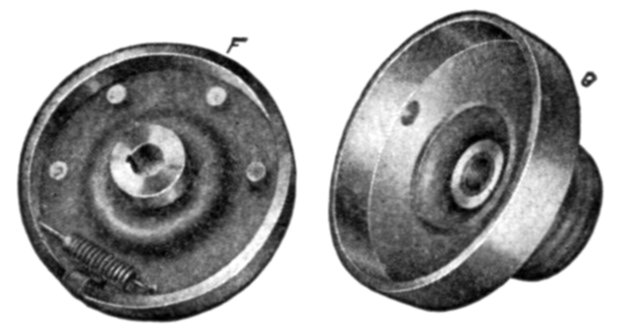
Figs. 1,856 and 1,857.—Partly assembled clutch pulley. F, internal mechanism comprising
parts A, B, C, of fig. 1,852. G, outer shell and pulley, comprising parts D and E of fig. 1,852.
Phase Splitting; Production of Rotating Field from
Oscillating Field.—As previously stated, an oscillating field,
that is, one due to a single phase current, does not furnish any
starting torque. It is therefore necessary to provide a rotating[Pg 1344]
field for a single phase induction motor to start on, which, after
the motor has come up to speed, may be cut out and the motor
will then operate with the oscillating field.
A rotating field may be obtained from single phase current by
what is known as splitting the phase.
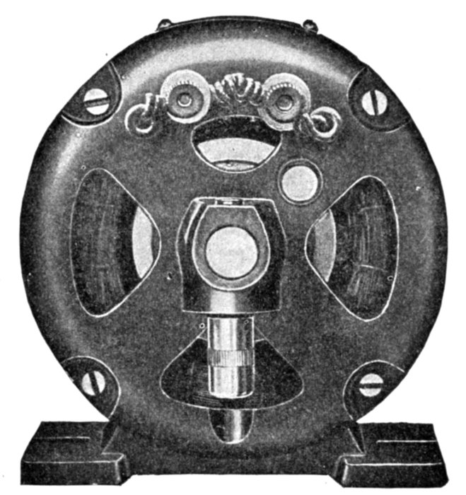
Fig. 1,858.—Switch end view of General Electric drawn shell type fractional horse power
single phase motor.
Ques. Describe one method of splitting the phase.
Ans. The field of the motor is provided, in addition to the
main single phase winding, with an auxiliary single phase winding,
and the two windings are connected in parallel to the single
phase supply mains with a resistance or a condenser placed in
series with the single phase winding, as shown in diagram
fig. 1,830, the two windings being displaced from each other[Pg 1345]
on the armature about 90 magnetic degrees, just as in the
ordinary two phase motor.
Ques. What is the construction of the two windings?
Ans. The main coils are of more turns than the auxiliary,
being spread over more surface, and are heavier because they
are for constant use; whereas the auxiliary coils are used only
while starting.
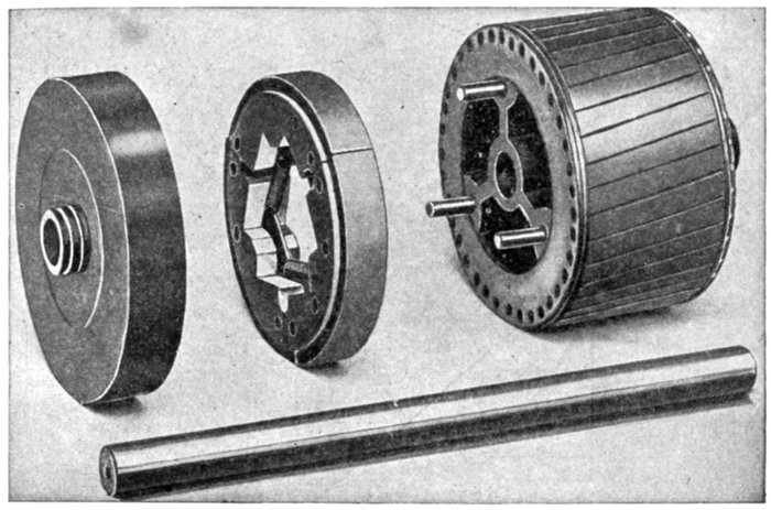
Figs. 1,859 to 1,862.—Detail construction of clutch parts of General Electric drawn shell type
fractional horse power single phase motor. The starting switch, which is assembled within
the motor frame, consists essentially of three parts: a rotating member mounted on the
armature and provided with two spring controlled pivoted levers in contact with an
insulated collector ring.
Ques. What are the auxiliary coils sometimes called?
Ans. Starting coils.
Ques. What are "shading" coils?
Ans. Auxiliary coils as placed on fan motors in the manner
shown in fig. 1,863.
[Pg 1346]
Ques. How can single phase motors be started without
the use of external phase splitting devices?
Ans. Such apparatus may be avoided by having the auxiliary
winding of larger self-inductance than the main winding.
Ques. What is the character of the starting torque
produced by splitting the phase?
Ans. It does not give strong starting torque.
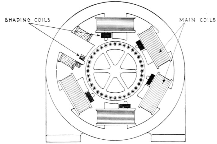
Fig. 1,863.—Single phase fan motor with shading coils for starting. In addition to the main
field coils, one tip of each pole piece is surrounded by a short circuited coil of wire or
frame of copper, as indicated in the figure. This coil, or copper frame, is called a shading
coil and it causes a phase difference between the pulsating flux that emanates from the
main portion of each polar projection and the pulsating flux which emanates from the
pole tip, thus introducing a two phase action on the armature which is sufficiently pronounced
to start the motor.
Ques. How is the plain squirrel cage armature modified
to enable the motor to start with a heavier load?
Ans. An automatic clutch is provided which allows the
armature to turn free on the shaft until it accelerates almost to
running speed.
[Pg 1347]
This type motor is known as the clutch type of single phase induction
motor. In operation when the circuit is closed, the armature starts to
revolve upon the shaft; when it reaches a premeditated speed, a
centrifugal clutch expands and engages the clutch disc, which is fastened
to the shaft.
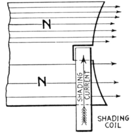
Fig. 1,864.—Diagram showing action of shading coil in alternating current motor. The
extremities of these pole pieces are divided into two branches, one of which a copper ring
called a shading coil is placed as shown, while the other is left unshaded. The action of
the shading coils is as follows: Consider the field poles to be energized by single phase
current, and assume the current to be flowing in a direction to make a north pole at the
top. Consider the poles to be just at the point of forming. Lines of force will tend to
pass downward through the shading coil and the remainder of the pole. Any change of
lines within the shading coil generates an e.m.f., which causes to flow through the coil a
current of a value depending on the e.m.f. and always in a direction to oppose the change
of lines. The field flux is, therefore, partly shifted to the free portion of the pole, while
the accumulation of lines through the shading coil is retarded.
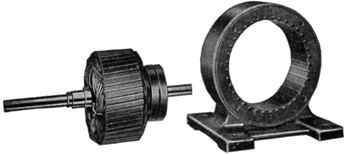
Figs. 1,865 and 1,866.—Fort Wayne split phase factional horse power induction motor with
stationary armature. The object of placing the squirrel cage armature winding on the
stationary part or frame is to decrease the radial depth of the latter more than would be
possible with the usual arrangement where the armature forms the rotating part. The
small radial depth of the stationary armature makes possible a revolving field of maximum
diameter giving in turn an exceptionally large air gap area, which reduces the magnetizing
current, hence improves the power factor of the motor.
[Pg 1348]
Ques. Explain in detail the action of the clutch type of
motor in starting.
Ans. It can start a load which requires much more than full
load torque at starting, because the motor being nearly up to
full speed, has available not only its maximum overload capacity,
but also the momentum of the armature to overcome the inertia
of the driven apparatus. In this it is assisted by a certain amount
of slippage in the clutch, which is the case when the armature
speed is pulled down to such a point as to reduce the grip of the
centrifugal clutch.
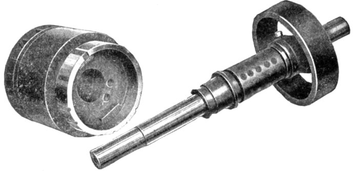
Figs. 1,867 and 1,868.—General Electric disassembled clutch as used on clutch type, single phase
(KS) induction motor. In starting, the armature revolves freely on the shaft until approximately
75 per cent. of normal rated speed is reached. The load is then picked up by the
automatic action of a centrifugal clutch, which rigidly engages an outer shell, keyed
directly to the shaft. The brass friction band of the clutch is permanently keyed to the
pulley end of the armature.
Commutator Motors.—Machines of this class are similar
in general construction to direct current motors. They have a
closed coil winding, which is connected to a commutator.
There are several types of commutator motor, namely:
- 1. Series;
- 2. Shunt;
- 3. Compensated;
- 4. Repulsion.
[Pg 1349]
Since, as stated, commutator motors are similar to direct
current motors, the question may be asked: Is it possible to run a
direct current motor with alternating current? If the mains
leading to a direct current motor be reversed, the direction or
rotation remains the same, because the currents through both
the field magnets and armature are reversed. It must follow
then that an alternating current applied to a direct current motor
would cause rotation of the armature.
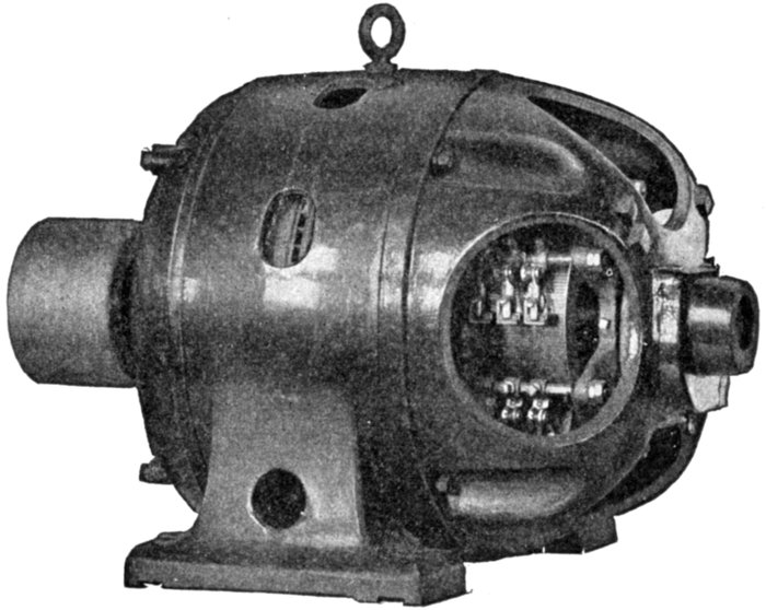
Fig. 1,869.—Wagner single phase variable speed commutator motor. The commutator is of
the regular horizontal type and the brushes remain in contact all the time. As the torque
of alternating motors varies directly as the square of the applied pressure, wide speed
variation may be obtained by varying the voltage applied at the motor terminals.
Action of Closed Coil Rotating in Alternating Field.—When
a closed coil rotates in an alternating field, there are several
different pressures set up and in order to carefully distinguish
between them, they may be called:
[Pg 1350]
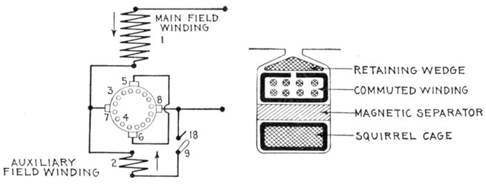
Figs. 1,870 and 1,871.—Diagrams illustrating construction and operation of Wagner "unity
power factor" single phase motor. In the field construction, fig. 1,870, two windings are
used. The main winding 1 produces the initial field magnetization as heretofore; the
auxiliary winding 2 controls the power factor or "compensates" the motor. The main
structural departure is in the armature, the construction of which is more clearly indicated
in fig. 1,871. Here again two windings are employed. The main or principal winding 4
is of the usual well known squirrel cage type and occupies the bottom of the armature slots.
The second or auxiliary winding 3 is of the usual commuted type, is connected to a standard
form of horizontal commutator and occupies the upper portion of the armature slots.
Between the two is placed a magnetic separator in the form of a rolled steel bar. Two
sets of brushes are provided, as indicated in the diagram of connections shown in fig. 1,870.
The main pair of brushes 5-6 is placed in the axis of the main field winding 1 and is
short circuited. The auxiliary pair of brushes 7-8 is placed at right angles to the axis of
the main field winding and is connected in series with it at starting. The auxiliary field
winding 2 is permanently connected to one auxiliary brush 7, and is adapted to be connected
to the other auxiliary brush 8 by means of the switch 9. The purpose of the
peculiar armature construction illustrated in fig. 1,871 and of the brush arrangement and
connections shown in fig. 1,870 is to accentuate, at starting, the effect of the squirrel cage
along the axis 5-6 of the main field winding 1, while suppressing it as far as possible along
the axis 7-8 at right angles to main winding. The magnetic separator placed above the
squirrel cage winding 4 tends to suppress the effect of that winding along all axes, by making
it less responsive to outside inductive effects. But the influence of the separator is nullified
along the axis of the main field winding by the presence of the short circuited brushes 5-6,
while no means are provided for nullifying its effects along the axis at right angles to that
of the main field winding. Thus the main field winding 1 will be able to induce heavy
currents in both armature windings because of the short circuited brushes in the axis 5-6,
and in spite of the magnetic separator; while the armature winding 3, connected in series
with 1, will not be able to produce heavy currents in the squirrel cage winding 4 along the
axis 7-8 because of the magnetic separator between 3 and 4, which shunts or side tracks the
inducing magnetic flux. In operation, at starting, switch 9 of fig. 1,870 is open, the commuted
winding 3 along the axis 7-8 being connected in series with the main field winding 1
and across the mains. The winding 1 induces a large current in the armature windings
3 and 4 along the axis 5-6, and the winding 3 produces a large flux along the axis 7-8.
The armature currents in the main axis co-acting with the flux threading the armature along
the auxiliary axis yield the greater part of the starting torque. As the motor speeds up,
the squirrel cage gradually assumes those functions which it performs in the ordinary
single phase, squirrel cage motor, developing a magnetic field of its own along the axis 7-8
and a correspondingly powerful torque, which increases very rapidly as synchronism is
approached, but falls suddenly to zero at or near actual synchronism. It is known that
the magnetizing currents circulating in the bars of the squirrel cage of a single phase motor
have, at synchronism, double the frequency of the stator currents; the fluxes they produce
must therefore also be of double frequency. Now, the magnetic separator is made of
solid steel, and, while this separator forms a sufficiently effective shunt for the fluxes of
line frequency induced from the field, it is quite ineffective as a shunt for the double frequency
fluxes produced by the armature. With respect to the squirrel cage, the effect of
this magnetic separator diminishes with increasing speed, and at synchronism the machine
operates practically in the same manner as if the magnetic separator did not exist.
[Pg 1351]
- 1. The transformer pressure;
- 2. The generated pressure;
- 3. The self-induction pressure.
These pressures may be defined as follows:
The transformer pressure is that pressure induced in the
armature by the alternating flux from the field magnets.
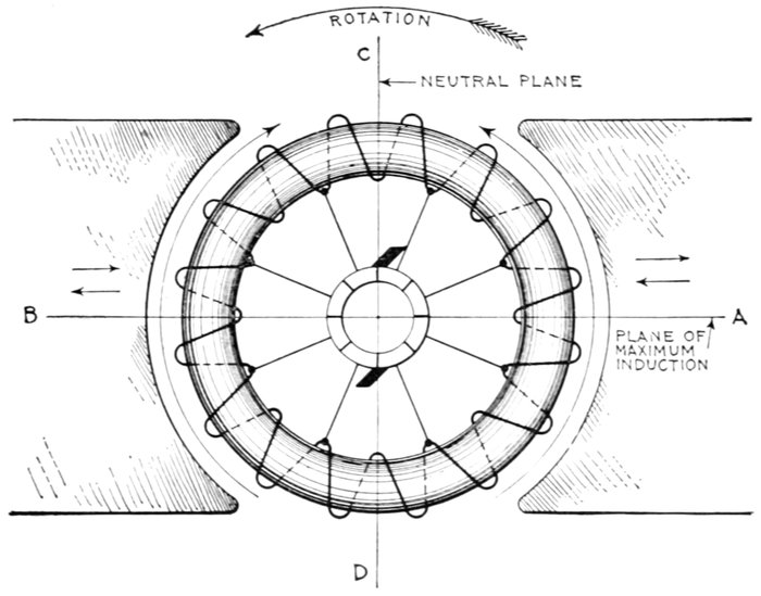
Fig. 1,872.—Diagram of ring armature in alternating field illustrating the principles of commutator
motors.
For instance, assuming in fig. 1,872 the armature to be at rest, as the
alternating current which energizes the magnets rises and falls in value,
the variations of flux which threads through the coils of the ring winding,
induce pressure in them in just the same way that pressure is induced
in the secondary of a transformer.
A ring winding is used for simplicity; the same conditions obtain
in a drum winding.
[Pg 1352]
The generated pressure is that pressure induced in the
armature by the cutting of the flux when the armature rotates.
The self-induction pressure is that pressure induced in
both the field and armature by self-induction.
Nature of the Generated Pressure.—In fig. 1,872, the generated
pressure induced by the rotation of the armature is minimum at the neutral
plane C D and maximum at A B. It tends to cause current to flow up
each half of the armature from D to C, producing poles at these points.
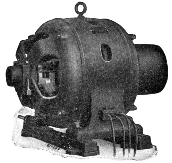
Fig. 1,873.—Wagner single phase repulsion induction commutator motor. Its working
principle is repulsion start and induction operation. Starting with the machine at rest,
brushes in pairs cross connected through a low resistance conductor, bear upon the
commutator, temporarily short circuiting the armature winding then developing a strong
starting torque on the repulsion principle. On attaining full load speed the individual
segments of the commutator are all positively connected together by the operation of an
automatic centrifugal governor, thereby transforming the armature winding to the
squirrel cage form, the motor then continuing as an induction motor. The governor at
the same time removes the brushes from contact with the commutator to save wear. If
the power service should fail for any reason, the motor returns to the starting condition,
and picks up its load when the power comes on again without attention of the operator.
Nature of the Transformer Pressure.—This is caused by variations
of the flux passing through each coil of the armature winding.
Evidently this variation is least at the plane A B because at this point[Pg 1353]
the coils are inclined very acutely to the flux, and greatest at the plane
C D where the coils are perpendicular to the flux. Accordingly, the
transformer pressure induced in the armature winding is least at A B
and greatest at C D.
The transformer pressure acts in the same direction as the generated
pressure as indicated by the long arrows and gives rise to what may be
called local armature currents.
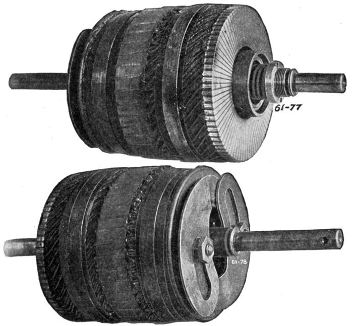
Figs. 1,874 and 1,875.—Armature of Wagner single phase repulsion-induction commutator
motor as seen from the commutator and rear ends, showing the vertical commutator and
type of governor employed on the smaller sizes. The operation is explained in fig. 1,873.
Nature of the Self-induction Pressure.—The self-induction
pressure, being opposite in direction to the impressed pressure, it must
be evident that in the operation of an alternating current commutator
motor, the impressed pressure must overcome not only the generated
[Pg 1354]
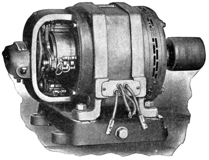
Fig. 1,876.—General Electric single phase compensated repulsion motor. The frame is of
the riveted form and the field winding consists of distributed concentric coils, each being
separately insulated and taped up to each core slot. The compensating winding (depending
usually on the size of frame), forms either the center portion of the main winding
or a separate winding concentric therewith. The polar groupings are arranged for a
frequency of 25 and 60. There are four terminal leads permitting interchangeability of
operation on 110 or 220 volt circuits. By connecting adjacent pairs of these terminals in
multiple, motors of this type are made adaptable for 110 volt service; for double this
pressure the four leading in wires are connected in series. The motor will operate satisfactorily
where the arithmetical sum of voltage and frequency variation does not exceed
10 per cent.; that is, the voltage may be 10 per cent. high if the frequency remain at
normal, or the frequency may be 10 per cent. high assuming no variation in voltage. A
decrease of 5 per cent. in frequency accompanied by a similar increase in voltage is permissible
or, as above stated, any similar combination whose arithmetical sum is within
10 per cent. of normal. The armature winding is of the series drum type connected to a
commutator carrying two sets of brushes, each set being displaced electrically from the other
by 90 degrees. The first set, known as the energy brushes, is permanently short circuited
and disposed at an angle to the lines of field or primary magnetization, as in an ordinary
repulsion motor. The second set, or compensating brushes, is connected to a small portion
of the primary winding included in the field circuit, so as to impress upon the armature
an electromotive force, which serves both to raise the power factor and at the same time
maintain approximately synchronous speed at all loads. The armature laminations are
built up on a cast iron sleeve having the same inside bore as the commutator. In case
the shaft become damaged or worn, it can be readily pressed out and replaced without
disturbing the commutator or windings. The motor is connected to run counter clockwise.
Clockwise rotation is obtained by interchanging the leads to the compensating
brushes and slightly shifting the brush holder yoke. This type motor may be thrown on
the line without the use of a rheostat, and is suitable for operating refrigerating machines,
air compressors, house pumps or similar apparatus where a float switch or pressure regulator
is used to close or open the supply circuit.
[Pg 1355]
pressure but also the self-induction pressure. Hence, as compared to
an equivalent direct current motor, the applied voltage must be greater
than in the direct current machine, to produce an equal current.

Fig. 1,877.—Armature of General Electric single phase compensated repulsion motor,
assembled ready for dip and banding.
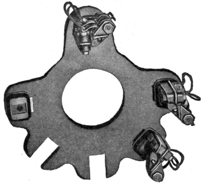
Fig. 1,878.—Cast brush rigging of General Electric single phase compensated repulsion motor
as used for the 3 and 5 horse power motors.
The Local Armature Currents.—These currents produced by
the transformer pressure occur in those coils undergoing commutation.
They are large, because the maximum transformer action
occurs in them, that is, in the coils short circuited by the brushes.
[Pg 1356]
Ques. Why do the local armature currents cause
sparking?
Ans. Because of the sudden interruption of the large volume
of current, and also because the flux set up by the local currents
being in opposition to the field flux, tends to weaken the field
just when and where its greatest strength is required for commutation.

Fig. 1,879.—Field of Sprague single phase compensated repulsion motor. The frame is of the
skeleton form which exposes the core, giving effective heat radiation. The single phase
field winding is of the distributed concentric type. To facilitate connection to circuits of
either 110 or 220 volts, four plainly tagged leads are brought out to the back of the removable
terminal board.
Ques. What is the strength of the local current?
Ans. They may be from 5 to 15 times the strength of the
normal armature current.
Ques. Upon what does the local armature current
depend?
Ans. Upon the number of turns of the short circuited coils,
their resistance, and the frequency.
[Pg 1357]
Ques. How can the local currents be reduced to avoid
heavy sparking?
Ans. 1. By reducing the number of turns of the short
circuited coils, that is, providing a greater number of commutator
bars; 2, reducing the frequency; and 3, increasing the
resistance of the short circuited coil circuit: a, by means of high resistance
connectors; or b, by using brushes of higher resistance.
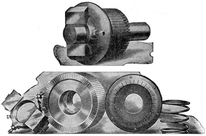
Figs. 1,880 to 1,884.—Assembly and disassembled view of short circuiting device as used on
Bell single phase repulsion induction motor. The armature, which is wound in a similar
manner to those used in direct current motors, has a commutator, and brushes, which
being short circuited on themselves, allow great starting torque, with small starting
current. The motor starts by the repulsion principle, and on reaching nearly full speed,
a centrifugal governor pushes the copper ring against the commutator segments, thereby
short circuiting them, and the motor then operates on the induction principle.
Ques. What are high resistance connectors?
Ans. The connectors between the armature winding and the
commutator bars, as shown in fig. 1,885.
[Pg 1358]
Ques. Does the added resistance of preventive leads, or
high resistance brushes, materially reduce the efficiency of
the machine?
Ans. Not to any great extent, because it is very small in
comparison with the resistance of the whole armature winding.
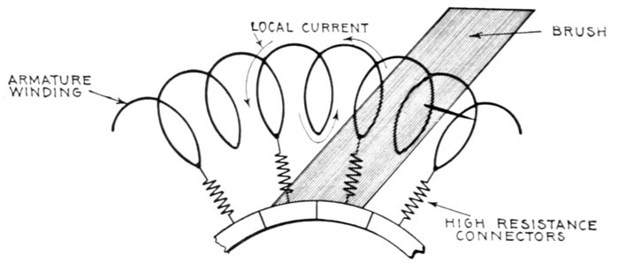
Fig. 1,885.—Section of ring armature of commutator motor showing local current set up by
transformer action of the alternating flux.
Ques. What is the objection to reducing the number of
turns of the short circuited coils to diminish the tendency
to sparking?
Ans. The cost of the additional number of commutator
bars and connectors as well as the added mechanism.
Ques. What effect has the inductance of the field and
armature on the power factor?
Ans. It produces phase difference between the current and
impressed pressure resulting in a low power factor.
Ques. What is the effect of this low power factor?
Ans. The regulation and efficiency of the system is impaired.
The frequency, the field flux and the number of turns in the winding
have influence on the power factor.
[Pg 1359]
Ques. How does the frequency affect the power factor?
Ans. Lowering the frequency tends to improve the power
factor.
The use of very low frequencies has the disadvantage of departing
from standard frequencies, and the probability that the greater cost of
transformers and alternators would offset the gain.
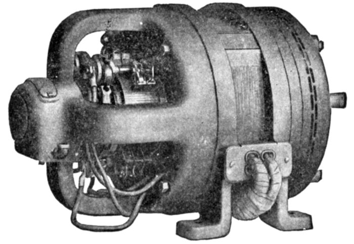
Fig. 1,886.—General Electric 5 H.P., 6 pole adjustable speed single phase compensated
repulsion motor. This type is suitable for service requirements demanding the use of a
motor whose speed can be adjusted over a considerable range, this speed at a fixed controller
setting remaining practically unaffected by any load within the motor's rated
capacity. With the controller on the high speed points, the motor possesses an inherent
speed regulation between no load and full load of approximately 6 per cent. At the low
speed points, under similar load conditions, the speed variation will be approximately 20
per cent. To secure adjustable speed control, the armature circuits employ transformers,
whose primaries are excited by the line circuit. The secondaries of these transformers
are divided into two sections; the first or "regulating" circuit is placed across the energy
brushes; the other section, since it is connected in series with the compensating winding,
maintains the high power factor and speed regulation obtained in the constant speed
type. The speed range is 2:1, approximately one-half of this range being below and
one-half above synchronous speed.
Series Motors.—This class of commutator motor is about
the simplest of the several types belonging to this division. In
general design the series motor is identical with the series direct
current motor, but all the iron of the magnetic circuit must be
laminated and a neutralizing winding is often employed.
It will be readily understood that the torque is produced in
the same way as in the direct current machine, when it is[Pg 1360]
remembered that the direction of rotation of the direct current
series motor is independent of the direction of the voltage applied.
At any moment the torque will be proportional to the product
of the current and the flux which it is at that moment producing
in the magnetic system, and the average torque will be the product
of the average current and the average flux it produces, so that
if the iron parts be unsaturated, as they must be if the iron losses
are not to be too high, the torque will be proportional simply to
the square of the current, there being no question of power factor
entering into the consideration.
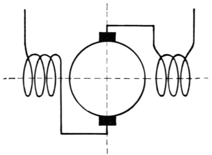
Fig. 1,887.—Diagram of single phase series commutator motor. It is practically the same
as the series direct current motor, with the exception that all the metal of the magnetic
circuit must be laminated.
Ques. What are the characteristics of the series motor?
Ans. They are similar to the direct current series motor,
the torque being a maximum at starting and decreasing as the
speed increases.
Ques. For what service is the series motor especially
suited?
Ans. On account of its powerful starting torque it is particularly
desirable for traction service.
[Pg 1361]
Neutralized Series Motor.—A chief defect of the series
motor is the excessive self-induction of the armature, hence in
almost every modern single phase series motor a neutralizing
coil is employed to diminish the armature self-induction.
The neutralizing coil is wound upon the frame 90 magnetic
degrees or half a pole pitch from the field winding and arranged
to carry a current equal in magnetic pressure and opposite in
phase to the current in the armature.

Fig. 1,888.—Diagram of neutralized series motor; conductive method. In the simple series
motor, there will be a distortion of the flux as in the direct current motor. As the distorting
magnetic pressure is in phase with that of the magnets, the distortion of the flux
will be a fixed effect. If the poles be definite as in direct current machines, this distortion
may not seriously affect the running of the motor, but with a magnetizing system like
that universally adopted in induction motors the flux will be shifted as a whole in the
direction of the distortion, which will produce the same effect as if in the former case
the brushes had been shifted forward, whereas for good commutation they should have
been shifted backward. As in direct current machines, this distortion is undesirable
since it is not conducive to sparkless working, and also reduces to a more or less extent
the torque exerted by the motor. The simplest remedy is to provide neutralizing coils
displaced 90 magnetic degrees to the main field coils as shown. The neutralizing current
is obtained by the method of connecting the neutralizing coils in series in the main circuit.
The current through the neutralizing winding may be obtained,
either
- 1. Conductively; or
- 2. Inductively.
[Pg 1362]
In the conductive method, fig. 1,888, the winding is connected in
series as shown.
In the inductive method, fig. 1,889, the winding is short circuited
upon itself and the current obtained inductively, the neutralizing
winding being virtually the secondary of a transformer, of which the
armature is the primary.
Ques. When is the conductive method to be preferred?
Ans. When the motor is to be used on mixed circuits.
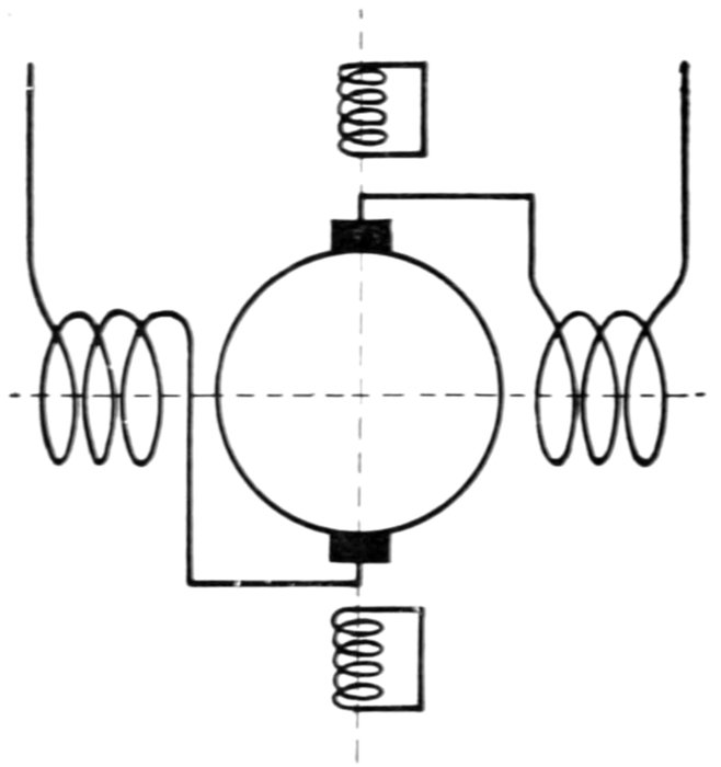
Fig. 1,889.—Diagram of neutralized series motor; inductive method. Although the conductive
method of neutralization is employed in nearly all machines, it is possible merely
to short circuit the neutralizing winding upon itself, instead of connecting it in series with
the armature circuit. In this case the flux due to the armature circuit cannot be eliminated
altogether, as sufficient flux must always remain to produce enough pressure to balance
that due to the residual impedance of the neutralizing coil. It would be a mistake to infer,
however, that on this account this method of neutralization is less effective than the conductive
one, since the residual flux simply serves to transfer to the armature circuit a drop
in pressure precisely equivalent to that due to the resistance and local self-induction of
the neutralizing coil in the conductive method.
Shunt Motors.—The simple shunt motor has inherently
many properties which render it unsuitable for practical use,
and accordingly is of little importance. Owing to the many
turns of the field winding there is large inductance in the shunt
field circuit.
[Pg 1363]
Fig. 1,890.—Diagram of simple shunt commutator motor. Owing to its many inherent
defects it is of little importance.
Fig. 1,891.—Compensated shunt induction single phase motor. The transformer shown in
the arrangement is capable of being replaced by a coil placed on the frame having the same
axis as the field winding, so that the flux produced by the field winding induces in the
coil a pressure in phase with the supply pressure. Such a coil will now be at right angles
to the circuit to which it is connected. In a similar manner a coil at right angles to the
armature circuit, that is, the circuit parallel to the stator axis, if connected in series with
that circuit, will also serve to compensate the motor.
[Pg 1364]
The inductance of the armature is small as compared with
that of the field; accordingly, the two currents differ considerably
in phase.
The phase difference between the field and armature currents
and the corresponding relation between the respective fluxes
results in a weak torque.
Fig. 1,892.—Fynn's shunt conductive single phase motor. In order to supply along the
stator axis a constant field, suitable for producing the cross flux to which the torque is due
by its action on the circuit perpendicular to the stator axis, the "armature circuit," as it
may be called, has a neutralizing coil in series with it, so that the armature circuit and
neutralizing coil together produce no flux. In addition to this, there is a magnetizing
coil along the same axis, which is connected across the mains and so produces the same
flux as the primary coil in a shunt induction machine. Fynn has proposed a number of
methods of varying the speed and compensating this machine. It is, however, complicated
in itself, and is only suited for very low voltages, so that on ordinary circuits it would
need a separate transformer.
It is necessary to use laminated construction in the field circuit
to avoid eddy currents, which otherwise would be excessive.
Fig. 1,890 is a diagram of a simple shunt commutator motor.
Repulsion Motors.—In the course of his observations on
the effects of alternating currents, in 1886-7, Elihu Thomson observed
that a copper ring placed in an alternating magnetic field
tends either to move out of the field, that is, it is repelled by the[Pg 1365]
field (hence the name repulsion motor), or to return so as to set
itself edgeways to the magnetic lines.
The explanation of the repulsion phenomenon is as follows:
When a closed coil is suspended in an alternating field so that
lines of force pass through it, as in fig. 1,893, an alternating pressure
will be induced in the coil which will be 90° later in phase
than the inducing flux, and since every coil contains some inductance
the resulting current will lag more or less with respect
to the pressure induced in the coil.

Fig. 1,893.—Effect of alternating field on copper ring. If a copper ring be suspended in an
alternating field so that the plane of the ring is oblique to the lines of force, it will turn until
its plane is parallel to the lines of force, that is, to the position in which it does not encircle
any lines of force. The turning moment acting upon the ring is proportional to the current
in it, to the strength of the field, and to the cosine of the angle ß. Hence it is proportional
to the product sin ß cos ß. The tendency to turn is zero both at 0° and at 90°; in the
former case because there is no current, in the latter because the current has no leverage.
It is a maximum when ß = 45°. Even in this position there would be no torque if there
were no lag of the currents in the ring, for the phase of the induced pressure is in quadrature
with the phase state of the field. When the field is of maximum strength there is no
pressure, and when the pressure reaches its maximum there is no field. If there be self-induction
in the ring causing the current to lag, there will be a net turning moment tending
to diminish ß. The largest torque will be obtained when the lag of the current in
the ring is 45°.
The cosine of this phase relation becomes a negative quantity
which means that the coil is repelled by the field.
It is only when the ring is in an oblique position that it tends to
turn. If it be placed with its plane directly at right angles to the[Pg 1366]
direction of the magnetic lines, it will not turn; if ever so little
displaced to the right or left, it will turn until its plane is parallel
to the lines.
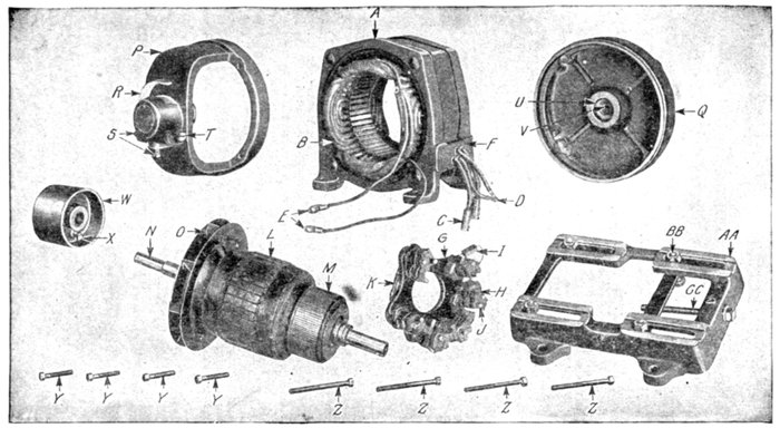
Figs. 1,894 to 1,908.—Parts of General Electric single phase compensated repulsion motor. The field frame employs the riveted
form of construction, so that the ends of the laminations are exposed directly to the air, insuring low operating temperatures
and high overload capacity. The field winding consists of a main winding of the distributed concentric type and a compensating
winding. The series type of winding is employed, and the completed rotor is treated with a special insulating compound,
which renders the coils moisture proof under ordinary conditions. On motors of more than 2 horse power capacity a ventilating
fan is attached to the rotor which provides a continuous supply of cool air while the motor is in operation. Two types of
brush holder yoke are used. The smaller motors use a moulded yoke of insulting compound, reinforced by a cast iron L
section ring embedded in the moulded structure. Cast iron yokes are used on larger motors. The brushes are of carbon
with copper pigtails, which carry all the current. The brushes in this machine remain permanently in contact with the commutator.
The parts are: A, field; B, field winding; C, line terminal; D, tube terminal; E, compensating terminal; F, terminal
board; G, brush yoke; H, brush holder; I, carbon brush; J, brush stud; K, short circuit connection; L, armature;
M, commutator, N, shaft; O, fan; P, commutator end shield; Q, pulley end shield; R, oil well cover; S, oil plugs; T, oil gauge;
U, bearing lining; V, oil ring; W, pulley; X, pulley set screw; Y, commutator end shield holding bolts; Z, pulley end
shield holding bolts; AA, base; BB, float bolts; CC, belt tightener screw.
[Pg 1367]
The production of torque may be explained by saying that the
current induced in the ring produces a cross field which being
out of phase with, and inclined to the field impressed by the
primary alternating current, causes a rotary field, and this in
turn, reacting on the conductor, a turning moment results.
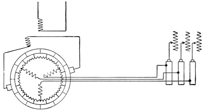
Fig. 1,909.—Fynn's compensated shunt induction motor. This is a combination of the compensated
shunt induction motor with the ordinary squirrel cage form. In one form, in
addition to the ordinary drum winding on the armature, there is another three phase
winding into the "star," of which the drum winding is connected. This second winding
is connected to three slip rings which are short circuited when the machine is up to speed.
Upon the commutator are placed a pair of brushes connected to an auxiliary winding
placed on the frame in such a position that the flux from the primary coil induces in it
a pressure of suitable phase to produce compensation. The same pair of brushes is also
used for starting.
Elihu Thompson took an ordinary direct current armature, placed it
in an alternating field, and having short circuited the brushes, placed
them in an oblique position with respect to the direction of the field.
The effect was to cause the armature to rotate with a considerable torque.
The inductors of the armature acted just as an obliquely placed ring,
but with this difference, that the obliquity was continuously preserved[Pg 1368]
by the brushes and commutator, notwithstanding that the armature
turned, and thus the rotation was continuous. This tendency of a
conductor to turn from an oblique position was thus utilized by him to
get over the difficulty of starting a single phase motor. With this object
in view he then constructed motors in which the use of commutator and
brushes was restricted to the work of merely starting the armature,
which when so started was then entirely short circuited on itself, though
disconnected from the rest of the circuit, the operation then being solely
on the induction principle.
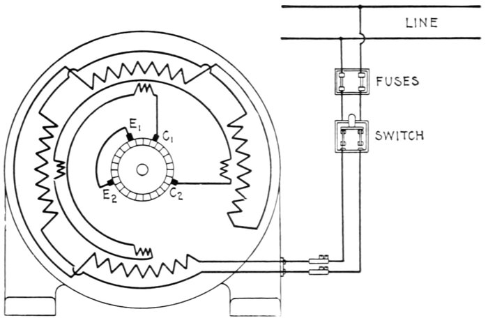
Fig. 1,910.—Diagram of connection of Sprague single phase compensated repulsion motor.
To reverse direction of rotation interchange leads C1 and C2 and slightly shift the brush
holder yoke. Brushes E1 and E2 are permanently short circuited. This diagram of connections
applies also to fig. 1,911.
Ques. What difficulty was experienced with Thomson's
motor?
Ans. Since an open coil armature was used, the torque
developed was due to only one coil at a time, which involved a
necessarily high current in the short circuited coil resulting in
heavy sparking.
[Pg 1369]
Ques. How was this remedied?
Ans. By the use of closed coil armatures in later construction.
Ques. Did this effectually stop sparking?
Ans. No.
Ques. What other means is employed in modern designs
to reduce sparking?
Ans. Compensation and the use of a distributed field winding,
high resistance connectors, high resistance brushes, etc.
Ques. What are the names of the two classes of repulsion
motor?
Ans. The simple and the compensated types.
Ques. Describe a simple repulsion motor.
Ans. It consists essentially of an armature, commutator and
field magnets. The armature is wound exactly like a direct
current armature, and the windings are connected to a commutator.
The carbon brushes which rest on this commutator
are not connected to the outside line, however, but are all connected
together through heavy short circuiting connectors.
The brushes are placed about 60° or 70° from the neutral axis.
The field is wound exactly like that of the usual induction motor.
Ques. What is the action of this type of motor?
Ans. If nothing be done to prevent, the motor will increase
in speed at no load until the armature bursts, just as it will in a
series direct current motor.
Ques. What provision is made to avoid this danger?
Ans. A governor is usually mounted on the armature which
short circuits the windings, after the motor has been started.
The motor then runs as a squirrel cage induction motor. As a[Pg 1370]
rule the brushes are lifted off the commutator when the armature
is short circuited, so as to prolong their life.
This is a very successful motor, but it is of course more costly than
the simple squirrel cage motor used on two and three-phase circuits.

Fig. 1,911.—Diagram of connections of Sprague variable speed single phase compensated
repulsion motor and controller. The controller is designed to give speed reduction and
speed increase as resistance or reactance is inserted in the energy and compensating
circuits. With the exception of the leads brought out from these circuits, the constant
speed and variable speed motors are identical. The standard controller gives approximately
2:1 speed variation.
Ques. What name may appropriately be applied to the
motor?
Ans. It may be called the repulsion induction motor, because
it is constructed for repulsion start and induction running.
Ques. Describe a compensated repulsion motor.
Ans. In its simplest form it consists of a simple repulsion
motor in which there are two independent sets of brushes, one[Pg 1371]
set being short circuited, while the other set is in series with the
field magnet winding, as in the series alternating current motor.
Ques. What names are given to the two sets of
brushes on a compensated repulsion motor?
Ans. The energy or main short circuiting brushes, and the
compensating brushes.
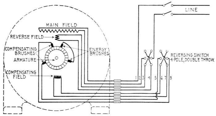
Fig. 1,912.—Diagram of connections of Sprague reversing type of single phase compensated
repulsion motor. As shown, there is a special reverse field winding having terminals for
connection to a four pole double throw switch.
Ques. What is the behavior of the armature of a
compensated repulsion motor at starting?
Ans. It possesses at starting most of the apparent reactance
of the motor, and the effect of speed is to decrease such apparent
reactance, the latter becoming zero at either positive or
negative synchronism, and negative at higher speeds in either
direction.
[Pg 1372]
Ques. What is the nature of the field circuit of the
compensated repulsion motor at starting?
Ans. At starting it is practically non-inductive, the effect
of speed being to introduce a spurious resistance which increases
directly with the speed, and becomes negative when
the speed is reversed.
Ques. For what use is the compensated repulsion
motor especially adapted?
Ans. For light railroad service.
Ques. When employed thus what is the method of
control?
Ans. A series transformer is used in the field circuit.
Ques. What frequencies are employed with this
motor?
Ans. 25 to 60, the preferred frequency being 40.
Ques. To what important use is the repulsion principle
put?
Ans. It is sometimes employed for starting on single phase
induction motors.
In this method, after bringing the motor up to speed, the winding is
then short circuited upon itself, and the motor then operates on the
induction principle.
Ques. What name is given to this type of motor?
Ans. It is called the repulsion induction motor.
[Pg 1373]
Power Factor of Induction Motors.—In the case of a
direct current motor, the energy supplied is found by multiplying
the current strength by the voltage, but in all induction motors
the effect of self-induction causes the current to lag behind the
pressure, thereby increasing the amount of current taken by
the motor. Accordingly, as the increased current is not utilized by
the motor in developing power, the value obtained by multiplying
the current by the voltage represents an apparent energy
which is greater than the real energy supplied to the motor.
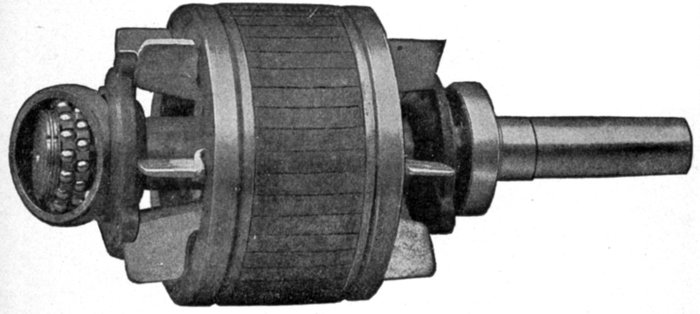
Fig. 1,913.—Fairbanks-Morse squirrel cage armature, showing ball bearings.
It is evident, that if it were possible to eliminate the lag entirely,
the real and apparent watts would be equal, and the
power factor would be unity.
The importance of power factor and its effect upon both
alternator capacity and voltage regulation is deserving of the
most careful consideration with all electrical apparatus, in which
an inherent phase difference exists between the pressure and the
current, as for instance in static transformers and induction motors.
[Pg 1374]
While the belief is current that any decrease in power factor
from unity value does not demand any increase of mechanical
output, this is not true, since all internal alternator and line
losses manifest themselves as heat, the wasted energy to
produce this heat being supplied by the prime mover.
Apart from the poor voltage regulation of alternating current
generators requiring abnormal field excitation to compensate for
low power factor, some of the station's rated output is rendered
unavailable and consequently produces no revenue. The poor
steam economy of underloaded engines is also a serious source
of fuel wastage.
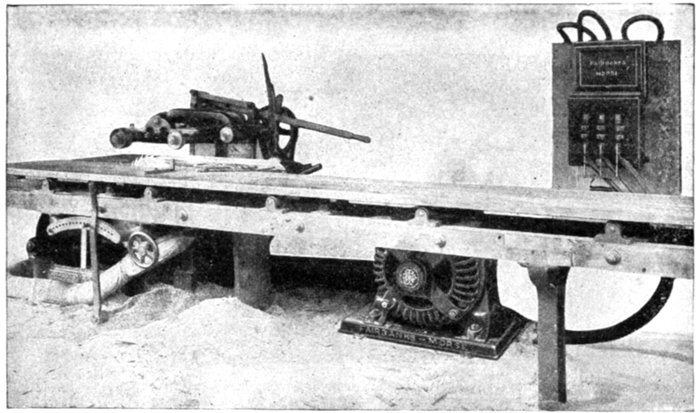
Fig. 1,914.—Fairbanks-Morse 20 horse power squirrel cage induction motor connected to a
20 inch self-feed rip and chamfering saw. The absence of commutator and brushes on
the squirrel cage armature eliminates sparking and therefore renders this type of motor
particularly adapted for use in places where sparking would be dangerous, such as in
wood working plants, textile mills, etc.
Careful investigations have shown that the power factor of industrial
plants using induction motor drive with units of various sizes will average
between 60 and 80 per cent. With plants supplying current to underloaded
motors having inherently high lagging current values, a[Pg 1375]
combined factor as low as 50 per cent. may be expected. Since standard
alternators are seldom designed to carry their rated kilowatt load at less
than 80 per cent. power factor, the net available output is, therefore,
considerably increased.
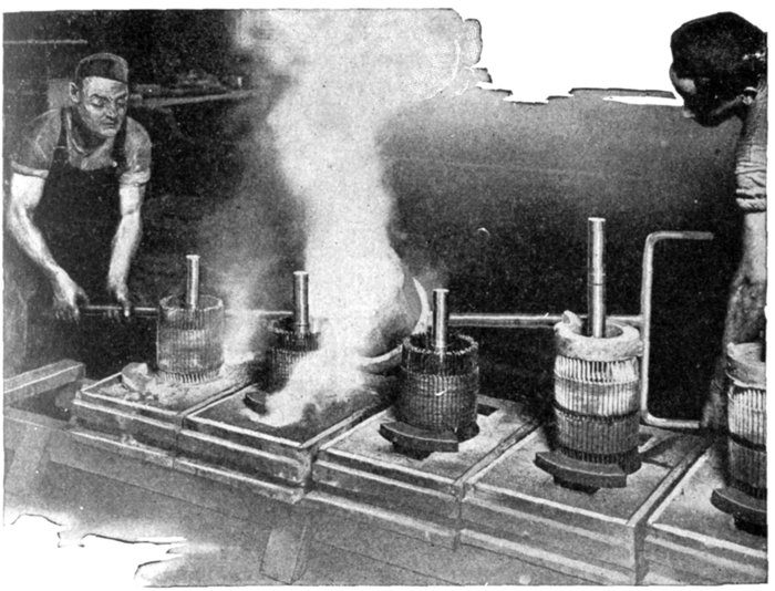
Fig. 1,915.—Method of casting end rings on squirrel cage armatures of Fairbanks-Morse induction
motors. The metal being fused to the bars at a temperature in excess of 1,832
degrees Fahr., it is readily seen that the destructive effect of any subsequent heating is
eliminated. While giving the most intimate contact at the joints, a multiplicity of joints
is avoided as well as solder.
Speed and Torque of Motors.—The speed of an induction
motor depends chiefly on the frequency of the circuit and runs
within 5 per cent. of its rated speed; it will produce full torque
if the line voltage do not vary more than 5 to 10 per cent.
At low voltage the speed will not be greatly reduced as in a
direct current motor, but as the torque is low the motor is easily
stopped when a light load is thrown on.
[Pg 1376]
The current taken by an induction motor from a constant
pressure line varies with the speed as in a direct current motor.
When a load is thrown on, the speed is reduced correspondingly
and as the self-induction or reactance is diminished, more
current circulates in the squirrel cage winding, which in turn
reacts on the field coils in a similar manner and more current
flows in them from the line. In this manner the motor automatically
takes current from the line proportional to the load
and maintains a nearly constant speed.
The so-called constant speed motors require slight variations
in speed to automatically take current from the line when the
load varies.
Induction motors vary in speed from 5 to 10 per cent., while
synchronous motors vary but a fraction of one per cent.
Single phase motors to render efficient service must be able,
where requisite, to develop sufficient turning moment or torque
to accelerate, from standstill, loads possessing large inertia or
excessive static friction; for example, meat choppers and grinders,
sugar or laundry centrifugals; heavy punch presses; group
driven machines running from countershafts with possibly over
taut belting, poor alignment, lubrication, etc.
[Pg 1377]
CHAPTER LII
TRANSFORMERS
The developments in the field of electrical engineering which
have rendered feasible the transmission of high pressure
currents over long distances, together with the reliability and
efficiency of modern generating units, have resulted in notable
economies in the generation and distribution of electric current.
This has been accomplished largely by the use of distant
water power or the centralization of the generating plants of a
large territory in a single power station.
The transformer is one of the essential factors in effecting the
economical distribution of electric energy, and may be defined as
an apparatus used for changing the voltage and current of an
alternating circuit. A transformer consists essentially of:
- 1. A primary winding;
- 2. A secondary winding;
- 3. An iron core.
Basic Principles.—If a current be passed through a coil of
wire encircling a bar of soft iron the iron will become a magnet;
when the current is discontinued the bar loses its magnetization.
Conversely: If a bar of iron carrying a coil of wire be magnetized
in a direction at right angles to the plane of the coil a
momentary electric pressure will be induced in the wire; if the
current be reversed, another momentary pressure will be induced
in the opposite direction in the coil.
[Pg 1378]
These actions are fully explained in chaps. X and XI, and as
they are perfectly familiar phenomena, a detailed explanation
of the principles upon which they depend is not necessary here.
From the first two statements given above it is evident that if a bar
of iron be provided with two coils of wire, one of which is supplied from a
source of alternating current, as shown diagrammatically by fig. 1,916,
at each impulse of the exciting current a pressure will be induced in the
secondary coil, the direction of these impulses alternating like that of
the exciting current.
Ques. What name is given to the coil through which
current from the source flows?
Ans. The primary winding.

Fig. 1,916.—Diagram of elementary transformer with non-continuous core and connection
with single phase alternator. The three essential parts are: primary winding, secondary
winding, and an iron core.
Ques. What name is given to the coil in which a
current is induced?
Ans. The secondary winding.
Similarly, the current from the source (alternator) is called the primary
current and the induced current, the secondary current.
Ques. What is the objection to the elementary transformer
shown in fig. 1,916?
Ans. The non-continuous core. With this type core, the
flux emanating from the north pole of the bar has to return to[Pg 1379]
the south pole through the surrounding air; and as the reluctance
of air is much greater than that of iron, the magnetism
will be weak.
Ques. How is this overcome?
Ans. By the use of a continuous core as shown in fig. 1,917.
Ques. Is this the best arrangement, and why?
Ans. No. If the windings were put on as in fig. 1,917, the
leakage of magnetic lines of force would be excessive, as indicated
by the dotted lines. In such a case the lines which leak through
air have no effect upon the secondary winding, and are therefore
wasted.

Fig. 1,917.—Diagram of elementary transformer with continuous core and connections with
alternator. The dotted lines show the leakage of magnetic lines. To remedy this the
arrangement shown in fig. 1,918 is used.
Ques. How is the magnetic leakage reduced to a minimum
in commercial transformers?
Ans. In these, and even in ordinary induction coils (the operating
principle of which is the same as that of transformers) the
magnetic leakage is reduced to the lowest possible amount by
arranging the coils one within the other, as shown in cross section
in fig. 1,918.
[Pg 1380]
The Induced Voltage.—The pressure induced in the
secondary winding will depend on the ratio between the number
of turns in the two windings. For example, a transformer with
500 turns of wire in its primary winding and 50 turns in its
secondary winding would have a transformation ratio of 10 to 1,
and if it were supplied with primary current at 1,000 volts, the
secondary pressure at no load would be 100 volts.
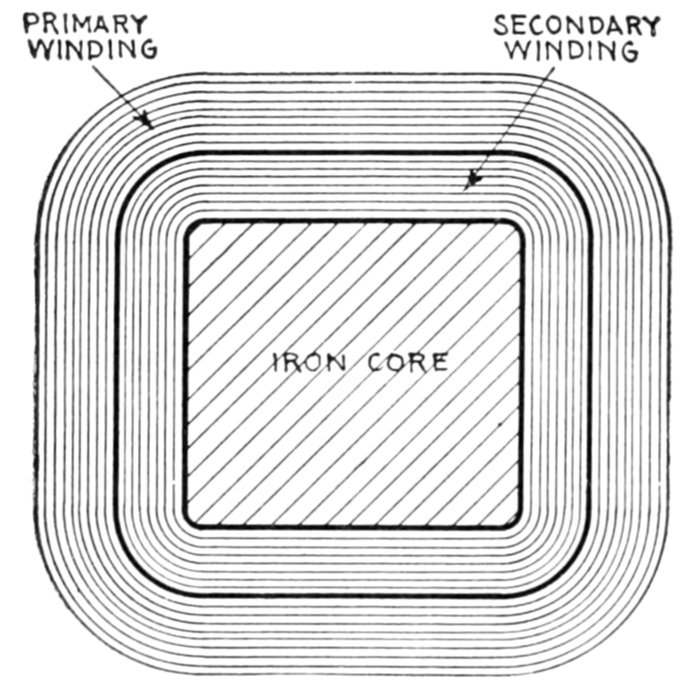
Fig. 1,918.—Cross section showing commercial arrangement of primary and secondary windings
on core. One is superposed on the other. This arrangement compels practically
all of the magnetic lines created by the primary winding to pass through the secondary
winding.
EXAMPLE.—If ten amperes flow in the primary winding and the
transformation ratio be 10, then 10 × 10 = 100 amperes will flow
through the secondary winding.
Thus, a direct proportion exists between the pressures and turns in
the two windings and an inverse proportion between the amperes and
turns, that is:
- primary voltage: secondary voltage = primary turns: secondary turns
- primary current: secondary current = secondary turns: primary turns
From the above equations it is seen that the watts of the
primary circuit equal the watts of the secondary circuit.
[Pg 1381]
Ques. Are the above relations strictly true, and why?
Ans. No, they are only approximate, because of transformer
losses.
In the above example, the total wattage in the primary circuit is
1,000 × 10 = 10 kw., and that in the secondary circuit is 100 × 100 =
10 kw. Hence, while both volts and amperes are widely different in the
two circuits, the watts for each are the same in the ideal case, that is,
assuming perfect transformer action or 100% efficiency. Now, the
usual loss in commercial transformers is about 10%, so that the actual
watts delivered in the secondary circuit is (100 × 100) × 90% = 9 kw.
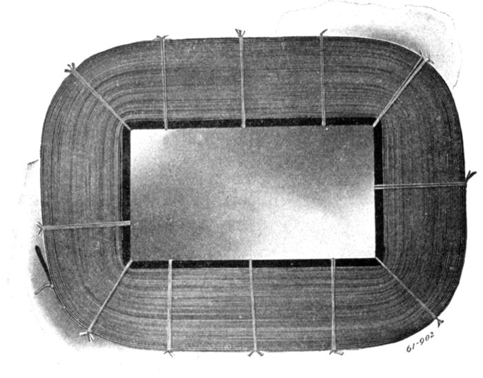
Fig. 1,919.—Wagner transformer coil formed, ready for taping. These are known as "pan
cake" coils. They are wound with flat cotton covered copper strip. In heavy coils,
several strips in parallel are used per turn in order to facilitate the winding and produce a
more compact coil.
The No Load Current.—When the secondary winding of
a transformer is open or disconnected from the secondary
circuit no current will flow in the winding, but a very small
current called the no load current will flow in the primary circuit.
[Pg 1382]
The reason for this is as follows: The current flowing in the primary
winding causes repeated reversals of magnetic flux through the iron
core. These variations of flux induce pressures in both coils; that induced
in the primary called the reverse pressure is opposite in direction
and very nearly equal to the impressed pressure, that is, to the pressure
applied to the primary winding. Accordingly the only force available to
cause current to flow through the primary winding is the difference
between the impressed pressure and reverse pressure, the effective pressure.

Fig. 1,920.—Wagner coils with insulation ready for core assembly. The flat coils, sometimes
called pancake coils are wound of flat, cotton covered, copper strip with ample insulation
between layers. In heavy coils several flat strips in multiple are used per turn in order to
facilitate the winding and produce a more compact coil. In many cases normal current
flow per high tension coil is very low and could be carried with a very small cross sectional
area of copper; however, flat strip is almost always used on account of the increased
mechanical stability thus obtained.
[Pg 1383]
The Magnetizing Current.—The magnetizing current of a
transformer is sometimes spoken of as that current which the
primary winding takes from the mains when working at normal
pressure. The true magnetizing current is only that component
of this total no load current which is in quadrature with the
supply pressure. The remaining component has to overcome
the various iron losses, and is therefore an "in phase" component.
The relation between these two components determines the
power factor of the so called "magnetizing current."
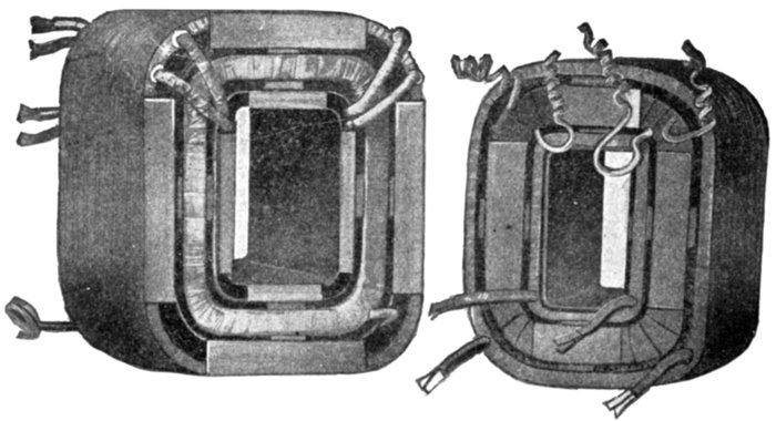
Figs. 1,921 and 1,922.—Assembled coils of Westinghouse 10 and 15 kva. transformers; views
showing ventilating ducts.
The true magnetizing component is small if the transformer
be well designed, and be worked at low flux density.
Action of Transformer with Load.—If the secondary
winding of a transformer be connected to the secondary circuit
by closing a switch so that current flows through the secondary
winding, the transformer is said to be loaded.
The action of this secondary current is to oppose the magnetizing
action of the slight current already flowing in the primary winding, thus
decreasing the maximum value reached by the alternating magnetic flux
in the core, thereby decreasing the induced pressure in each winding.
[Pg 1384]
The amount of this decrease, however, is very small, inasmuch as a
very small decrease of the induced pressure in the primary coil greatly
increases the difference between the pressure applied to the primary
coil and the opposing pressure induced in the primary coil, so that the
primary current is greatly increased. In fact, the increase of primary
current due to the loading of the transformer is just great enough (or very
nearly) to exactly balance the magnetizing action of the current in the
secondary coil; that is, the flux in the core must be maintained approximately
constant by the primary current whatever value the secondary
current may have.
When the load on a transformer is increased, the primary of the
transformer automatically takes additional current and power from
the supply mains in direct proportion to the load on the secondary.
When the load on the secondary is reduced, for example by turning
off lamps, the power taken from the supply mains by the primary coil
is automatically reduced in proportion to the decrease in the load.
This automatic action of the transformer is due to the balanced
magnetizing action of the primary and secondary currents.
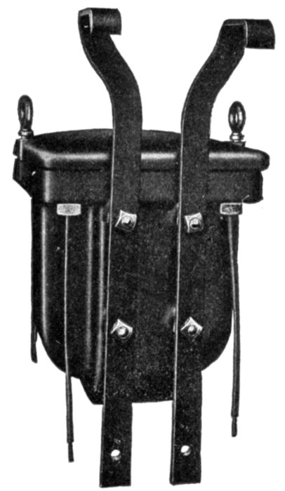
Fig. 1,923.—Rear view of Fort Wayne distributing transformer, showing hanger irons for attaching
to pole cross arm.
[Pg 1385]
Classification of Transformers.—As in the case of motors,
the great variety of transformer makes it necessary that a
classification, to be comprehensive, must be made from several
points of view, as:
1. With respect to the transformation, as
a. Step up transformers;
b. Step down transformers.
2. With respect to the arrangement of the coils and magnetic circuit, as
a. Core transformers;
b. Shell transformers;
c. Combined core and shell transformers.
3. With respect to the kind of circuit they are to be used on, as
a. Single phase transformers;
b. Polyphase transformers.
4. With respect to the method employed in cooling, as
a. Dry transformers;
b. Air cooled transformers {natural draught;
{forced draught, or air blast;
c. Oil cooled transformers;
d. Water cooled transformers.
5. With respect to the nature of their output, as
a. Constant pressure transformers;
b. Constant current transformers;
c. Current transformers;
d. Auto-transformers.
6. With respect to the kind of service, as
a. Distributing;
b. Power.
[Pg 1386]
7. With respect to the circuit connection that the transformer is constructed for, as
a. Series transformers;
b. Shunt transformers.
Step Up Transformers.—This form of transformer is used
to transform a low voltage current into a high voltage current.
Such transformers are employed at the generating end of a
transmission line to raise the voltage of the alternators to such
value as will enable the electric power to be economically transmitted
to a distant point.
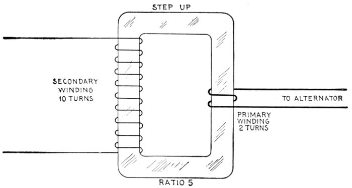
Fig. 1,924.—Diagram of elementary step up transformer. As shown the primary winding
has two turns and secondary 10 turns, giving a ratio of voltage transformation of
10 ÷ 2 = 5. Since only ⅕ as much current flows in the secondary winding as in the
primary, the latter requires heavier wire than the former.
Copper Economy with Step Up Transformers.—To comprehend
fully the bearing of the matter, it must be remembered that the energy
supplied per second is the product of two factors, the current and the
pressure at which that current is supplied; the magnitudes of the two
factors may vary, but the value of the power supplied depends only on
the product of the two; for example, the energy furnished per second
by a current of 10 amperes supplied at a pressure of 2,000 volts is[Pg 1387]
exactly the same in amount as that furnished per second by a current of
400 amperes supplied at a pressure of 50 volts; in each case, the product
is 20,000 watts.
Now the loss of energy that occurs in transmission through a well
insulated wire depends also on two factors, the current and the resistance
of the wire, and in a given wire is proportional to the square of the
current. In the above example the current of 400 amperes, if transmitted
through the same wire as the 10 amperes current, would, because it is
forty times as great, waste sixteen hundred times as much energy in
heating the wire. It follows that, for the same loss of energy, the 10
ampere current at 2,000 volts may be carried by a wire having only
1/1,600th of the sectional area of the wire used for the 400 ampere
current at 50 volts.
The cost of copper conductors for the distributing lines is therefore
very greatly economized by employing high pressures for distribution
of small currents.
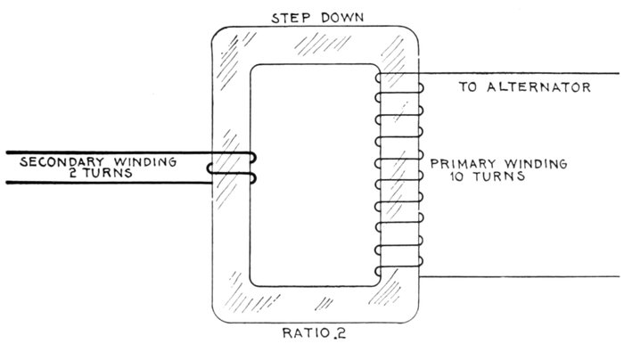
Fig. 1,925.—Diagram of elementary step down transformer. As shown the primary winding
has 10 turns and the secondary 2, giving a ratio of voltage transformation of 2 ÷ 10 = .2.
The current in the secondary being 5 times greater than in the primary will require a proportionately
heavier wire.
Step Down Transformers.—When current is supplied to
consumers for lighting purposes, and for the operation of motors,
etc., considerations of safety as well as those of suitability,[Pg 1388]
require the delivery of the current at comparatively low pressures
ranging from 100 to 250 volts for lamps, and from 100 to 600
volts for motors.
This involves that the high pressure current in the transmission
lines must be transformed to low pressure current at the
receiving or distributing points by step down transformers, an
elementary transformer being shown in fig. 1,925.
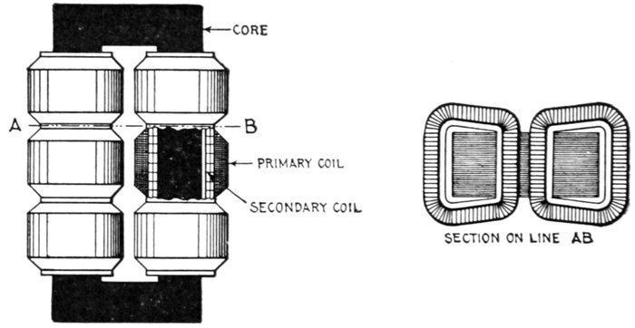
Figs. 1,926 and 1,927.—Core type transformer. It consists of a central core of laminated iron,
around which the coils are wound. A usual form of core type transformer consists of a
rectangular core, around the two long limbs of which the primary and secondary coils are
wound, the low tension coil being placed next the core.
Transformers of this type have a large number of turns in
the primary winding and a small number in the secondary, in
ratio depending on the amount of pressure reduction required.
Core Transformers.—This type of transformer may be
defined as one having an iron core, upon which the wire is
wound in such a manner that the iron is enveloped within the
coils, the outer surface of the coils being exposed to the air as
shown in figs. 1,926 and 1,927.
[Pg 1389]
Shell Transformers.—In the shell type of transformer, as
shown in fig. 1,928, the core is in the form of a shell, being built
around and through the coils. A shell transformer has, as a
rule, fewer turns and a higher voltage per turn than the core type.
Ques. What is the comparison between core and shell
transformers?
Ans. The relative advantages of the two types has been the
subject of considerable discussion among manufacturers; the
companies who formerly built only shell type transformers, now
build core types, while with other builders the opposite practice
obtains.
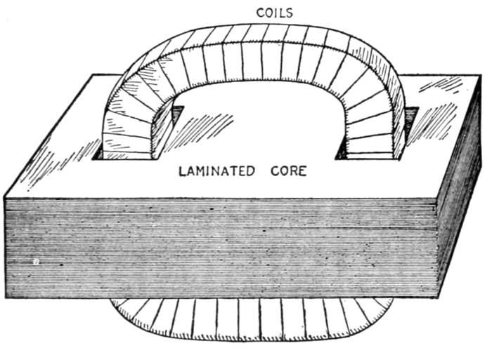
Fig. 1,928.—Shell type transformer. In construction the laminated core is built around and
through the coils as shown. For large ratings this type has some advantages with respect
to insulation, while for small ratings the core type is to be preferred in this respect. The
shell arrangement of the core gives better cooling; with this arrangement minimum
magnetic leakage is easily obtained.
Ques. Upon what does the choice between the two
types chiefly depend?
Ans. Upon manufacturing convenience rather than operating
characteristics.
[Pg 1390]
The major insulation in a core type transformer consists of several
large pieces of great mechanical strength, while in the shell type, there
are required an extremely large number of relatively small pieces of
insulating material, which necessitates careful workmanship to prevent
defects in the finished transformer, when thin or fragile material is used.
Both core and shell transformers are built for all ratings; for small
ratings the core type possesses certain advantages with reference to
insulation, while for large ratings, the shell type possesses better cooling
properties, and has less magnetic leakage than the core type.
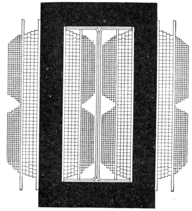
Fig. 1,929.—View illustrating the construction of cores
and coils of Maloney transformers.
Fig. 1,930.—Maloney mica
shield between primary and
secondary coils, showing
lapping feature which prevents
the wrinkling and
cracking of the mica.
Combined Core and Shell Transformers.—An improved
type of transformer has been introduced which can be considered
either as two superposed shell transformers with coils
in common, or as a single core type transformer with divided
magnetic circuit and having coils on only one leg. It is best
considered however, as a combined core and shell transformer,[Pg 1391]
and for small sizes it possesses most of the advantages of both
types. It can be constructed at less cost than can either a core
or a shell transformer having the same operating characteristics
and temperature limits.

Figs. 1,931 and 1,932.—The Berry combined core and shell transformer. It consists of a
number of inner and outer vertical and radial laminated iron blocks built up of the usual
thin sheet iron, with the coils between. The magnetic circuit is completed at the top and
bottom by other laminated blocks placed horizontally, and the whole is held together
between top and bottom cast iron frame plates by a bolt passing right down the center.
Fig. 1,931 gives a general view, W being the winding, and B, B, B, etc., the outer laminated
blocks. The construction will be better understood from fig. 1,932, where it may be supposed
that the top cap and laminated cross pieces have been removed. Here I, I, I and O, O, O
are respectively the inner and outer radial vertical blocks, P the primary, and S, S the
secondary; the latter being in two sections with the primary sandwiched between, as an
extra precaution against shock. It will be evident that this form of transformer possesses
excellent ventilation; and this is still further enhanced by opening out the winding at
intervals to leave ventilating apertures, as at A, A, A. Fig. 1,932 shows only 6 sets of radial
blocks, but the usual plan is to provide 24 or 36, according to the size of the transformer.
Fig. 1,932 shows a cross section of the first transformer of this type to
be developed commercially, and known as an "iron clad" transformer;
this construction has been used in England for some time. Fig. 1,933
shows the American practice.
[Pg 1392]

Fig. 1,933.—Plan of core of General Electric combined core and shell transformer. The core
used contains four magnetic circuits of equal reluctance, in multiple; each circuit consisting
of a separate core. In this construction one leg of each circuit is built up of two different
widths of punchings forming such a cross section that when the four circuits are
assembled together they interlock to form a central leg, upon which the winding is placed.
The four remaining legs consist of punchings of equal width. These occupy a position
surrounding the coil at equal distances from the center, on the four sides; forming a
channel between each leg and coil, thereby presenting large surfaces to the oil and allowing
its free access to all parts of the winding. The punchings of each size transformer are
all of the same length, assembled alternately, and forming two lap joints equally distributed
in the four corners of the core, thereby giving a magnetic circuit of low reluctance.
Ques. How is economy of construction obtained in
designing combined core and shell transformers?
Ans. The cross section of iron in the central leg of the core
is made somewhat less than that external to the coils, in order
to reduce the amount of copper used in the coils.
Single and Polyphase Transformers.—A single phase
transformer may be defined as one having only one set of primary
and secondary terminals, and in which the fluxes in the one or more
magnetic circuits are all in phase, as distinguished from a polyphase
transformer, or combination in one unit of several one
phase transformers with separate electric circuits but having certain
magnetic circuits in common. In polyphase transformers[Pg 1393]
there are two or more magnetic circuits through the core, and
the fluxes in the various circuits are displaced in phase.
Ques. Is it necessary to use a polyphase transformer
to transform a polyphase current?
Ans. No, a separate single phase transformer may be used
for each phase.
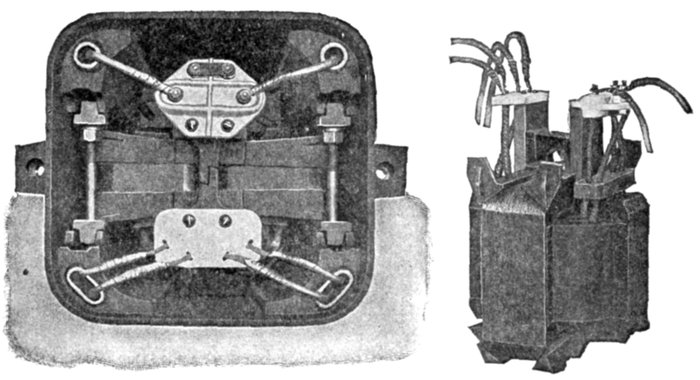
Figs. 1,934 and 1,935.—Top view showing core and coils in place, and view of coils of Westinghouse
distributing transformer. The coils are wound from round wire in the smaller
sizes of transformers and from strap copper in the larger sizes. Strap wound coils allow
a greater current carrying conductor section than coils wound from large round wire, as
there is little waste space between the different turns of the conductor. The coils are
arranged concentrically with the high tension winding between the two low tension coils,
this arrangement giving the fine regulation found in these transformers. The low tension
coils are wound in layers which extend across the whole length of the coil opening in the
iron, while the high tension coils are wound in two parts and placed end to end. This
construction reduces the normal voltage strains to a value which will not give trouble
under any condition of service. The magnetic circuit is built up of laminated, alloy steel
punchings, each layer of laminæ being reversed with reference to the preceding layer and
all joints butted. This gives a continuous magnetic circuit of low reluctance, low iron
loss and low exciting current. When assembled, the magnetic circuit consists of four
separate parallel circuits encircling the coils and protecting the windings from mechanical
injury. Separate high and low tension terminal blocks of glazed porcelain are mounted
upon extensions of the upper end frames. All danger of confusing the leads or inadvertently
making an electrical connection between the high and low tension sides of the
transformer is thus averted. The high tension winding has four leads brought to the
studs in the terminal block. Adjustable brass connectors or links between the studs
provide for series or multiple connections between two points of the high tension winding.
The position of the studs and the length of the links are so proportioned that wrong connections
on the block are impossible. Barriers on the porcelain block separate the studs
and prevent danger of arcing. Leads with means of preventing creeping of oil by capillary
action are attached to these studs and brought out of the core through porcelain bushings.
[Pg 1394]
Ques. Is there any choice between a polyphase transformer
and separate single phase transformers for transforming
a polyphase current?
Ans. Yes, the polyphase transformer is preferable, because
less iron is required than would be with the several single phase
transformers. The polyphase transformer therefore is somewhat
lighter and also more efficient.
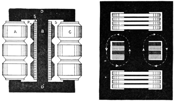
Figs. 1,936 and 1,937.—Core and shell types of three phase transformer. In the core type,
fig. 1,936, there are three cores A, B, and C, joined by the yokes D and D'. This forms a
three phase magnetic circuit, since the instantaneous sum of the fluxes is zero. Each
core is wound with a primary coil P, and a secondary coil S. As shown, the primary
winding of each phase is divided into three coils to ensure better insulation. The primaries
and secondaries may be connected star or mesh. The core B has a shorter return
path than A and C, which causes the magnetizing current in that phase to be less than in
the A and C phases. This has sometimes been obviated by placing the three cores at the
corners of an equilateral triangle (as in figs. 1,939 and 1,940), but the extra trouble involved
is not justified, as the unbalancing is a no load condition, and practically disappears when
the transformer is loaded. The shell type, fig. 1,937, consists practically of three separate
transformers in one unit. The flux paths are here separate, each pair of coils being
threaded by its own flux, which does not, as in the core type, return through the other coils.
This gives the shell type an advantage over the core type, for should one phase burn out,
the other two may still be used, especially if the faulty coils be short circuited. The effect
of such short circuiting is to prevent all but a very small flux from threading the faulty coil.
Ques. Name two varieties of polyphase transformer?
Ans. The core, and the shell types as shown in figs. 1,936
and 1,937.
[Pg 1395]
Ques. How should a three phase transformer be operated
with one phase damaged?
Ans. The damaged windings should be separated electrically
from the other coils.
The pressure winding of the damaged phase should be short circuited
upon itself and the corresponding low pressure winding should also be short
circuited upon itself. The winding
thus short circuited will choke
down the flux passing through
the portion of the core surrounded
by them without producing in
any portion of the winding a current
greater than a small fraction
of the current which would normally
exist in such portion at
full load.
Transformer Losses.—As
previously mentioned, the ratio
between the applied primary
voltage and the secondary terminal
voltage of a transformer
is not always equal to the ratio
of primary to secondary turns
of wire around the core.
The commercial transformer
is not a perfect converter of
energy, that is, the input, or
watts applied to the primary
circuit is always more than the
output or watts delivered from
the secondary winding.
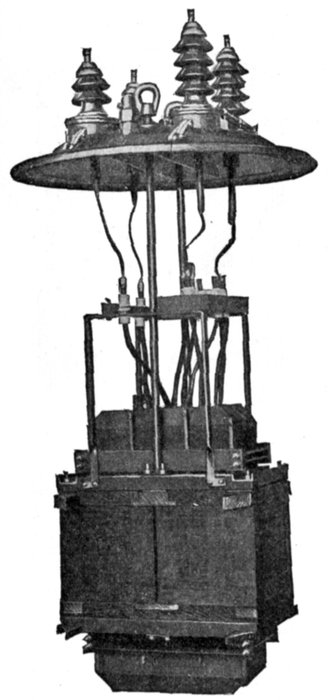
Fig. 1,938.—Interior of General Electric oil
cooled 500 kva. 33,000 volt outdoor transformer
showing lifting arrangement.
This is due to the various
losses which take place, and the[Pg 1396]
difference between the input and the output is equal to the sum
of these losses. They are divided into two classes:
- 1. The iron or core losses;
- 2. The copper losses.
The iron or core losses are due to
- 1. Hysteresis;
- 2. Eddy currents;
- 3. Magnetic leakage (negligibly small).
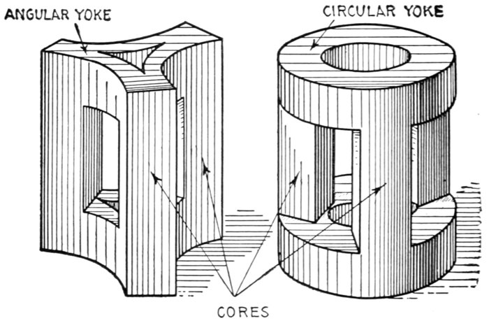
Figs. 1,939 and 1,940.—Triangular arrangements of cores of three phase transformer. Fig. 1,939,
form with three cornered yokes at bottom and top of cores; fig. 1,940, form with circular
yokes. While these designs give perfect symmetry for the three phases, there is some
trouble in the mechanical arrangement of the yokes. If these be stamped out triangularly
and inserted horizontally between the three cores, it is necessary to interpose a layer of
insulation, otherwise there would be objectionable eddy currents formed in the stampings.
Those which are classed as copper losses are due to
- 1. Heating the conductors (the I2R loss);
- 2. Eddy currents in conductors.
[Pg 1397]
Hysteresis.—In the operation of a transformer the alternating
current causes the core to undergo rapid reversals of
magnetism. This requires an expenditure of energy which is
converted into heat.
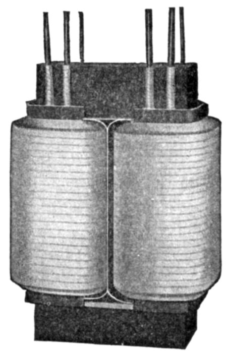
Fig. 1,941.—View showing mechanical construction of coil and core of Moloney pole type ½ to
50 kw. transformer. Moloney standard transformers of these sizes are regularly wound
for 1,100 to 2,200 primary volts. For 1,100 volts the primary coils are connected in
parallel by means of connecting links; for 2,200 volts, they are connected in series. The
porcelain primary terminal board is provided with two connecting links so that connections
can be made for either 1,100 or 2,200 volts.
This loss of energy as before explained is due to the work
required to change the position of the molecules of the iron,
in reversing the magnetization. Extra power then must be
taken from the line to make up for this loss, thus reducing the
efficiency of the transformer.
Ques. Upon what does the hysteresis loss depend?
Ans. Upon the quality of the iron in the core, the magnetic
density at which it is worked and the frequency.
[Pg 1398]
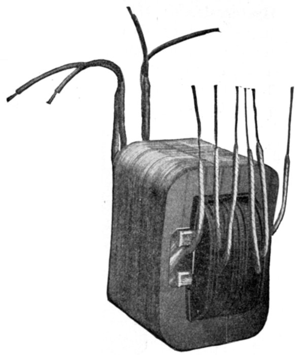
Fig. 1,942.—Fort Wayne transformer
coils and core complete.
Ques. With a given
quality of iron how
does the hysteresis
loss vary?
Ans. It varies as
the 1.6 power of the
voltage with constant frequency.
Ques. In construction, what
is done to obtain minimum
hysteresis loss?
Ans. The softest iron obtainable
is used for the core, and a
low degree of magnetization is
employed.
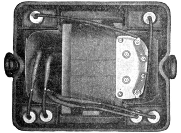
Fig. 1,943.—Top view of Fort Wayne (type A) transformer
cover removed, showing assembly of coils and core and
disposition of leads.
Eddy Currents.—The iron core
of a transformer acts as a closed
conductor in which small pressures
of different values
are induced in
different parts by the
alternating field, giving
rise to eddy currents.
Energy is thus
consumed by these
currents which is
wasted in heating the
iron, thus reducing
the efficiency of the
transformer.
[Pg 1399]
Ques. How is the loss reduced to
a minimum?
Ans. By the usual method of laminating
the core.
The iron core is built up of very thin sheet
iron or steel stampings, and these are insulated
from each other by varnish and are
laid face to face at right angles to the path
that the eddy currents
tend to follow,
so that the
currents would
have to pass from
sheet to sheet,
through the insulation.
Ques. In practice,
upon what
does the thickness
of the laminæ or
stampings depend?
Ans. Upon the
frequency.
The laminæ vary
in thickness from
about .014 to .025
inch, according as
the frequency is respectively
high or
low.
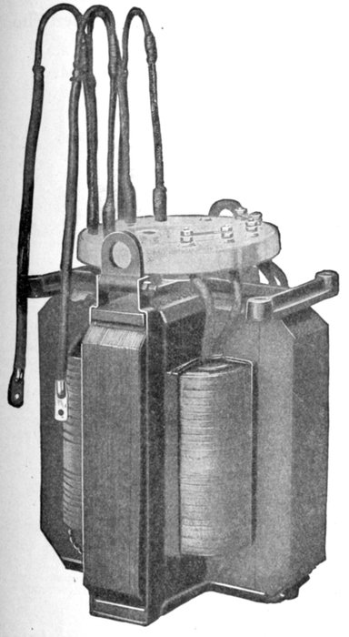
Fig. 1,944.—General Electric 10 kva., (type H) transformer removed from tank. That part
of the steel core composing the magnetic circuit outside of the winding is divided into four
equal sections. Each section is located a sufficient distance from the winding so that all
portions of the winding and core are equally exposed to the cooling action of the oil. On
all except the very smallest sizes the winding is divided by channels and ducts through
which a continual circulation of oil is maintained. The result is uniform temperature
throughout the transformer, thus eliminating the detrimental effects of unequal expansion
in the coils with consequent rubbing and abrasion of the insulation.
[Pg 1400]
Ques. Does a transformer take any current when the
secondary circuit is open?
Ans. Yes, a "no load" current passes through the primary.
Ques. Why?
Ans. The energy thus supplied balances the core losses.
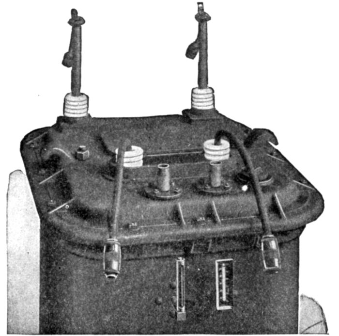
Fig. 1,945.—Cover construction of Wagner 350 kva., oil filled 1,100-2,200 volt transformer.
In transformers with corrugated cases, the base and top ring are cast to the corrugated
iron sheets.
Ques. Are the iron or copper losses the more important,
and why?
Ans. The iron losses, because these are going on as long as
the primary pressure is maintained, and the copper losses take
place only while energy is being delivered from the secondary.
[Pg 1401]
Strictly speaking, on no
load (that is when the
secondary circuit is open) a
slight copper loss takes place
in the primary coil but because
of its smallness is not
mentioned. It is, to be exact,
included in the expression
"iron losses," as the
precise meaning of this term
signifies not only the hysteresis
and eddy current losses but the
copper loss in the primary coil
when the secondary is open.
The importance of the
iron losses is apparent in
noting that in electric lighting
the lights are in use only
a small fraction of the 24
hours, but the iron losses
continue all the time, thus
the greater part of each day
energy must be supplied to
each transformer by the
power company to meet
the losses, during which time
no money is received from
the customers.
Some companies make a
minimum charge per month
whether any current is used
or not to offset the no load
transformer losses and rent
of meter.
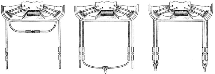
Figs. 1,946 to 1,948.—Methods of connecting the low tension sides of Westinghouse transformers using the connectors
illustrated in figs. 1,949 to 1,953.
Ques. How may the
iron losses be reduced to
a minimum?
Ans. By having short
magnetic paths of large area
and using iron or steel of
high permeability. The design
and construction must
keep the eddy currents as
low as possible.
[Pg 1402]
As before stated the iron losses take place continually, and since most
transformers are loaded only a small fraction of a day it is very important
that the iron losses should be reduced to a minimum.
With a large number of transformers on a line, the magnetizing current
that is wasted, is considerable.
During May, 1910, the U. S. Bureau of Standards issued a circular
showing that each watt saving in core losses was a saving of 88 cents,
which is evident economy in the use of high grade transformers.
Copper Losses.—Since the primary and secondary windings
of a transformer have resistance, some of the energy supplied
will be lost by heating the copper. The amount of this loss is
proportional to square of the current, and is usually spoken of
as the I2R loss.

Figs. 1,949 to 1,953.—Westinghouse low tension transformer connectors for connecting the
low tension leads to the feeder wires. The transformers of the smaller capacities have
knuckle joint connectors and those of the larger sizes have interleaved connectors. These
connectors form a mechanically strong joint of high current carrying capacity. Since the
high tension leads are connected directly to the cut out or fuse blocks, connectors are not
required on these leads. The use of these connectors allows a transformer to be removed
and another of the same or a different capacity substituted usually without soldering or
unsoldering a joint. The connectors also facilitate changes in the low tension connections.
Ques. Define the copper losses.
Ans. The copper losses are the sum of the I2R losses of both
the primary and secondary windings, and the eddy current loss
in the conductors.
Ques. Is the eddy current loss in the conductors large?
Ans. No, it is very small and may be disregarded, so that
the sum of the I2R losses of primary and secondary can be taken
as the total copper loss for practical purposes.
[Pg 1403]
Ques. What effect has the power factor on the copper
losses?
Ans. Since the copper loss depends upon the current in the
primary and secondary windings, it requires a larger current
when the power factor is low than when high, hence the
copper losses increase with a lowering of the power factor.
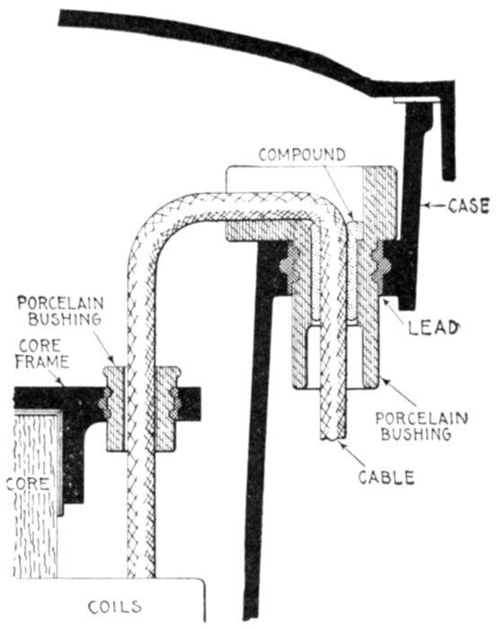
Fig. 1,954.—Method of bringing out the secondary leads in Wagner central station transformers.
Each primary lead is brought into the case through a similar bushing. Observe
the elimination of all possibility of grounding the cable on the case or core.
Ques. What effect other than heating has resistance
in the windings?
Ans. It causes poor regulation.
This is objectionable, especially when incandescent lights are in use,
because the voltage fluctuates inversely with load changes, that is,
it drops as lamps are turned on and rises as they are turned off, producing
disagreeable changes in the brilliancy of the lamps.
[Pg 1404]
Cooling of Transformers.—Owing to the fact that a
transformer is a stationary piece of apparatus, not receiving
ventilation from moving parts, its efficient cooling becomes a
very strong feature of the design, especially in the case of large
high pressure transformers. The effective cooling is rendered
more difficult because transformers are invariably enclosed in
more or less air tight cases, except in very dry situations, where a
perforated metal covering may be permitted.
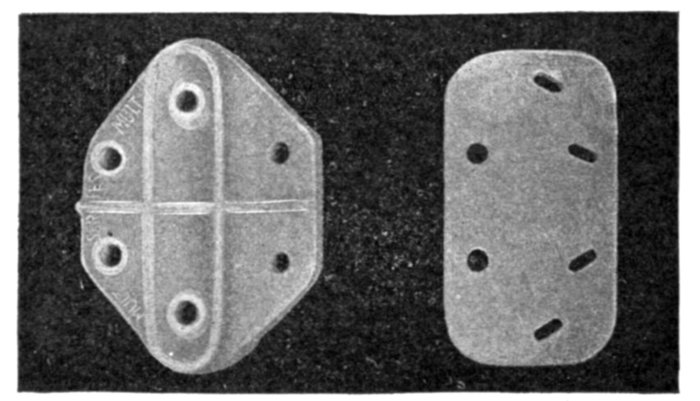
Figs. 1,955 and 1,956.—Westinghouse transformer terminal blocks for high and low tension
conductors.
The final degree to which the temperature rises after continuous
working for some hours, depends on the total losses
in iron and copper, on the total radiating surface, and on the
facilities afforded for cooling.
There are various methods of cooling transformers, the
cooling mediums employed being
- 1. Air;
- 2. Oil;
- 3. Water.
The means adopted for getting rid of the heat which is inevitably
developed in a transformer by the waste energy is one of
the important considerations with respect to its design.
[Pg 1405]
Ques. What is the behaviour of a transformer with
respect to heating when operated continuously at full
load?
Ans. The temperature gradually rises until at the end of
some hours it becomes constant.
The difference between the constant temperature and that of the
secondary atmosphere is called the temperature rise at full load. Its
amount constitutes a most important feature in the commercial value of the
transformer.

Figs. 1,957 to 1,960.—Porcelain bushing for Westinghouse transformers.
Ques. Why is a high rise of temperature objectionable?
Ans. It causes rapid deterioration of the insulation, increased
hysteresis losses, and greater fire risk.
Dry Transformers.—This classification is used to distinguish
transformers using air as a cooling medium from those which
employ a liquid such as water or oil to effect the cooling.
Air Cooled Transformers.—This name is given to all transformers
which are cooled by currents of air without regard to the
manner in which the air is circulated. There are two methods
of circulating the air, as by
- 1. Natural draught;
- 2. Forced draught, or blast.
[Pg 1406]
Ques. Describe a natural draught air cooled transformer.
Ans. In this type, the case containing the windings is open
at the top and bottom. The column of air in the case expands
as its temperature rises, becoming lighter than the cold air on
the outside and is consequently displaced by the latter, resulting
in a circulation of air through the case. The process is identical
with furnace draught.
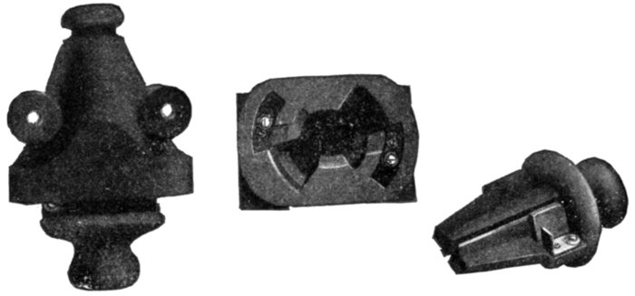
Figs. 1,961 to 1,963.—Fuse blocks for Westinghouse transformers. The fuses furnished with
the transformers are mounted in a weather proof porcelain fuse box of special design. The
stationary contacts are deeply recessed in the porcelain and are well separated from each
other. The contacts are so constructed that the plug is held securely in place by giving
it a partial turn after inserting it. When the plug is in position, the fuse is in sight and
its condition can be noted which eliminates all danger of pulling the fuse while same is
still intact and the transformer is under load.
Ques. Describe a forced draught or air blast transformer.
Ans. The case is closed at the bottom and open at the top.
A current of air is forced through from bottom to top as shown
in fig. 1,964 by a fan.
Ques. How are the coils best adapted to air cooling?
Ans. They are built up high and thin, and assembled with
spaces between them, for the circulation of the air.
[Pg 1407]
Ques. What are the requirements with respect to the
air supply in forced draught transformers?
Ans. Air blast transformers require a large volume of air at
a comparatively low pressure. This varies from one-half to one
ounce per square inch. The larger transformers require greater
pressure to overcome the resistance of longer air ducts.
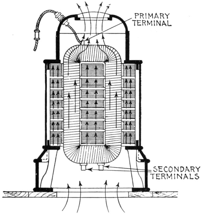
Fig. 1,964.—Forced draught or "air blast" transformer. As is indicated by the classification,
this type of transformer is cooled by forcing a current of air through ducts, provided between
the coils and between sectionalized portions of the core. The cold air is forced through
the interior of the core containing the coils by a blower, the air passing vertically through
the coils and out through the top. Part of the air is sometimes diverted horizontally
through the ventilating ducts provided in the core, passing off at one side of the transformer.
The amount of air going through the coils, or through the core, may be controlled
independently by providing dampers in the passages.
Ques. How much air is used ordinarily for cooling
per kw. of load?
Ans. About 150 cu. ft. of air per minute.
[Pg 1408]
In forced draught transformers, the air pressure maintained by the
blower varies from ½ to 1½ oz. per square inch. Forced draught or
air blast transformers are seldom built in small sizes or for voltages higher
than about 35,000 volts.
Oil Cooled Transformers.—In this type of transformer the
coils and core are immersed in oil and provided with ducts to
allow the oil to circulate by convection and thus serve as a
medium to transmit the heat to the case, from which it passes
by radiation.
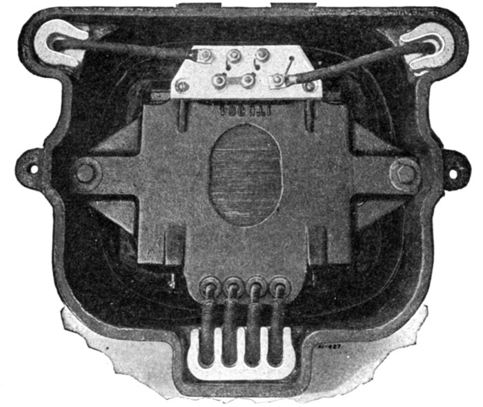
Fig. 1965.—Looking down into a Wagner central station transformer, showing the connection
board, which provides facility for varying the ratio of transformation and also for interchanging
the primaries.
Ques. Explain in detail the circulation of the oil.
Ans. The oil, heated by contact with the exposed surfaces
of the core and coils, rises to the surface, flows outward and[Pg 1409]
descends along the sides of the transformer case, from the outer
surface of which the heat is radiated into the air.
Ques. How may the efficiency of this method of cooling
be increased?
Ans. By providing the case with external ribs or fins, or by
"fluting" so as to increase the external cooling surface.
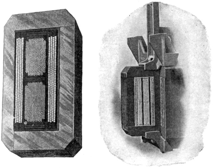
Fig. 1966.—Section through Westinghouse ½ kilovolt ampere type S transformer.
Fig. 1967.—Section through Westinghouse 50 kilovolt ampere type S transformer showing
large oil ducts.
Ques. In what types of transformer is this mode of
oil cooling used?
Ans. Lighting transformers.
In such transformers, the large volume of oil absorbs considerable heat,
so that the rise of temperature is retarded. Hence, for moderate periods[Pg 1410]
of operation, say 3 or 4 hours, the average lighting period, the maximum
temperature would not be reached.
Ques. In what other capacities except that of cooling
agent, does the oil act?
Ans. It is a good insulator, preserves the insulation from
oxidation, increasing the breakdown resistance of the insulation,
and generally restores the insulation in case of puncture.

Fig. 1,968.—Wagner 300 kva, 4,400 volt three phase oil cooled transformer. In this type of
transformer the case is filled with oil and fluted so as to increase the cooling surface, an oil
drain valve is screwed to a wrought iron nipple cast into the base, the duct to which is in such
a position as to make it possible not only to drain all of the oil from the transformer, but
when desirable, to draw off a small quantity from the bottom. Should any moisture be in
the oil it is therefore drawn off first.
Ques. What is the special objection to oil?
Ans. Danger of fire.
Ques. What kind of oil is used in transformers?
Ans. Mineral oil.
[Pg 1411]
Ques. What are the requirements of a good grade of
transformer oil?
Ans. It should show very little evaporation at 212° Fahr.,
and should not give off gases at such a rate as to produce an
explosive mixture with the air at a temperate below 356°. It
should not contain moisture, acid, alkali or sulphur compounds.
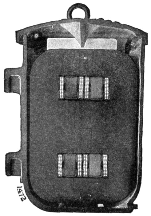
Fig. 1,969.—Section through Fort Wayne (type A) transformer showing interior of case, core
conductors, and insulation, also division of laminæ.
The presence of moisture can be detected by thrusting a red hot nail
in the oil; if the oil "crackle," water is present. Moisture may be
removed by raising the temperature slightly above the boiling point,
212° Fahr., but the time consumed (several days) is excessive.
[Pg 1412]
Water Cooled Transformers.—A water cooled transformer
is one in which water is the cooling agent, and, in most cases,
oil is the medium by which heat is transferred from the coils to
the water. In construction, pipes or a jacketed casing is provided
through which the cooling water is passed by forced circulation,
as shown in figs. 1,970 and 1,971.
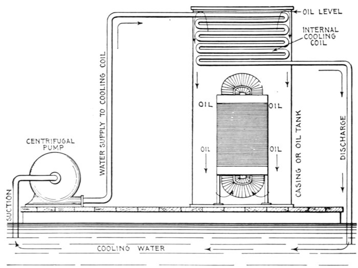
Fig. 1,970.—Water cooled transformer with internal cooling coil, that is, with cooling coil
within the transformer case. In this type, the cooling coil, through which the circulating
water passes, is placed in the top of the case or tank, the latter is filled with oil so that the
coil is submerged. The oil acts simply as a medium to transfer the heat generated by
the transformer to the water circulating through the cooling coil. In operation a continual
circulation of the oil takes place, as indicated by the arrows, due to the alternate heating
and cooling it receives as it flows past the transformer coils and cooling coil respectively.
In some cases tubular conductors are provided for the circulation
of the water.
Water cooled transformers may be divided into two classes,
as those having:
[Pg 1413]
- 1. Internal cooling coils;
- 2. External cooling coils.
Ques. Describe the first named type.
Ans. Inside the transformer case near the top is placed a
coil of wrought iron pipe, through which the cooling water is
pumped. The case is filled with oil, which by thermo-circulation
flows upward through the coils, transferring the heat absorbed
from the coils to the water; on cooling it becomes more dense
(heavier) and descends along the inside surface of the casing.
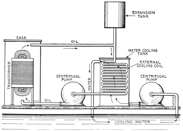
Fig. 1,971.—Water cooled transformer with external cooling coil. In this arrangement the
cooling coil is placed in a separate tank as shown. Here forced circulation is employed
for both the heat transfer medium (oil) and the cooling agent (water), two pumps being
necessary. The cool oil enters the transformer case at the lowest point and absorbing
heat from the transformer coils it passes off through the top connection leading to the
cooling coil and expansion tank. Since the transformer tank is closed, an expansion tank
is provided to allow for expansion of the oil due to heating. The water circulation is
arranged as illustrated.
[Pg 1414]
Ques. How much circulating water is required?
Ans. It depends upon the difference between the initial and
discharge temperatures of the circulating water.
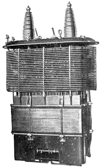
Fig. 1,972.—Interior of General Electric water cooled
140,000 volt transformer showing cooling coil.
Ques. In water
cooled transformers
how much cooling
surface is required
for an internal cooling
coil?
Ans. The surface of
the cooling coil should
be from .5 to 1.3 sq.
in. per watt of total
transformer loss, depending
upon the amount of
heat which the external
surface of the transformer
case will dissipate.
For a water temperature
rise of 43° Fahr.,
1.32 lbs. of water per
minute is required per
kw. of load.
Transformer Insulation.—This
subject
has not, until the last
few years, been given the same special attention that many
other electrical problems have received, although the development[Pg 1415]
of the transformer from its original form, consisting of an
iron core enclosed by coils of wire, to its present degree of refinement
and economy of material, has been comparatively rapid.
In transformer construction it is obviously very important
that the insulation be of the best quality to prevent burn outs
and interruptions of service.
Ques. What is the "major" insulation?
Ans. The insulation placed between the core and secondary
(low pressure) coils, and between the primary and secondary coils.
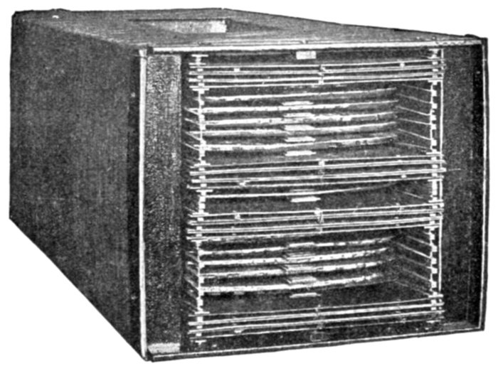
Fig. 1,973.—Assembled coils of General Electric water cooled 500 kva., 66,000 volt transformer.
It consists usually of mica tubes, sometimes applied as sheets held in
place by the windings, when no ventilating ducts are provided, or moulded
to correct form and held between sheets of tough insulating material
where ducts are provided for air or oil circulation.
Ques. Describe the "minor" insulation.
Ans. It is the insulation placed between adjacent turns of
the coils.
Since the difference of pressure is small between the adjacent turns
the insulation need not be very thick. It usually consists of a double[Pg 1416]
thickness of cotton wrapped around each conductor. For round conductors,
the ordinary double covered magnet wire is satisfactory.
Ques. What is the most efficient insulating material
for transformers?
Ans. Mica.
It has a high dielective strength, is fireproof, and is the most desirable
insulator where there are no sharp corners.
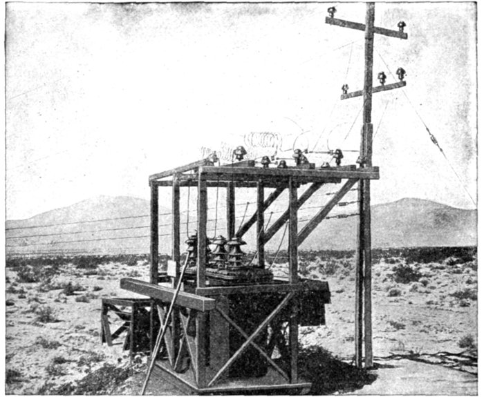
Fig. 1,974.—Three Westinghouse 20 kva, outdoor transformers, for irrigation service. These are
mounted on a drag so that they may be readily transported from place to place. 33,000
volts high tension; 2,200 and 440 volts low tension, 50 cycles. These outdoor transformers
are of the oil immersed, self-cooling type and have been developed to meet the
requirements for transformers of capacities greater or of voltages higher than are usually
found in distribution work. They are in reality distributing transformers for high voltage,
outdoor installations, single or three phase service, for voltages up to 110,000. Where
the magnitude of the load does not warrant an expensive installation, transformers of
the outdoor type are particularly applicable. The cost of a building and outlet bushings
which is often the item of greatest expense is eliminated where outdoor type transformers
are installed.
[Pg 1417]
Oil Insulated Transformers.—High voltage transformers
are insulated with oil, as it is very important to maintain careful
insulation not only between the coils, but also between the coils
and the core. In the case of high voltage transformers, any
accidental static discharge, such as that due to lightning, which
might destroy one of the air insulated type, might be successfully
withstood by one insulated with oil, for if the oil insulation
be damaged it will mend itself at once.
By providing good circulation for the oil, the transformer can
get rid of the heat produced in it readily and operate at a low
temperature, which not only increases its life but cuts down
the electric resistance of the copper conductors and therefore
the I2R loss.
Efficiency of Transformers.—The efficiency of transformers
is the ratio of the electric power delivered at the secondary terminals
to the electric power absorbed at the primary terminals.
Accordingly, the output must equal the input minus the
losses. If the iron and copper losses at a given load be known,
their values and consequently the efficiency at other loads may
be readily calculated.
EXAMPLE.—If a 10 kilowatt constant pressure transformer
at full load and temperature have a copper loss of .16 kilowatt,
or 1.6 per cent., and the iron loss be the same, then its
At three-quarters load the output will be 7.5 kilowatts; and as
the iron loss is practically constant at all loads and the copper
loss is proportional to the square of the load, the
The matter of efficiency is important, especially in the case of
large transformers, as a low efficiency not only means a large
waste of power in the form of heat, but also a great increase in
the difficulties encountered in keeping the apparatus cool.
The efficiency curve shown in fig. 1,975, serves to indicate, however,
how slight a margin actually remains for improvement in
this particular in the design and construction of large transformers.
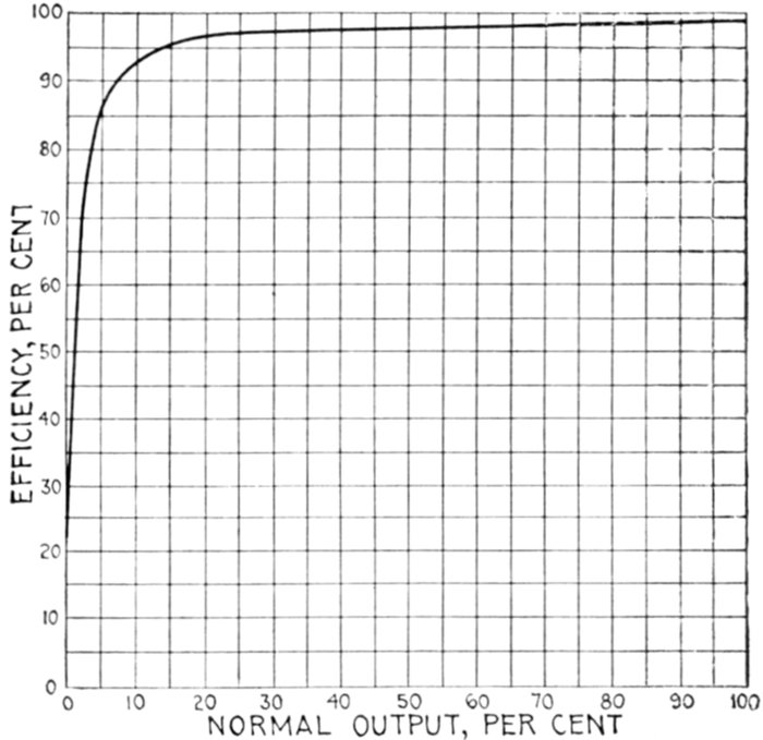
Fig. 1,975.—Efficiency curve of Westinghouse 375 kw., transformer. Pressure 500 to 15,000
volts; frequency 60. Efficiencies at different loads: full load efficiency, 98%; ¾ full
load efficiency, 98%; ½ full load efficiency, 97.6%; ¼ full load efficiency, 96.1%; regulation
non-inductive load, 1.4%; load having .9 power factor, 3.3%.
The efficiency of transformers is, in general, higher than that of other
electrical machines; even in quite small sizes it reaches over 90 per cent.,
and in the largest, is frequently as high as 98.5 per cent.
To measure the efficiency of a transformer directly, by measuring
input and output, does not constitute a satisfactory method when the
efficiency is so high. A very accurate result can be obtained, however,
by measuring separately, by wattmeter, the core and copper losses.
The core loss is measured by placing a wattmeter in circuit when the
transformer is on circuit at no load and normal frequency.
[Pg 1419]
The copper loss is measured by placing a wattmeter in circuit with the
primary when the secondary is short circuited, and when enough pressure
is applied to cause full load current to flow.
If it be desired to separate the load losses from the true I2R loss, the
resistances can be measured, and the I2R loss calculated and subtracted
from the wattmeter reading. The losses being known, the efficiency at
any load is readily found by taking the core loss as constant and the
copper loss as varying proportionally to the square of the load. Thus,
All Day Efficiency of Transformers.—This denotes the ratio
of the total watt hour output of a transformer to the total watt
hour input taken over a working day. To compute this efficiency
it is necessary to know the load curve of the transformer
over a day. Suppose that this is equivalent to 5 hours at full load,
and 19 hours at no load. Then, if W1 be the core loss in watts,
W2 the copper loss at rated load, and W the rated output,
- output = 5 × W,
- losses = 5 (W1 + W2) + 19 W1,
- input = 5 (W + W1 + W2) + 19 W1,
and the all day efficiency is equal to
Commercial or all day efficiency is a most important point in
a good transformer. The principal factor in securing a high all
day efficiency is to keep the core loss as low as possible. The
core loss is constant—it continues while current is supplied to
the primary, while copper loss takes place only when the secondary
is delivering energy.
In general, if a transformer is to be operated at light loads
the greater part of the day, it is much more economical to use
one designed for a small iron loss than for a small full load
copper loss.
[Pg 1420]

Figs. 1,976 and 1,977.—Westinghouse double pole fuse box; views showing box open with tubes in place, and with tubes removed.
Transformer Fuse
Blocks.—These may be of
either the single pole or double
pole type. Fig. 1,976 shows a
double pole fuse box opened,
and fig. 1,977, the fuse box
opened and the tubes removed.
Of the four wires,
W, W, W, W, entering the
box from beneath, two are
from the primary mains, and
two lead to the primary coil
of the transformer. These
wires terminate in metallic
receptacles R, R, R, R, in the
porcelain plate P, fig. 1,977,
which are bridged over in
pairs by fuse wires placed inside
porcelain tubes T, T, as
shown in fig. 1,976. These
tubes are air tight except for
a small outlet O in each,
which fit into the receptacles
B, B, in the porcelain plate
and open out at the back of
the block, as shown in fig. 1,977.
The fuse wires are connected
between metallic spring
tubes S, S, S, S, which fit into
the receptacles R, R, R, R.
If a sudden load or a short
circuit occur in the transformer,
the intense heat,[Pg 1421]
accompanying the melting or blowing of the fuse, causes a rapid
expansion of the air inside the tube, so that a strong blast of air
rushes through the outlet O of the tube and immediately extinguishes
the arc.
By this arrangement, sustained arcing is prevented, as the action of
the tube causes the arc to extinguish itself automatically when the
current is interrupted.
The porcelain tubes are held in position by the spring K, and the
primary of the transformer becomes entirely disconnected from the
circuit when the tubes are lifted out.
This form of construction enables the lineman to detach the tubes
from the fuse box, and insert the fuse at his convenience. Furthermore,
when inserting a fuse in a short circuited line, he does not run the risk of
being hurt, as the heated vapor of the exploding fuse can escape through
the outlet provided for that purpose, and in a predetermined direction.
The method of attaching the lid not only permits of quick access to
the interior of the box, but enables the lineman to tighten the joints
by means of the thumb screws L, L, so as to keep the box waterproof.
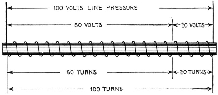
Fig. 1,978.—Diagram illustrating connections and principles of auto-transformers as explained
in the accompanying text.
Auto-transformers.—In this class of transformer, there is
only one winding which serves for both primary and secondary.
On account of its simplicity it is made cheaply.
Auto-transformers are used where the ratio of transformation is small,
as a considerable saving in copper and iron can be effected, and the whole
transformer reduced in size as compared with one having separate windings.
[Pg 1422]
Fig. 1,978 illustrates the electrical connections and the relations
between the volts and number of turns.
By using the end wire and tapping in on turn No. 20 a current at 20
volts pressure is readily obtained which may be used for starting up
motors requiring a large starting current and yet not draw heavily on
the line.
Since the primary is connected directly to the secondary it would be
dangerous to use an auto-transformer on high pressure circuits. This
type of transformer has only a limited use, usually as compensator for
motor starting boxes.
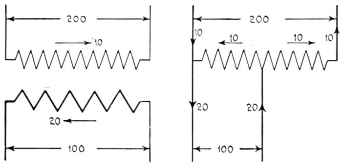
Figs. 1,979 and 1,980.—Two winding transformer and single winding or auto-transformer.
Fig. 1,979 shows a 200:100 volt transformer having a 10 amp. primary and a 20 amp. secondary,
the currents being in opposite directions. If these currents be superposed by using
one winding only, the auto-transformer shown in fig. 1,980 is obtained where the winding
carries 10 amp. only and requires only one-half the copper (assuming the same mean
length of turn). If R be the ratio of an auto-transformer, the relative size of it compared with
a transformer of the same ratio and output is ((R - 1) / R):1. For example, a 10 kw. transformer
of 400 volts primary and 300 volts secondary could be replaced by an auto-transformer
of 10 × (1.33 - 1) / 1.33 = 2.5 kw.; or, in other words, the amount of material used
in a 2½ kw. transformer could be used to wind an auto-transformer of 400:300 ratio and
10 kw. output.
Constant Current Transformers for Series Arc Lighting.—The
principle of the constant current transformer as
used for series arc lighting is readily understood by reference[Pg 1423]
to the elementary diagram shown in fig. 1,981. A constant
alternating current is supplied to the stationary primary coil
which induces a current in the movable secondary coil. The
pressure induced in the coil will depend on the number of lines
of flux which pass through it and by changing its position in
the magnetic field over the primary a variable e.m.f. can be
produced and a constant current maintained in the lighting
circuit when the lamps are turned on or off, or if the resistance
of the circuit be lowered by the consumption of the carbons.
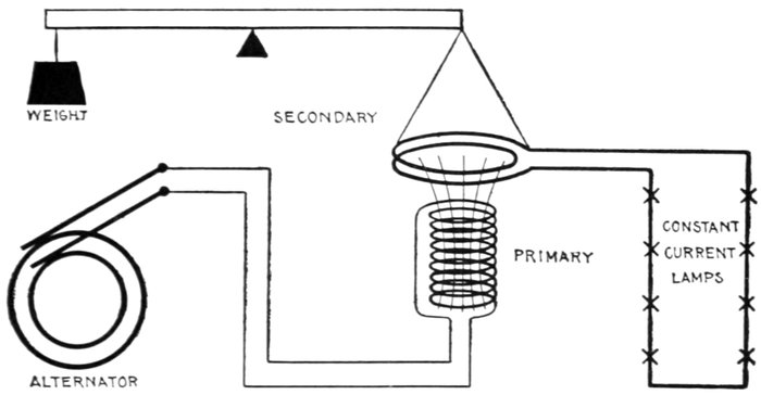
Fig. 1,981.—Elementary diagram illustrating the principles of constant current transformer
as used for series arc lighting.
Since the induced currents in the secondary are repelled by
the primary there is a tendency for the secondary coil to jump
out of the primary field, and in case of a very large current due
to a short circuit in the lamp circuit, the secondary current is
quickly reduced to normal by the rapid movement of the coil
upward.
By adjusting the counterweight for a given number of amperes
required by the arc, the current will be maintained constant
by the movement of the secondary coil.
[Pg 1424]
The magnetic field produced by the primary must be kept
the same by a constant current from the alternator, therefore,
when the lamp load is increased the primary voltage increases
similar to that of an ordinary series wound direct current
dynamo. In other words the alternator and regulating transformer
supply a constant current and variable voltage.

Fig. 1,982.—Mechanism of General Electric air cooled constant current transformer. It
operates on the principle explained in the accompanying text and is built to supply 25 to
100 arc lamps at 6.6 to 7.5 amperes. The transformers are interchangeable and will
operate on 60 or 125 cycles. The relative positions of the two coils may be changed in order
to regulate the strength of the current more closely, by shifting the position of the arc
carrying the counterbalance by means of the adjusting screw on it. A dash pot filled with
special oil prevents sudden movements of the secondary coil and keeps the current through
the lamps nearly constant, when they are being cut in or out of the circuit. In starting
up a constant current transformer, it is necessary to separate the two coils as far as possible
and then close the primary circuit switch and allow the two coils to come together.
If the primary circuit be thrown directly on the generator the heavy rush of current which
will follow due to the two coils being too close together might injure the lamps.
Constant current incandescent lighting systems for use in
small towns also use this method for automatically regulating
the current.
[Pg 1425]
Regulation.—This term applies to the means adopted either
to obtain constancy of pressure or current. In the transformer,
regulation is inherent, that is, the apparatus automatically
effects its own regulation. The regulation of a transformer
means, the change of voltage due to change of load on the secondary;
it may be defined more precisely as: the percentage increase in
the secondary voltage as the load is decreased from its normal value
to zero. Thus, observation should be made of the secondary
voltage, at full load and at no load, the primary pressure being
held constant at the normal value.
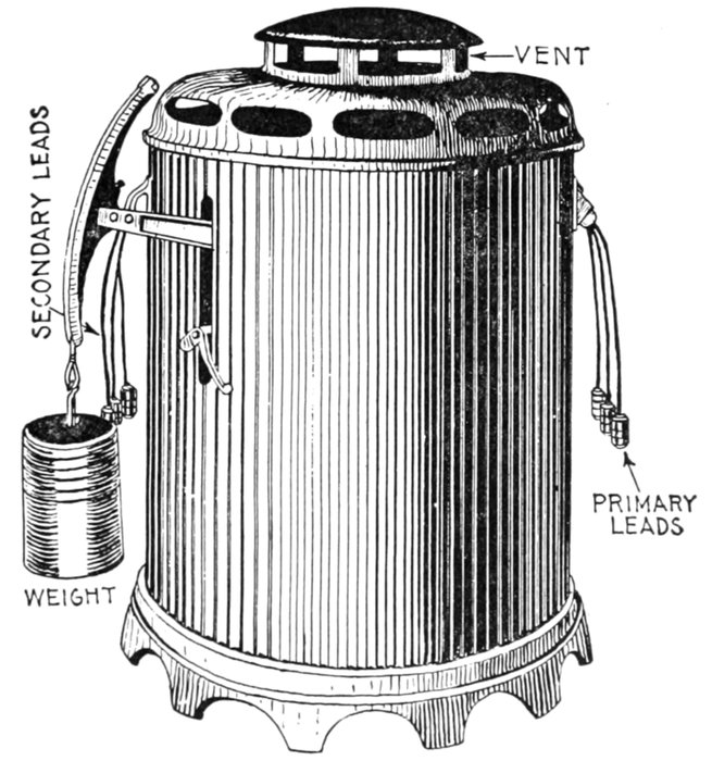
Fig. 1,983.—General Electric air cooled constant current transformer. View showing external
appearance with case on.
The regulation is said to be "good" or "close," when this change is
small. In the design of a transformer, good regulation and low iron
losses are in opposition to one another when the best results are desired in[Pg 1426]
both. A well designed transformer,
however, should give
good results, both as to regulation
and iron losses, the relative
value depending upon the class
of work it has to do, and size.
Transformer Connections.—The
alternating current
has the advantage over
direct current, in the ease with
which the pressure and current
can be changed by different
connections of transformers.
On single phase circuits the
transformer connections can
be varied to change current
and pressure, and in addition
on polyphase circuits the
phases can also be changed to
almost any form.
Single Phase Connections.—The
method of connecting
ordinary distributing
transformers to constant pressure
mains is shown by the
elementary diagram, fig. 1,984,
where a transformer of 10 to
1 ratio is indicated with its
primary winding connected to
a 1,000 volt main, and a
secondary winding to deliver
100 volts.
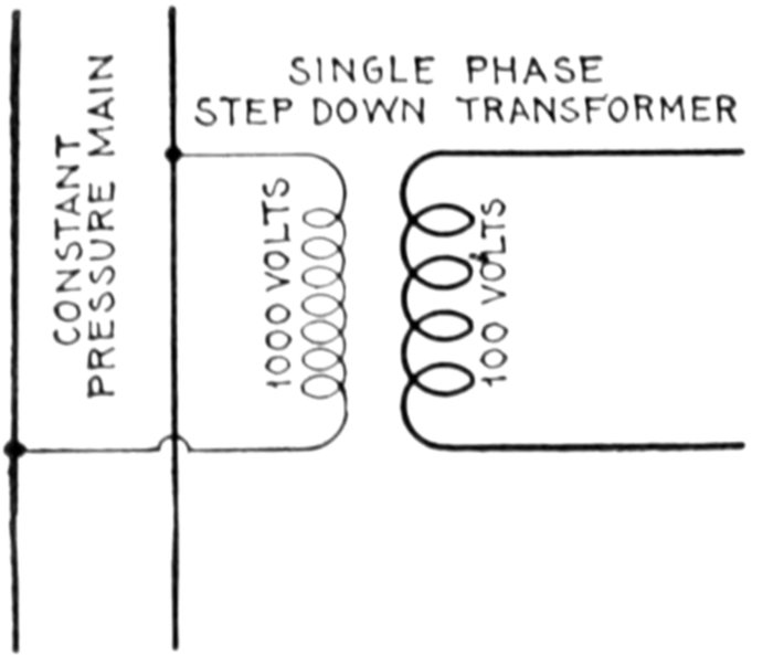
Fig. 1,984.—Single phase transformer connection with constant pressure main.
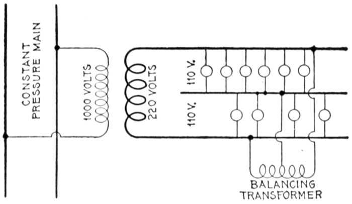
Fig. 1,985.—Usual method of single phase transformer connections for residence lighting with three wire secondaries. A balancing
transformer is connected to the three wire circuit near the center of distribution as shown.
[Pg 1427]
Fig. 1,986 shows a transformer with each winding divided into
two sections. Each primary section is wound for 1,000 volts,
and each secondary section for 50 volts. By connecting the
entire primary winding in series, the transformer may be supplied
from a 2,000 volt main, as indicated, and if the secondary
winding be also connected all in series, as shown, the no load
voltage will be 100 between the secondary terminals.
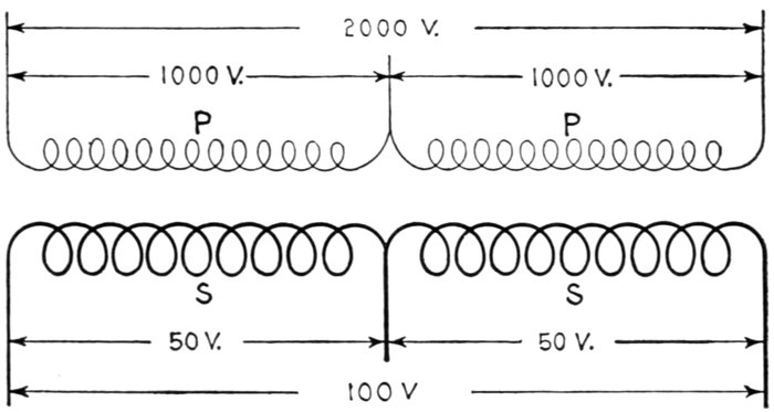
Fig. 1,986.—Diagram of single phase transformer having primary and secondary windings in
two sections, showing voltages per section with series connections.
The sections of the primary winding may be connected in
parallel to a 1,000 volt main, and 100 volts obtained from the
secondary, or the primary and secondary windings may be
connected each with its two sections in parallel, and transformations
made from 1,000 to 50 volts as represented in fig. 1,987.
This is a very common method of construction for small transformers,
which are provided with convenient terminal blocks for combining the
sections of each winding to suit the requirements of the case. When
the two sections of either winding are connected in parallel as shown in
fig. 1,987, care must be taken to connect corresponding ends of the two
sections together.
[Pg 1428]
Combining Transformers.—Two or more transformers
built to operate at the same pressure and frequency may be connected
together in a variety of ways; in fact, the primary and
secondary terminals may each be considered exactly as the
terminals of direct current dynamos, with certain restrictions.
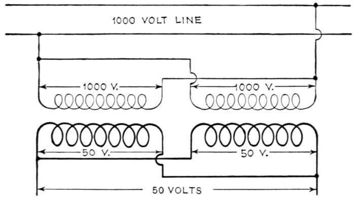
Fig. 1,987.—Diagram of single phase transformer with primary and secondary windings of two
sections each, showing voltages per section with parallel connection.
Ques. What are the two principal precautions which
must be observed in combining transformer terminals?
Ans. The terminals must have the same polarity at a given
instant, and the transformers should have practically identical
characteristics.
The latter condition is not absolutely essential, but it is emphatically
preferable. For example, if a transformer, which has 2 per cent. regulation,
be connected in parallel, as indicated in fig. 1,988, with one which
has 3 per cent. regulation, at no load the transformers will give exactly
the same voltage at the secondary terminals, but at full load one will
have a secondary pressure of, say, 98 volts, while the other has 97 volts.
The result is that the transformer giving only 97 volts will be subject[Pg 1429]
to a reverse pressure of one volt from its mate. This will not cause
excessive current to flow backward through the secondary winding of
the low voltage transformer, but it will disturb the phase relations and
lower the power factor and efficiency of the combination. In such a
case it is much better to work the secondary circuits of the two transformers
separately.
In case the transformers have practically the same characteristics it
is necessary, as stated above, to make sure that the secondary terminals
connected together have the same polarity at a given instant; it is not
necessary to find out definitely what the polarity is, merely that it is the
same for both terminals. This can be easily done as shown in fig. 1,989.
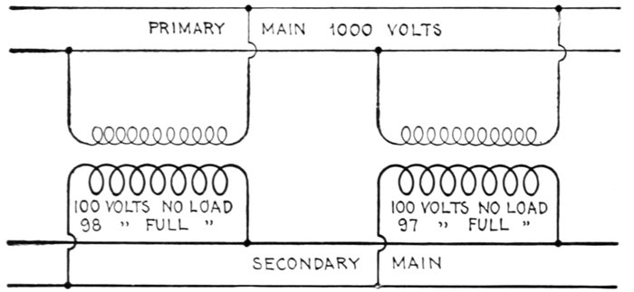
Fig. 1,988.—Diagram showing unlike single phase transformers in parallel.
Ques. What may be said with respect to operating
transformer secondaries in parallel?
Ans. It is seldom advantageous. Occasionally it may be
necessary as a temporary expedient, but where the load is such as
to require a greater capacity than that of a transformer already installed,
it is much better to replace it by a large transformer than
to supplement it by an additional transformer of its own size.
Ques. How are the secondaries arranged in modern
transformers and why?
Ans. The secondary windings are divided into at least two
sections so that they may be connected either in series or parallel.
[Pg 1430]
Ques. Explain how secondary connections are made
for different voltages.
Ans. If, for instance, the secondary pressure of a transformer
having two sections be 100 volts with the terminals in
parallel, as in fig. 1,990, then connecting them in series will give
200 volts at the free secondary terminals, as indicated in fig. 1,991.
Ques. What precaution should be taken in connecting
secondary sections in parallel in core type if the two
sections be wound on different limbs of the cores?
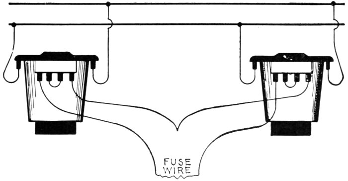
Fig. 1,989.—Method of comparing instantaneous polarity. Two of the terminals are connected
as shown by a small strip of fuse wire, and then touching the other two terminals
together. If the fuse blows, then the connections must be reversed; if it does not, then
they may be made permanent.
Ans. It will be advisable to make the connections ample
and permanent, so that there will not be any liability to a
difference between the current flowing in one secondary winding
and that flowing through the other.
Two Phase Connections.—In the case of two phase distribution
each circuit may be treated as entirely independent
of the other so far as the transformers are concerned. Two[Pg 1431]
transformers are used, one being
connected to one primary
phase and supplying one
secondary phase, the other
being connected to the other
primary phase and supplying
the other secondary phase as
indicated in fig. 1,996, exactly
as though each primary and
secondary phase were an ordinary
single phase system, independent
of the other phase.

Figs. 1,990 and 1,991.—Methods of altering the secondary connections of a transformer having two sections in the secondary to
obtain a different voltage. Fig. 1,990 shows the two sections in parallel giving say 100 volts; fig. 1,991 shows the two sections
in series giving 200 volts.
Ques. Is the above
method usually employed?
Ans. No, the method shown
in fig. 1,997 is generally used.
Three Phase Connections.—There
is not so much freedom
in making three phase
transformer connections, as
with single or two phase, because
the three phases are
inseparably interlinked. However,
the system gives rise to
several methods of transformer
connection, which are known as:
- 1. Star;
- 2. Delta;
- 3. Star-delta;
- 4. Delta-star.
[Pg 1432]
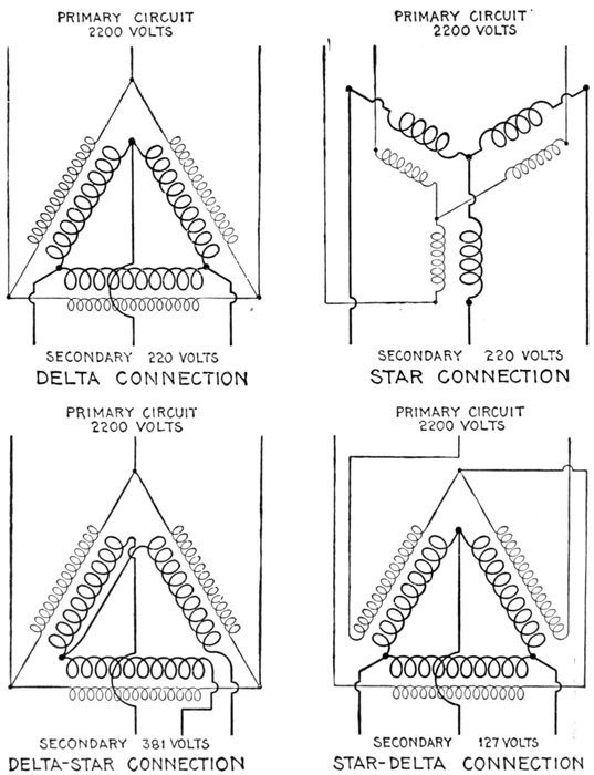
Figs. 1,992 to 1,995.—Three phase transformer connections. Fig. 1,992 delta connection;
fig. 1,993 star connection; fig. 1,994 delta star connection; fig. 1,995 star-delta connection.
[Pg 1433]
Delta Connection.—In the delta connection both primaries and
secondaries are connected in delta grouping, as in fig. 1,992.
Star Connection.—This method consists in connecting both the
primaries and secondaries in star grouping, as in fig. 1,993.
Delta-star Connection.—In this method the primaries are connected
in delta grouping and the secondaries in star grouping, as in
fig. 1,994.
Star-delta Connection.—This consists in connecting the primaries
in star grouping, and the secondaries in delta grouping, as in fig. 1,995.
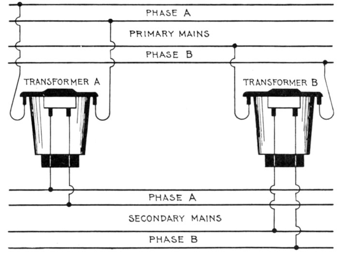
Fig. 1,996.—Two phase transformer connections. Two single phase transformers are used
and connections made just as though each phase were an ordinary single phase system.
Ques. What advantage has the star connection over
the delta connection?
Ans. Each star transformer is wound for only 58% of the
line voltage. In high voltage transmission, this admits of much
smaller transformers being built for high pressure than possible
with the delta connection.
[Pg 1434]
Ques. What advantages are obtained with the delta
connection?
Ans. When three transformers are delta connected, one
may be removed without interrupting the performance of the
circuit, the two remaining transformers in a manner acting in
series to carry the load of the missing transformer.
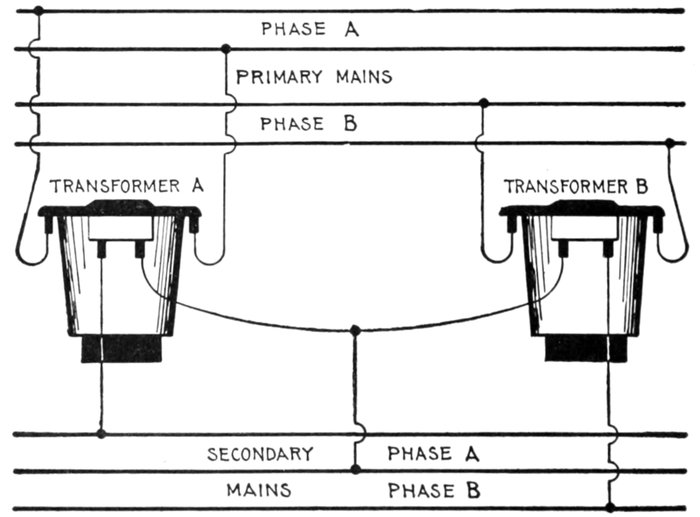
Fig. 1,997.—Two phase transformer connections, with secondaries arranged for three wire
distribution, the primaries being independently connected to the two phases. In the
three wire circuit, the middle or neutral wire is made about one-half larger than each of
the two outer wires. In fig. 1,996 it makes no difference which secondary terminal of a transformer
is connected to a given secondary wire, so long as no transformers are used in
parallel. For example, referring to the diagram, the left hand secondary terminal of
transformer, A, could just as well be connected to the lower wire of the secondary phase,
A, and its right hand terminal connected to the upper wire, the only requirement being
that the two pairs of mains shall not be "mixed"; that is, transformer, A, must not be connected
with one secondary terminal to phase, A and the other to phase, B. In the case
shown by fig. 1,997, there is not quite so much freedom in making connections. One
secondary terminal of each transformer must be connected to one of the outer wires and
the other two terminals must be both connected to the larger middle wire of the secondary
system. It makes no difference, however, which two secondary terminals are joined and
connected to the middle wire so long as the other terminal of each transformer is connected
to an outer wire of the secondary system.
The desire to guard against a shut down due to the disabling of one
transformer has led to the extensive use of the delta connection, especially
for the secondaries or low pressure side.
[Pg 1435]
It should be noted that if one transformer be disabled, the efficiency
of the other two will be greatly reduced. To operate a damaged
three phase transformer, the damaged windings must be separated
electrically from the other coils, the damaged primary and secondary
being respectively short circuited upon themselves.
Ques. What kinds of transformers are used for three
phase current?
Ans. Either a three phase transformer, or a separate single
phase transformer for each phase.
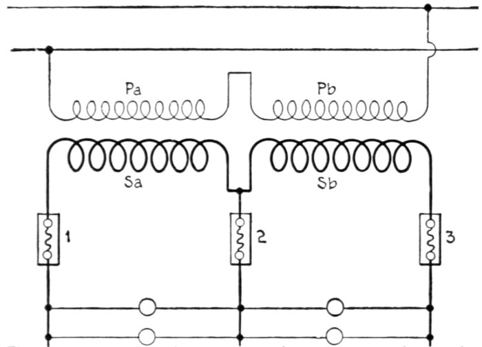
Fig. 1,998.—Three wire connections for transformer having two secondary sections on different
legs of the core. If the secondary terminals be connected up to a three wire distribution,
as here shown diagrammatically, it is advisable to make the fuse, 2, in the middle wire,
considerably smaller than necessary to pass the normal load in either side of the circuit,
because, should the fuse, 1, be blown, the secondary circuit through the section, Sa, will
be open, and the corresponding half of the primary winding, Pa, will have a much higher
impedance than the half of the primary winding, Pb, the inductance of which is so nearly
neutralized by the load on the secondary winding, Sb. The result will be that the voltage of
the primary section, Pa, will be very much greater than that of the section, Pb, and as the
sections are in series the current must be the same through both halves of the winding;
the drop or difference of pressure, therefore, between the terminals of Pa will be much
higher than that between the terminals of Pb, consequently, the secondary voltage of Sb
will be greatly lowered and the service impaired. As the primary winding, Pa, is designed
to take only one-half of the total voltage, the unbalancing referred to will subject it to a
considerably higher pressure than the normal value; consequently, the magnetic density
in that leg of the transformer core will be much higher than normal, and the transformer
will heat disastrously. If the fuse, 2, in the middle wire be made, say, one-half the capacity
of each of the other fuses, this condition will be relieved by the blowing of this fuse,
and as the lamps in the live circuit would not be anywhere near candle power if the circuit
remained intact, the blowing of the middle fuse will not be any disadvantage to the user
of the lamps. Some makers avoid the contingency just described by dividing each secondary
coil into two sections and connecting a section on one leg in series with a section
on the other leg of the core, so that current applied to either pair of the secondary terminals
will circulate about both legs of the core.
[Pg 1436]
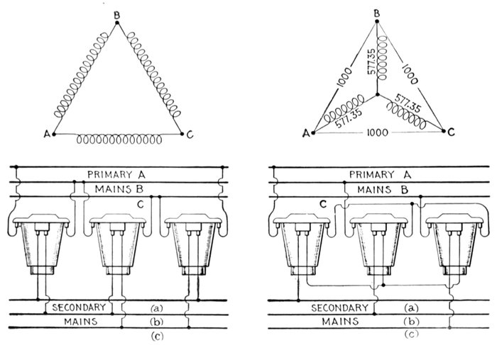
Figs. 1,999 to 2,002.—Three phase delta, and star connections using three transformers. There are two ways of connecting
up the primaries and secondaries, one known as the "delta" connection, and illustrated diagrammatically by fig. 1,999,
and the other known as the "star" connection, and illustrated by fig. 2,001. In both diagrams the line wires are lettered,
A, B and C. Fig. 2,000 shows the primaries and secondaries connected up delta fashion, corresponding to fig. 1,999, and
fig. 2,002 shows them connected up star fashion, corresponding to fig. 2,001. In both of the latter sketches the secondary
wires are lettered to correspond with the respective primary wires. When the primaries are connected up delta fashion,
the voltage between the terminals of each primary winding is the same as the voltage between the corresponding two wires
of the primary circuit, and the same is true of the secondary transformer terminals and circuit wires. The current, however,
flowing through the transformer winding is less than the current in the line wire, for the reason that the current from
any one line wire divides between the windings of two transformers. For example, in figs. 1,999 and 2,000, part of the
current from the line wire, A, will flow from A to B through the left hand transformer, and part from A to C through the
right hand transformer; if the current in the line wire, A, be 100 amperes, the current in each transformer winding will be
57.735 amperes. When transformers are connected up star fashion, as in figs. 2,001 and 2,002, the current in each transformer
winding is the same as that in the line wire to which it is connected, but the voltage between the terminals of each
transformer winding is 57.735 per cent. of the voltage from wire to wire on the circuit. For example, if the primary voltage
from A to B is 1,000 volts, the voltage at the terminals of the left hand transformer (from A to J) will be only 577.35 volts,
and the same is true of each of the other transformers if the system is balanced. These statements apply, of course, to
both primary and secondary windings, from which it will become evident that if the three transformers of a three phase
circuit be connected up star fashion at the primaries, and delta fashion at the secondaries, the secondary voltage will be
lower than if both sides are connected up star fashion. For example, if the transformers be wound for a ratio of 10 to 1,
and are connected up with both primaries and secondaries alike, no matter whether it be delta fashion or star fashion, the
secondary voltage will be one-tenth of the primary voltage; but if the primaries be connected up star fashion on a 1,000
volt circuit, and the secondaries be connected up delta fashion, the secondary voltage will be only 57.735 volts, instead of
100 volts. The explanation of the difference between the voltage per coil in a delta system and that in a star system is that
in the former each winding is connected directly across from wire to wire; whereas in the star system, two windings are in
series between each pair of line wires. The voltage of each winding is not reduced to one-half, however, because the pressures
are out of phase with each other, being 120°, or one-third of a cycle, apart; consequently, instead of having 500 volts at
the terminals of each coil in fig. 2,001 the voltage is 577.35. The same explanation applies to the current values in a delta system.
The current phase between A and B, in fig. 1,999, is 120° removed from that in the winding between A and C; consequently
the sum of the two currents, in the wire, A, is 1.732 times the current in each wire; or, to state it the opposite way, the
current in each winding is 57.735% of the current in the wire, A. It will be well for the reader to remember that in all cases
pressures differing in phase when connected in series, combine according to the well-known law of the parallelogram of
forces; currents differing in phase, and connected in parallel, combine according to the same law.
Ques. What points
are to be considered
in choosing between
three phase and single
phase transformers
for the three phase current
transformation?
Ans. No specific rule
can be given regarding
the selection of single
phase or three phase
transformers since both
designs are equally reliable;
local conditions
will generally determine
which type is preferable.
The following general
remarks may, however,
be helpful:
Single phase transformers
are preferable where
only one transformer
group is installed and
where the expense of a
spare transformer would
not be warranted. In such
installations the burn out
of one phase of a three
phase unit would cause
considerable inconvenience
for the reason that
the whole transformer
would have to be disconnected
from the circuit
before repairs could be
made.
If single phase transformers
be used and connected
in delta on both
primary and secondary,[Pg 1438]
the damaged transformer can be cut out with a minimum amount of
trouble and the other two transformers can be operated at normal temperature
open delta at 58 per cent. of the normal capacity of the group
of three transformers, until the third unit can be replaced.
With a three phase shell type transformer, if both the primary and
secondary be delta connected, trouble in one phase will not prevent the
use of the other two phases in open delta. By short circuiting both
primary and secondary of the defective phase, and cutting it out of
circuit the magnetic flux in that section is entirely neutralized. This
cannot be done, however, with any but delta connected shell type
transformers.
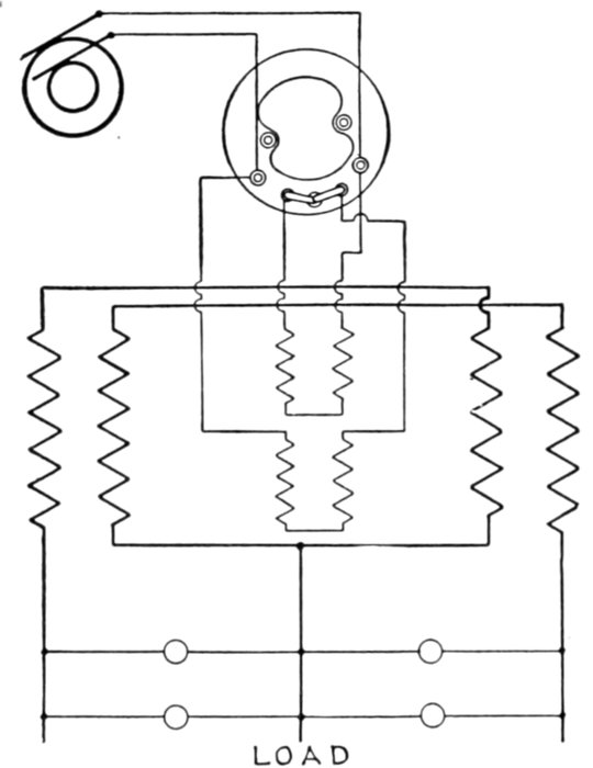
Fig. 2,003.—Diagram showing three wire secondary connections General Electric (type H)
transformer. As will be seen, the method adopted consists of distributing equally, on
each side of the primary coil, both halves of the secondary winding, so that each secondary
throughout its length is closely adjacent to the entire primary winding. In order to
insure the exact equality of resistance and reactance in the two secondary windings necessary
to obtain perfect regulation of the two halves, the inside portion of the secondary
winding on one side of the primary coil is connected in series with the outside portion of
that on the other side. As a result, the drop of voltage in either side of the secondary
under any ordinary conditions of unbalanced load, does not exceed the listed regulation
drop. This particular arrangement is used because it is the simplest and best method for
this construction.
Where a large number of three phase transformers can be used, it is
generally advisable to install three phase units, the following advantages
being in their favor as compared with single phase units:
[Pg 1439]
- 1. Require less floor space than three single phase units;
- 2. Weigh less than the single phase units;
- 3. Simpler connections, as only three primary and three secondary leads are generally brought out;
- 4. Transformer presents a symmetrical and compact appearance.
Ques. What is the character of the construction of
three phase transformers?
Ans. The three phase transformer is practically similar
to that of the single phase, except that somewhat heavier and
larger parts are required for the core structure.
| COMPARISON OF AIR BLAST, WATER COOLED, AND OIL COOLED TRANSFORMERS |
| Air blast type |
Water cooled type |
Oil cooled type |
| [8]
NOTE.—No special foundations are necessary for any type
of transformer other than a good, even floor, having sufficient
strength to support the weight. |
| 1. COST |
| A. First cost |
|
|
| Necessarily more expensive than the water cooled type of similar rating. |
Least expensive of all types. |
Necessarily more expensive than the air blast and water cooled type of similar rating. |
| B. |
|
|
The installation is extremely simple.
Moisture that
may have collected on the surfaces during transportation or
storage should be thoroughly dried out. |
Being heavier than the air blast type, these transformers,
as a rule, require heavier apparatus for installing. Both
transformer and tank should be thoroughly dried out before
being filled with oil.
The oil is usually supplied in 50
gal. hermetically sealed steel barrels to minimize possibility
of moisture during transportation. |
Being heavier than the air blast and water cooled
type, these transformers require heavier apparatus
for installing. Both transformer and tank should be
thoroughly dried out before being filled with oil.[Pg
1440][Pg
1441] |
| C. Auxiliary apparatus |
|
|
A duct, or chamber, of considerable size is required
under the transformers in order to conduct the cooling air to
them.
A blower outfit for supplying air is required. |
In most cases, cooling water may be obtained with
sufficient natural head. However, there are frequent cases
in which it can be obtained only by the use of pumps.
A system of piping for the cooling water and oil drainage is
required, the cost of which depends, of course, on the station
layout. |
Do not require cooling water or blower. |
| D. Maintenance |
|
|
An occasional cleaning, for which a supply of compressed
air at about 20 lb. pressure is recommended.
The blower
outfit requires no more care than any other similar apparatus.
|
A water pumping outfit would possibly require a trifle more
attention than a blower outfit in which there are no valves or
piping. |
No air or water circulation to demand attention. |
| 2. FLOOR SPACE |
| Always requires space for cooling apparatus. |
Extra space only required when auxiliary pumping apparatus
is necessary. |
Only require space for the transformer as no extra
apparatus is necessary |
| 3. LOCATION |
As the transformers are open at the top they should not be
located where there is much dust or dirt nor where water from
any source is liable to fall on them.
The blower should
be so situated as to obtain clean dry air of a temperature not
greater than 77° Fahr. |
Transformers are completely enclosed but location should
be such that no water will fall on leads or bushings.
Location of auxiliary apparatus will depend on the station
layout. |
Transformers are completely enclosed but location should be
such that no water will fall on leads or bushings.
The
building should be well ventilated.
There is no auxiliary
apparatus. |
| 4. GENERAL APPEARANCE |
Terminal leads may be located in the base and the air
chamber may be used for conducting and distributing the
connecting wiring.
The absence of overhead wiring aids in
simplifying the appearance of the station. |
Leads are brought out of the top of the transformers.
Water cooling pipes are connected at the top in most cases. |
Leads are brought out of the top of the transformers. |
| 5. OPERATION |
Equal reliability in all three types.
While full load efficiencies are practically equal in the three designs, it
is necessary to change the proportion of iron and copper losses somewhat as
the copper loss of the air blast transformer is a smaller part of its total loss
than of the water cooled and oil cooled types. As a result, the regulation of
the air blast transformer is a trifle better. |
| 6. GENERAL |
The above information regarding selection of type is not applicable to
air blast transformers for circuits materially in excess of 33,000 volts.
On account of the great thickness of the solid insulation needed and the
consequent difficulty in radiating heat from the copper, it is impracticable
to design the air blast type for more than this voltage. The oil immersed
designs are therefore recommended for transformers above 33,000 volts.
Both oil cooled and water cooled types are available for all voltages,
being restricted in this respect only by the limitations of transmission facilities.[8] |
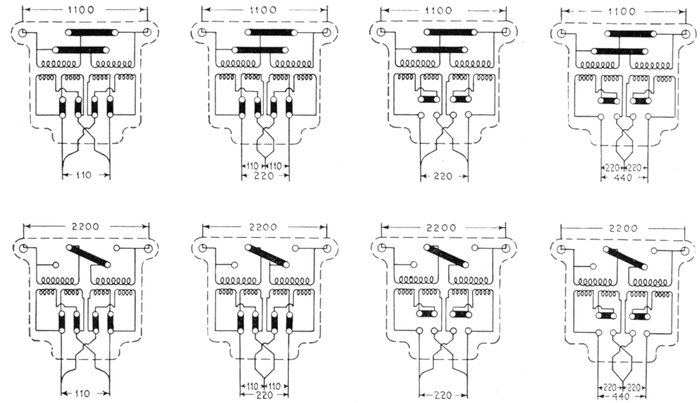
Figs. 2,004 to 2,011.—Connections of standard transformers. All stock transformers are wound for some standard transformation
ratio, such as 10 to 1, but various leads are brought out by means of which ratios of 5, 10 and 20 to 1 may be
obtained for one transformer. The figures show the voltage combinations possible with a standard transformer.
Ques. How are transformers connected for four wire
three phase distribution?
Ans. When the secondaries of three transformers are star
[Pg 1443]connected, a fourth
wire may be run from
the neutral point,
thus obtaining the
four wire system.
Fig. 2,012.—Method of determining core loss. Connect voltmeter and wattmeter as shown in the illustration to the low tension
side of the transformer. By means of a variable voltage transformer bring the applied voltage to the point for which the
transformer is designed. The wattmeter indicates directly the core loss, which includes a very small loss due to the current
in the copper.
Cautions.—1. Make sure of the voltage and frequency. The manufacturers' tabulated statements refer to a definite
voltage and frequency and these have a decided influence upon the core loss. 2. The high tension circuit must remain open
during the test.
The voltage between
any main wire and the
neutral will be 57 per
cent. of the voltage
between any two main
wires. For general distribution
this system
is desirable, requiring
less copper and greater
flexibility than other
systems.
Three phase 200
volt motors may be
supplied from the
main wires and 115
volt lamps connected
between each of the
three main wires and
the neutral; if the
lamp load be very
nearly balanced the
current flowing in the
neutral wire will be
very small, as in the
case of the ordinary
three wire direct current
system.
How to Test
Transformers.—The
troubles incident
to gas or water service
have their parallels
in electric
power distribution.
[Pg 1444]
Fig. 2,013.—Method of determining copper loss. Connect ammeter and wattmeter to high tension side of transformer short
circuit secondary leads, as shown in the illustration, and by means of a variable voltage, adjust current to the full load value for
which the transformer is intended. The wattmeter reading shows the copper loss at full load. The full load primary
current of any transformer is found from the following equation.
- full load current = full load watts ÷ primary volts
EXAMPLE: To find proper full load current on a five kw. 2,200 volt transformer, divide 5,000 watts by 2,200 volts, the
full load current will then be 2.27 amperes. A slight variation in primary current greatly increases or decreases the copper loss.
Remarks.—Copper loss increases with temperature because the resistance of the metal rises. Do not overload the current
coil of the wattmeter. For greater accuracy the I2R drop of potential method should be used.
Companies engaged
in the former, credit
a large percentage
of their losses to
leaky valves and
defective mains.
The remedy may
involve heavy expense
and the loss
is often tolerated
as the lesser of
two evils.
In electric power
distribution the
transformer takes
in part the place of
the valve and pipe
system. An inferior
or defective
transformer usually
treats both
the central station
and its customers
badly, being in this
respect more impartial
than the gas
or water pipe which
may annoy but one
of the interested
parties at a time.
Like a neglected
or defective gas fixture
a transformer
can menace life, failing,
however, to give
the warning the
former gives,
and with a
more hidden
threat on account
of its
location.
[Pg 1445]
Fig. 2,014.—Diagram of connections for regulation test. Connect transformer under test to high tension supply circuit. A
second transformer with same or other known change ratio is also to be connected up, as illustrated. By means of a double
pole double throw switch, the voltmeter can be made to read the pressure on the secondary of either transformer. Supposing
the same change ratio it is evident that if both remain unloaded the voltmeter will indicate the same pressure. A gradually
increasing lamp load up to the limit of the transformer capacity, will be attended by a drop in pressure at the terminals.
This drop can be read as the difference of the voltmeter indications, and when expressed in per cent. of secondary voltage
stands for "regulation." Remarks: The auxiliary transformer is necessary in order to make sure of the high tension line
voltage. A large transformer under test may cause primary drop in taking power. This must be set down against it in testing
regulation. The second transformer gives notice of such drop, whatever be the cause. Figs. 2,012 to 2,014 used by
courtesy of the Moloney Electric Co.
Apart from
this, corresponding
to an
exasperated
customer who
complains at
home and to his
friends of dim
lamps, blackened
lamps, you
will find in the
power station
the manager,
who, also worried
and in no
better humor,
contemplates
the difference
in meter readings
at the end
of the line.
His business
does not increase
and
would not increase
even if
he could lower
the rates, which
he cannot do
because of these
meter readings.
He may be
confident of his
engines and
generators, and
that his line is
up and all right,
but he very seldom
knows
what the transformers
are doing
on top of[Pg 1446]
the poles. Perhaps he feels that
this waste is so slight that it
makes no material difference.
This can be readily ascertained
by means of a set of testing instruments.
Perhaps the transformers
were purchased because of
their attractive prices and
never tested.
Water, plumbing, gas and
steam fittings are subjected
to test. Why not transformers?
Even more so because
transformers take constant
toll from the company
installing them, while gas
and water fittings, once
passed, are off the contractor's
hands.
The busy manager has little
time for complicated treatises
and monographs on electrical
measurements and even handbooks
confront him with
forbidding formulæ. Accordingly
the methods of transformer
testing, which are very
simple, are illustrated in the
accompanying cuts. Managers
of electric power and
lighting companies should
study them carefully.

Fig. 2,015.—Wagner central station core type transformer repair unit consisting of one half set of primary and secondary windings together
with the section of the iron core upon which the coils are wound.
[Pg 1447]
An ammeter, voltmeter and wattmeter are required to make
the tests. Losses are small in good transformers and hence the
instruments should be accurate. For the same reason instruments
should be chosen of the proper capacity to give their
best readings. If there be any doubt about the testing instruments
being correct, they should be calibrated before being
used. The testing circuits should be properly fused for the
protection of the instruments. It is hardly logical, but a very
common practice is to mistrust meters and to watch them closely,
while the transformers are guilty of theft unchallenged, and
keep busily at it on a large scale.
Fig. 2,016.—Moloney tubular air draft oil filled transformer. The case is made of cast iron,
with large steel tubes passing from the bottom through the top. In operation the air in
the tubes becomes hot and expands; a draft is thus produced which carries away considerable
heat.
[Pg 1448]
Transformer Operation with Grounded Secondary.—The
operation of a transformer with a grounded secondary has
been approved by the American Institute of Electrical Engineers,
and by the National Board of Fire Underwriters.
This method of operation effectually prevents a high voltage
occurring upon the low tension wires in case of a breakdown or
other electrical connections occurring between the primary and
secondary windings.
Fig. 2,017.—Moloney pressure transformer adapted for switchboard work in connection with
voltmeters, wattmeters the, etc., in sizes from 25 to 500 watts.
In case of a breakdown without the secondary grounded,
any one touching a part of the low tension system, such as a
lamp socket, might receive the full high pressure voltage. With
the low tension grounded, the fuse in the high tension circuit
will blow and the fault be discovered upon replacing it.
[Pg 1449]
Transformer Capacity for Motors.—The voltage regulation
of a well designed transformer is within 3 per cent. of its rated
voltage on a non-inductive load such as incandescent lamps,
but when motors are connected to the circuit their self-induction
causes a loss of 5 per cent. or more, and if the load be fluctuating,
it is better to use independent transformers for the motor, which
will prevent considerable fluctuations in the incandescent lamps.
Arc lamps do not show slight voltage changes as much as incandescent
lamps. The proper rating of transformers for two
phase and three phase induction motors is given in table on
the next page.
Fig. 2,018.—Moloney current transformer switchboard or indoor type. It is used ordinarily
for insulating an ammeter, a current relay, the current coil of a watt meter or watt hour
meter from a high tension circuit, for reducing the line current to a value suitable for
these instruments.
A three phase induction motor may be operated from three
single phase transformers or one three phase transformer. While
the one three phase transformer greatly reduces the space and
simplifies the wiring, the use of three single phase transformers[Pg 1450]
is more flexible and, in case one transformer burns out, the connection
can be readily changed so that two transformers will
operate the motor at reduced load until the burned out transformer
is replaced or repaired.

Fig. 2,019.—Diagram showing a method of operating a three phase motor on a two phase
circuit, using a transformer having a tap made in the middle of the secondary winding,
so as to get the necessary additional phase. While this does not give a true balanced
three phase secondary, it is close enough for motor work. In the above arrangement, the
main transformer supplies 54 per cent. of the current and the other with the split winding
46 per cent.
It is well to allow one kilowatt per horse power of the motor in
selecting the size for the transformers, excepting in the small
sizes when a little larger kilowatt rating is found to be the most
desirable.
Transformers for Two and Three Phase Motors
| Delivered voltage of circuit |
Single phase transformer voltages |
| 110 volt motor |
220 volt motor |
| Primary |
Secondary |
Primary |
Secondary |
| 1,100 |
1,100 |
122 |
1,100 |
244 |
| 2,200 |
2,200 |
122 |
2,200 |
244 |
Very small transformers should not be used, even when the
motor is large compared to the work it has to do, as the heavy
starting current may burn them out.
The following tables give the proper sizes of transformer for
three types of induction motor and the approximate current
taken by three phase induction motors at 220 volts.
[Pg 1451]
Capacities of Transformers for Induction Motors
| Size of motor horse power |
Kilowatts per transformer |
| Two single phase transformers |
Three single phase transformers |
One three phase transformers |
| 1 |
0.6 |
0.6 |
|
| 2 |
1.5 |
1.0 |
2.0 |
| 3 |
2.0 |
1.5 |
3.0 |
| 5 |
3.0 |
2.0 |
5.0 |
| 7 |
4.0 |
3.0 |
7.5 |
| 10 |
5.0 |
4.0 |
10.0 |
| 15 |
7.5 |
5.0 |
15.0 |
| 20 |
10.0 |
7.5 |
20.0 |
| 30 |
15.0 |
10.0 |
30.0 |
| 50 |
25.0 |
15.0 |
50.0 |
| 75 |
40.0 |
25.0 |
75.0 |
| 100 |
50.0 |
30.0 |
100.0 |
Current taken by Three Phase Induction Motors at 220 Volts
| Horse power of motor |
Approximate full load current |
Horse power of motor |
Approximate full load current |
| 1 |
3.2 |
20 |
50. |
| 2 |
6.0 |
30 |
75. |
| 3 |
9.0 |
50 |
125. |
| 5 |
14.0 |
75 |
185. |
| 10 |
27.0 |
100 |
250. |
| 15 |
40.0 |
150 |
370. |
Transformer Connections for Motors.—Fig. 2,020 shows
the connection of a three phase so called delta connected transformer
with the three primaries connected to the lines leading
from the alternator and the three secondaries leading to the
motor.
The connections for a three phase motor using two transformers
is shown in fig. 2,021 and is identical with the previous[Pg 1452]
arrangement, except that one transformer is left out and the
other two made correspondingly larger.
The copper required in any three wire three phase circuit for
a given power and loss is 75 per cent. that necessary with the
two wire single phase or four wire two phase system having the
same voltage between lines.

Fig. 2,020.—Three phase motor transformer connections; the so-called Delta connected
transformers.
The connections of three transformers for a low tension
system of distribution by the four wire three phase system are
shown in fig. 2,022. The three transformers have their primaries
joined in delta connection and the secondaries in "Y" connection.
The three upper lines of the secondary are the three
main three phase lines, and the lowest line is the common neutral.

Fig. 2,021.—Three phase motor connections using two transformers.
The voltage across the main conductors is 200 volts, while that
between either of them and the neutral is 115 volts; 200 volt motors
should be joined to the mains while 115 volt lamps are connected
between the mains and neutral. The arrangement is similar to the[Pg 1453]
Edison three wire system and the neutral carries current only when the
lamp load is unbalanced.
The voltage between the mains should be used in calculating the
size of wires, and the size of the neutral wire should be made in proportion
to each of the main conductors that the lighting load is to the
total load.

Fig. 2,022.—Delta-star connection of three transformers for low pressure, three phase, four
wire system.
When lights only are used the neutral should be the same as the
main conductors. The copper required in such a system for a given
power and loss is about 33.3 per cent. as compared with a two wire single
phase system or a four wire two phase system using the same voltage.

Fig. 2,023.—Diagram of transformer connections for motors on the monocyclic system.
Monocyclic Motor System.—Motors on the monocyclic
system are operated from two transformers connected as shown
in fig. 2,023. In the monocyclic system the single phase current
is used to supply the lighting load and two wires only are necessary,
but if a self-starting induction motor be required, a third
or teaser wire is brought to the motor and two transformers used.
[Pg 1454]
The teaser wire supplies the quarter phase current required
to start the motor, which afterwards runs as a single phase
synchronous motor and little or no current flows through
the teaser circuit as long as the motor keeps in synchronism;
in case it fall behind, the teaser current tends to bring it up
to speed instead of the motor stopping, as would be the case
of a single phase motor.
Fig. 2,024.—Moloney flaming auto type arc lamp transformer for 110 volts primary to 55
volts secondary. A hook in bottom of case provides means for suspension of lamp. The
transformer may be operated on circuits from 100 to 120 volts primary, 50 to 60 volts
secondary. The secondary capacity is 8 to 12 amperes.
The voltage of the transformers should be tested by means of
a voltmeter or two incandescent lamps joined in series, before
starting up the motor, to see if the proper transformer connections
have been made and prevent an excessive flow of current.
If one of the transformers be reversed the voltage will be almost
doubled; in fact, it is a good plan to check up all the transformer connections
with the voltmeter or lamps which will often save a burn out.
[Pg 1455]
| Arrangement of links on the connecting board |
Primary coils will be connected in |
For circuit voltage normal at |
Ratio of transformation at no load |
| with secondary coils in multiple |
with secondary coils in series. |
| Figs. 2,025 to
2,029.—Diagrams of Wagner transformer connection board,
and table showing various arrangements of the terminal
links, corresponding transformation ratios, and suitable
primary voltages.[Pg 1456] |
 |
Multiple |
1,100 |
10:1 |
5:1 |
 |
Multiple |
1,100 |
9.05:1 |
4.52:1 |
 |
Series |
2,200 |
20:1 |
10:1 |
 |
Series |
2,200 |
19.05:1 |
9.5:1 |
 |
Series |
2,200 |
18.1:1 |
9.05:1 |
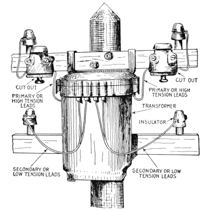
Fig. 2,030.—Installation of a transformer on pole; view showing method of attachment and
disposition of the primary and secondary leads, cutouts, etc.

Fig. 2,031.—Diagram of static booster or regulating transformer. It is used for regulating
the pressure on feeders. In the figure, B are the station bus bars, R the regulable transformer,
F the two wire feeders, and T a distant transformer feeding into the low pressure
three wire distributing network N. The two ends of the primary, and one end of the
secondary of R, are connected to the bus bars as shown. The other end of the secondary,
as well as a number of intermediate points, are joined up to a multiple way switch S,
to which one of the feeder conductors is attached, the other feeder main being connected
to the opposite bus bar. As will be evident from the figure, by manipulating S extra
volts may be added to the bus bar pressure at will, and the drop along F compensated for.
R is a step transformer, the total secondary difference of pressure being comparatively
small. The above device possesses rather serious drawbacks, in that the switch S has
to carry the main current, and that the supply would be stopped if the switch got out of
order. Kapp improved on the arrangement by putting the switch in the primary circuit.
[Pg 1457]
CHAPTER LIII
CONVERTERS
The alternating current must change to a direct current in
many cases as in railroad work because the induction motor is
not so satisfactory as the direct current series motor and the
alternating current series motor is slow in coming into general use.
In all kinds of electrolytic work, transformation must be made,
and in many cities where the direct current system was started,
it is still continued for local distribution, but the large main
stations generating alternating currents and frequently located
some distance away from the center of distribution have replaced
a number of small central stations.
Transformation may be made by any of the following methods:
- 1. Rotary converters;
- 2. Motor generator sets;
- 3. [A]Mercury vapor rectifiers;
- 4. [9]Electrolytic rectifiers.
Strictly speaking, a converter is a revolving apparatus for converting
alternating current into direct current or vice versa; it is
usually called a rotary converter and is to be distinguished from
the other methods mentioned above.
Broadly, however, a converter may be considered as any
species of apparatus for changing electrical energy from one form
into another.
[Pg 1458]
According to the standardization rules of the A. I. E. E.
converters may be classified as:
- 1. Direct current converters;
- 2. Synchronous converters;
- 3. Motor converters;
- 4. Frequency converters;
- 5. Rotary phase converters.
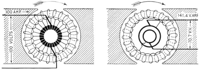
Figs. 2,032 and 2,033.—Gramme ring dynamo and alternator armatures illustrating converter
operation. The current generated by the dynamo is assumed to be 100 amperes. Now,
suppose, an armature similar to fig. 2,032 to be revolving in a similar field, but let its windings
be connected at two diametrically opposite points to two slip rings on the axis, as in
fig. 2,032. If driven by power, it will generate an alternating current. As the maximum
voltage between the points that are connected to the slip rings will be 100 volts,
and the virtual volts (as measured by a voltmeter) between the rings will be 70.7 (= 100
÷ √2), if the power applied in turning this armature is to be 10 kilowatts, and if the circuit
be non-inductive, the output in virtual amperes will be 10,000 ÷ 70.7 = 141.4. If the
resistances of each of the armatures be negligibly small, and if there be no frictional or
other losses, the power given out by the armature which serves as motor will just suffice
to drive the armature which serves as generator. If both armatures be mounted on the
same shaft and placed in equal fields, the combination is a motor dynamo. In actual machines
the various losses are met by an increase of current to the motor. Since the armatures
are identical, and as the similarly placed windings are passed through identical magnetic
fields, one winding with proper connections to the slip rings and commutator will do
for both. In this case only one field is needed; such a machine is called a converter.
A direct current converter converts from a direct current to a
direct current.
A synchronous converter (commonly called a rotary converter)
converts from an alternating current to a direct current.
A motor converter is a combination of an induction motor with a
synchronous converter, the secondary of the former feeding the armature
of the latter with current at some frequency other than the impressed
frequency; that is, it is a synchronous converter in combination
with an induction motor.
[Pg 1459]
A Frequency Converter (preferably called a frequency changer)
converts alternating current at one frequency into alternating current
of another frequency with or without a change in the number of phases
or voltages.
A Rotary Phase Converter changes alternating current of one or
more phases into alternating current of a different number of phases,
but of the same frequency.
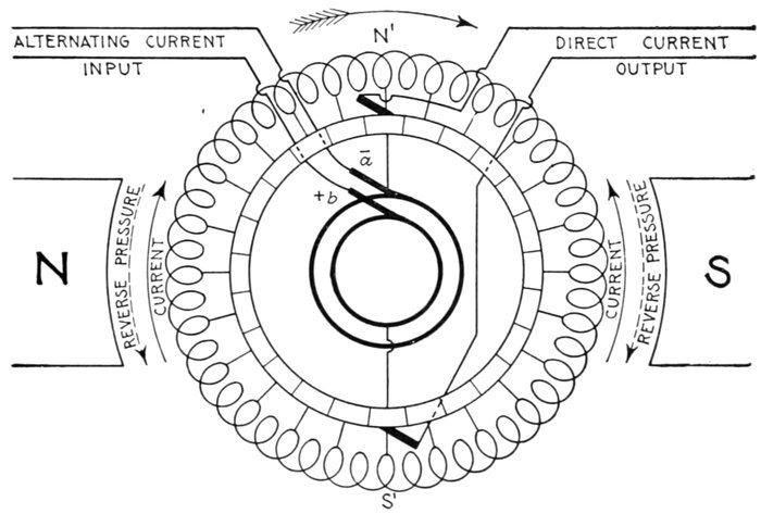
Fig. 2,034.—Diagram of ring wound single phase rotary converter. It is a combination of a
synchronous motor and a dynamo. The winding is connected to the commutators in
the usual way, and divided into two halves by leads connecting segments 180° apart
to collector rings. A bipolar field is shown for simplicity; in practice the field is multipolar
and energized by direct current.
Rotary Converters.—The synchronous or rotary converter
consists of a synchronous motor and a direct current generator
combined in one machine. It resembles a direct current generator
with an unusually large commutator and an auxiliary
set of collector rings.
[Pg 1460]
Ques. In general, how does a rotary converter operate?
Ans. On the collector ring side it operates as a synchronous
motor, while on the commutator side, as a dynamo.
Its design in certain respects is a compromise between alternating
current and direct current practice most noticeably with respect to the
number of poles and speed.
Ques. Upon what does the speed depend?
Ans. Since the input side consists of a synchronous motor,
the speed is governed by the frequency of the alternating current
supplied, and the number of poles.
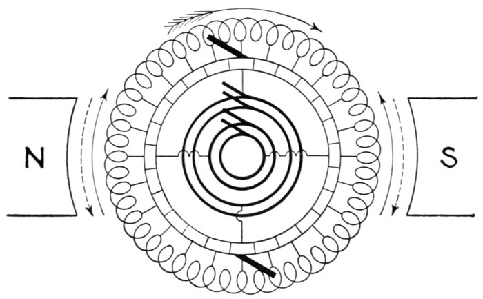
Fig. 2,035.—Diagram of two phase rotary converter. This is identical with the single phase
machine with the exception that another pair of collector rings are added, and connected
to points on the winding at right angles to the first, giving four brushes on the alternating
side for the two phase current. The pressure will be the same for each phase as in
the single phase rotary. Neglecting losses the current for each phase will be equal to
the direct current × 1 ÷ / √2 = direct current × .707.
Fig. 2,034 is a diagram of a ring wound rotary converter. This style
winding is shown to simplify the explanation. In practice drum wound
armatures are used, the operation, however, is the same.
[Pg 1461]
With this simple machine the following principles can be demonstrated:
1. If the coil be rotated, alternating currents can be taken from the
collector rings and it is called an alternator.
2. By connecting up the wires from the commutator segments, a
direct current will flow in the external circuit making a dynamo.
3. Two separate currents can be taken from the armature, one supplying
alternating current and the other direct current; such a machine is
called a double current generator.
4. If a direct current be sent in the armature coil through the commutator,
the coil will begin to rotate as in a motor and an alternating
current can be taken out of the collector rings. Such an arrangement
is called an inverted rotary converter.
5. If the machine be brought up to synchronous speed by external
means and then supplied with alternating current at the collector rings,
then if the direction of the current through the armature coil and the
pole piece have the proper magnetic relation, the coil will continue to
rotate in synchronism with the current. A direct current can be taken
from the commutator, and when used thus, the machine is called simply
a rotary converter.
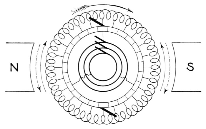
Fig. 2,036.—Diagram of three phase rotary converter. In this type, the winding is tapped at
three points 120° distant from each other, and leads connected with the corresponding
commutator segments.
[Pg 1462]
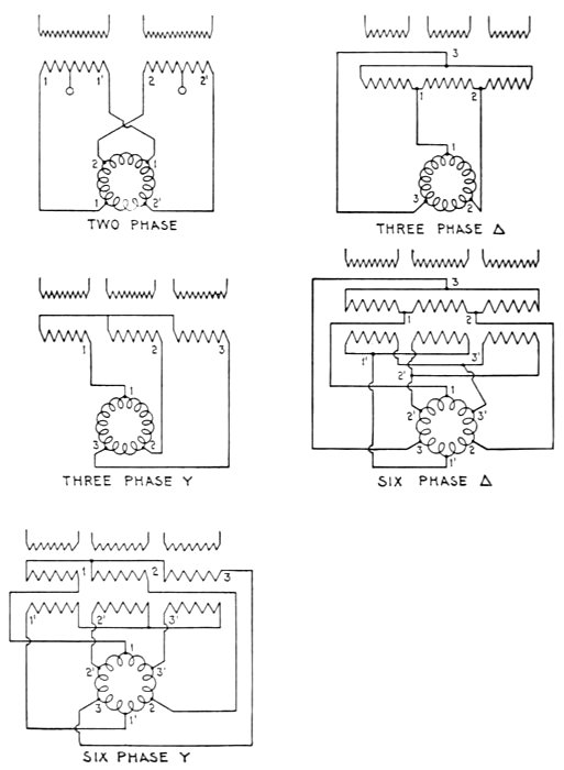
Figs. 2,037 to 2,041.—Various
rotary converter and transformer
connections. Fig. 2,037 two
phase connections; fig. 2,038
three phase delta connections;
fig. 2,039 three phase Y or star
connections; fig. 2,040 six phase
delta connections; fig. 2,041 six
phase Y connections.
[Pg 1463]
Ques. What is the relation between the impressed
alternating pressure and the direct pressure at the commutator?
Ans. The ratio between the impressed alternating pressure
and the direct current pressure given out is theoretically constant,
therefore, the direct pressure will always be as 1 to .707 for
single phase converters or if the pressure of the machine used
above indicate 100 volts at the direct current end, it will indicate
70.7 volts at the alternating current side of the circuit.
Ques. Name two different classes of converter.
Ans. Single phase and polyphase.
Ques. What is the advantage of polyphase converters?
Ans. In the majority of cases two or three phase converters
are used on account of economy of copper in the transmission
line.
Ques. How is the armature of a polyphase converter
connected?
Ans. Similar to that of an alternator with either delta or
Y connections.
Figs. 2,037 to 2,041 show various converter connections between the
collector rings and commutator.
Fig. 2,037 indicates how the armature is tapped for two phase connections.
Fig. 2,038 shows three phase delta connections, and fig. 2,039 the
three phase Y or star connections.
Six phase delta and Y connections are frequently used as shown in
fig. 2,040 and fig. 2,041, both of which require two secondary coils in
the transformer, one set of which is reversed, so as to supply the current
in the proper direction.
Ques. With respect to the wave, what is the relation
between the direct and alternating pressures?
Ans. The direct current voltage will be equal to the crest
of the pressure wave while the alternating voltage will depend[Pg 1464]
on the virtual value of the maximum voltage of the wave according
to the connections employed.
Table of Alternating Current and Voltage in Terms of Direct Current
(According to Steinmetz)
|
DIRECT CURRENT |
SINGLE PHASE |
TWO PHASE |
THREE PHASE |
SIX PHASE |
TWELVE PHASE |
n PHASE |
| VOLTS BETWEEN COLLECTOR RING AND NEUTRAL POINT |
1 |
1 / (2√2) = .354 |
1 / (2√2) = .354 |
1 / (2√2) = .354 |
1 / (2√2) = .354 |
1 / (2√2) = .354 |
1 / (2√2) = .354 |
| VOLTS BETWEEN ADJACENT COLLECTOR RINGS |
1 |
1 / √2 = .707 |
½ = .5 |
√3 / (2√2) = .612 |
1 / (2√2) = .354 |
.183 |
(SIN(π / n)) / √2 |
| AMPERES PER LINE |
1 |
√2 = 1.414 |
1 / √2 = .707 |
(2√2) / 3 = .943 |
√2 / 3 = .472 |
.236 |
(2√2) / n |
| AMPERES BETWEEN ADJACENT LINES |
1 |
√2 = 1.414 |
½ = .5 |
(2√2) / (3√3) = .545 |
√2 / 3 = .472 |
.455 |
(√2SIN(π / n)) / n |
[Pg 1465]
In a single phase rotary, the value of the direct pressure is 1 to .707,
therefore a rotary which must supply 600 volts direct current must be
supplied by 600 × .707 = 424 volts alternating current. For three phase
rotaries the ratio is 1 to .612, or in order to produce 600 volts direct
current, 600 × .612 = 367 volts on the alternating current side of the
rotary is required.

Fig. 2,042.—Westinghouse rotary converter armature coils. These are wound from bar
copper and are interchangeable. The armature coils are heavily insulated to withstand
the tests specified in the standardization rules of the American Institute of Electrical
Engineers.
Fig. 2,034 shows a complete diagram of the electrical connections.
A single phase rotary is illustrated so as to simplify the wiring.
The table of Steinmetz on page 1,464 gives the values of the alternating
volts and amperes in units of direct current.
Ques. How is the voltage of a rotary varied on the
direct current side?
Ans. Pressure or potential regulators are put in the high
tension alternating current circuit and may be regulated by small
motors operated from the main switchboard or operated by hand.
[Pg 1466]
Ques. What is the advantage of unity power factor for
rotary converters?
Ans. It prevents overheating when the rotary is delivering
its full load in watts.
Ques. What greatly influences the power factor of the
high tension line?
Ans. The strength of the magnetic field.
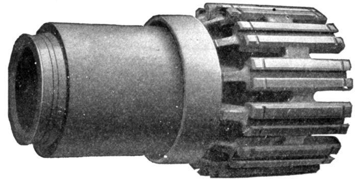
Fig. 2,043.—Westinghouse rotary converter armature spider. It is made of cast iron or cast
steel. The dovetail grooves are machined in the feet or ends of the arms and in these
slots the laminations forming the armature coil engage.
Ques. Does variation of the field strength materially
affect the voltage?
Ans. No.
Since variation of the field strength does not materially affect the
voltage, by adjusting the resistance in series with the magnetic circuit,
the strength of the field can be changed and the power factor kept 1
or nearly 1 as different loads are thrown on and off the rotary.
Ques. What is the effect of a field too strong or too
weak?
Ans. If too strong, a leading current is produced, and if too[Pg 1467]
weak, the current lags, both of which reduce the power factor
and are objectionable.
Usually there is a power factor meter connected up in the main generating
station and one also in the rotary substation, and it is the duty of
the attendant at the substation to maintain the proper power factor.
Ques. What is the ordinary range of sizes of rotaries?
Ans. From 3 kw. to 3,000 kw.
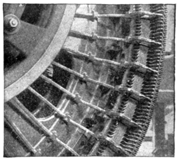
Fig. 2,044.—Equalizer connections of Westinghouse rotary converter. The armature coils
are cross connected at points of equal voltage and taps are led out from the winding at
suitable points to the slip rings. This construction insures a uniform armature saturation
below each pole piece and eliminates one cause of sparking at the commutator.
Ques. What is the general construction of a rotary
converter?
Ans. It is built similar to a dynamo with the addition of
suitable collector rings connected to the armature windings at
points having the proper phase relations.
Standard rotary converters have been developed for 25 and 60 cycles.
The standard railway machines are compound wound, the series field
being designed for a compounding of 600 volts at no load and full load
when supplied from a source of constant pressure with not more than 10
per cent. resistance drop and with 20 to 30 per cent. reactance in the circuit.
The large size machines are usually wound for six phase operation.
[Pg 1468]
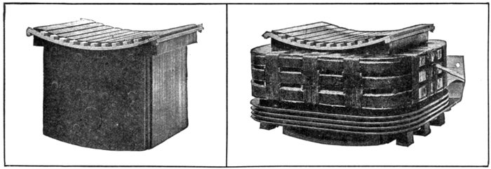
Figs. 2,045 and 2,046.—Westinghouse pole construction for converters. Fig. 2,045, pole without windings; fig 2,046, pole with
windings. Poles are built up of steel laminations held together with rivets. Projections on the inner ends of the poles
form seats for the field coils and hold them in position. Copper dampers set in slots in the pole faces insure stable operation.
Rotary converters for railway service are almost invariably compound wound. The series windings are formed
of bare copper strap. The shunt windings are of insulated copper strap or wire. Spaces between coil turns and sections
are provided for ventilation.
Compounding of
Rotary Converters.—Compounding
is desirable
where the load
is variable, such as is
the case with interurban
railway systems.
The purpose of
the compounding is to
compensate automatically
for the drop due
to line, transformer,
and converter impedance.
On account of the
low power factor
caused by over compounding,
and the
fact that substations
are customarily connected
to the trolley
at its nearest point
without feeder resistance,
over compounding
is not
recommended. An
adjustable shunt to
the series field is
provided with each
machine.
Shunt wound converters
are satisfactory
for substations in[Pg 1469]
large cities and similar installations where due to the larger
number of car units demanding power, the load is more nearly
constant.
Ratio of Conversion.—The relation between the alternating
and direct current voltages varies slightly in different machines,
due to differences in design. The best operating conditions
exist when the desired direct current voltage is obtained with
unity power factor at the converter terminals when loaded.
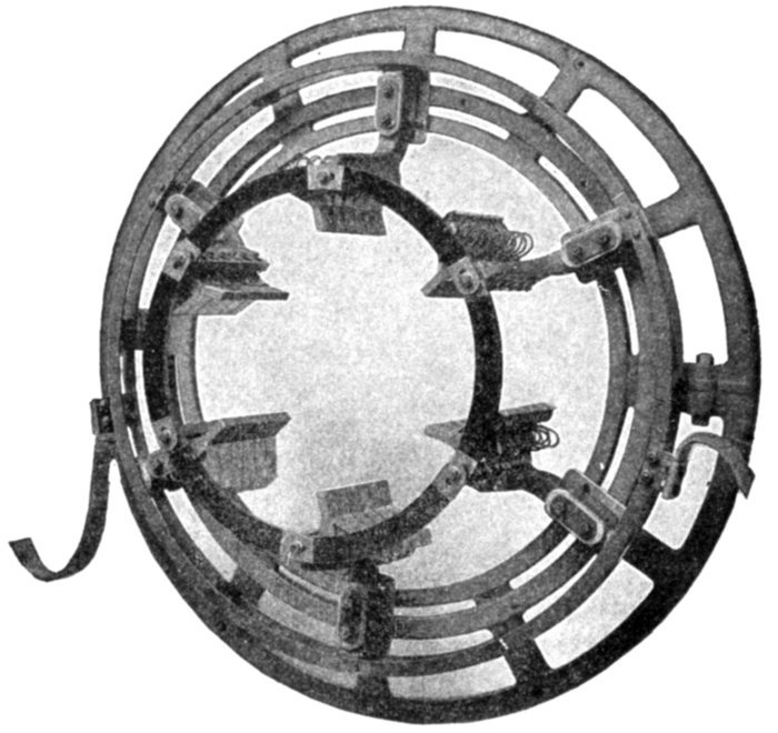
Fig. 2,047.—Westinghouse rotary converter brush rigging showing method of bracing the
brushes. The brushes are supported by a rigid cast iron rocker ring which fits accurately
in the frame. A handwheel worm and screw arrangement for shifting the brushes is
provided. Cast iron arms bolted to, but insulated from the rings, carry the rods on which
the brush holders are mounted. Brush holders are of brass cast in one piece, of the sliding
type and have braided copper shunts. Brush tension is adjustable.
[Pg 1470]
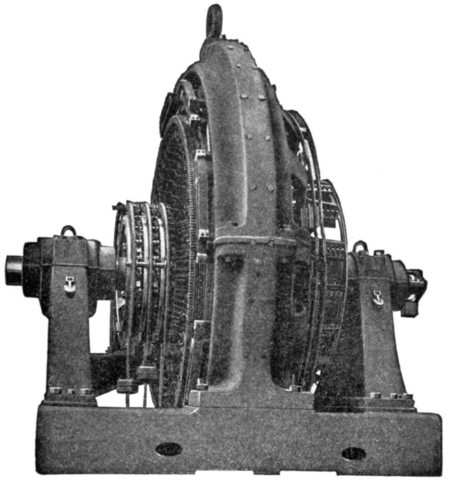
Fig. 2,048.—Westinghouse commutating pole rotary converter. The construction details
are substantially the same as for the railway converter, with exception of the commutating
poles. The application of commutating pole converters is particularly desirable where
special requirements such as great overload capacity or large capacity and low voltage
enable them to show to the greatest advantage. Commutating poles as applied to rotary
converters fulfill the same functions as in the more familiar applications to dynamos and
motors. That is, the commutating pole insures sparkless commutation from no load
to heavy overloads with a fixed brush position. Brush shifting devices are not furnished
on commutating pole converters. Commutating pole rotary converters for railway
service are normally arranged for automatic compounding which is effected by the proper
combination of series excitation and inductance between the generator and the rotary
converter. This inductance is normally included in the transformer but in special cases
may be partly in a transformer and partly in a separate reactance. It is possible to produce
by this means a slight increase in the direct current voltage provided the voltage
drop in the alternating current line be not excessive. Usually it is so arranged that the
compounding that can be obtained is just sufficient to overcome the alternating current
line voltage drop. The standard Westinghouse method of starting is alternating current
self-starting. With this method of self-starting, the brushes of a commutating pole rotary
converter must be lifted from the commutator during the starting operation to prevent
sparking. A mechanical device, as shown in fig. 2,050, is provided which accomplishes
this. With direct current or motor starting a brush lifting device is not necessary.
[Pg 1471]
Ques. Upon what does the ratio of conversion depend?
Ans. Upon the number of phases and method of connecting
the windings.
For single phase or two phase machines it is 1 to .7; for three phase,
1 to .612, or six phase, 1 to .7 or 1 to .613 depending upon the kind
of connection used for the transformer.
For example, a two phase rotary receiving alternating current at 426
volts will deliver direct current at 600 volts, while a three phase rotary
receiving alternating current at 367 volts will deliver direct current at
600 volts.
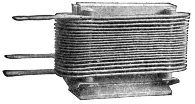
Fig. 2,049.—Commutating pole of Westinghouse commutating pole rotary converter. The
commutating poles are similar in general construction to the main poles. The coils are
of bare copper strap wound on edge. Ventilating spaces are provided between the pole
and coil and between turns. The copper winding is bare except for a few turns at each
end. Insulating bolts retain the turns in their proper position.
Ques. What difficulty would be encountered if other
ratios of conversion than those given above were required?
Ans. An armature with a single winding could not be used.
It would be necessary to use a machine with two distinct armature
windings or else a motor generator set.
Ques. What change in voltage is necessary between a
converter and the alternator which furnishes the current?
Ans. The voltage must be reduced to the proper value by a
step down transformer.
[Pg 1472]
Voltage Regulation.—As the ratio of the alternating to the
direct current voltage of a converter is practically constant,
means must be provided to compensate for voltage variation
due to changes of load in order to maintain the direct current
pressure constant.
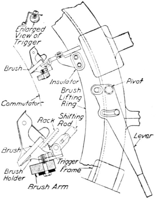
Fig. 2,050.—Westinghouse brush lifting device for commutating pole rotary converter. A
rack is attached to each brush as shown. Into this rack the spring hinged lifting hook
of the raising device engages only when the lifting lever is shifted toward the raised position.
The lifting arrangement is independent of the brushes during normal running,
so it can in no way affect the operation of the machine. Each brush is merely raised and
lowered within its own holder so the brush position or commutation is not altered.
There are several methods of doing this, as by:
- 1. Shifting the brushes (objectionable);
- 2. Split pole method;
- 3. Regulating pole method;
- 4. Reactance method;
- 5. "Multi-tap" transformer method;
- 6. Synchronous regulator.
[Pg 1473]
Shifting the Brushes.—Were
it not for the difficulties encountered,
this would be a most convenient
method of voltage
regulation, since by this procedure
the direct current voltage
may be varied from maximum
to zero. It is, however, not
practical because of the excessive
sparking produced when the
brushes are shifted out of the
neutral plane.

Figs. 2,051 to 2,053.—Woodbridge split pole rotary converter. Each pole is split into three sections and provided with windings
as indicated in fig. 2,051. When excited as in fig. 2,052, the commutator voltage is at its highest value; when excited as
in fig. 2,053, the commutator voltage is low. The change in commutator voltage for constant collector ring voltage is in
virtue of the property of rotary converters that the ratio of these two voltages is a function of the width of the pole arc.
Split Pole Method.—In order
to overcome the difficulty encountered
in shifting the brushes
the split pole method was devised
by Woodbridge in which each
field pole is split into two or
three parts.
The effect of this is the same
as shifting the brushes except that
no sparking results.
The other part is arranged so
that its excitation may be varied,
thus shifting the resultant plane
of the field with respect to the
direct current brushes.
One of these parts is permanently
excited and it produces
near its edge the fringe of field
necessary for sparkless commutation.
[Pg 1474]
Regulating Pole Method.—As applied to the rotary converter
regulating poles fulfill the same functions as commutating
or interpoles (see page 385) on motors and dynamos, that is,
they insure sparkless commutation from no load to heavy overloads
with a fixed brush position.
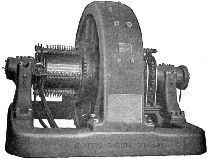
Fig. 2,054.—General Electric regulating pole rotary converter. The field structure is divided
into two parts, a main pole and a regulating pole. The ratio between the voltages on
the direct current and alternating current sides may be readily varied by varying the
excitation of the regulating poles, the only auxiliary apparatus required being a field
rheostat for controlling the exciting current. Where automatic regulation is required,
machines may be provided with compound windings, or automatic field regulators may
be used responsive to either voltage or current. These converters are adapted for a
variety of purposes where a variable conversion ratio is required, either to maintain constant
D. C. voltage with varying A. C. voltage or to vary the D. C. voltage as required.
Converters may be operated inverted where it is required to furnish constant or variable
A. C. voltage from a D. C. source. Where converter and inverted converter operation
are desired, an opposite direction of rotation is required for the inverted operation.
Converters of this type are built in capacities from 300 kw. up to 3,000 kw., and constructed
to give a voltage range between 240 and 300 volts, to cover the usual lighting
circuit requirements. In design, they are similar to standard rotary converters, with
the exception that the regulating poles are located next to the main pole pieces and a
slightly different form of pole piece bridge is used for the main poles, in order to allow
the auxiliary poles to be readily removed or assembled.
[Pg 1475]
The regulating poles are used in order to vary the ratio between
the alternating current collector rings and the direct
current side without the use of auxiliary apparatus such as
induction regulators or dial switches which involve complicated
connections and many additional wires. The regulating poles
are arranged with suitable connection so that the current through
them can be raised, lowered or reversed.

Fig. 2,055.—Detail of Westinghouse commutating pole rotary converter brush, showing rack.
The brush lifting mechanism and its operation is explained in fig. 2,050.
The characteristics of the regulating pole converter being
novel, a detailed explanation of the principles involved is given
to facilitate a clear understanding of its operation.
Consider a machine with a field structure as shown in fig. 2,056 resembling
in appearance a machine with commutating poles, but with
the brushes so set that one of the regulating poles adds its flux to that of
one main pole, cutting the inductors between two direct current
brushes. The regulating pole is shown with a width equal to 20 per cent.
of that of the main pole.
To obtain definite figures, it will be assumed that the machine at
normal speed, with the main poles excited to normal density, but with
no excitation on the regulating poles, gives 250 volts direct current
pressure. Then with each regulating pole excited to the same density[Pg 1476]
as the main poles, and with a polarity corresponding to that of the
main pole in the same section between brushes, the direct current
pressure will rise to 300 volts at the same speed, since the total flux
cutting the inductors in one direction between brushes has been increased
20 per cent.
If, on the other hand, the excitation of the regulating poles be reversed
and increased to the same density as that of the main poles, the direct
current pressure will fall to 200 volts, since in this case the regulating
poles give a reverse pressure, that is, a pressure opposing that generated
by the main poles.
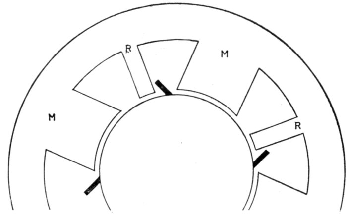
Fig. 2,056.—Diagram of field of regulating pole converter illustrating principles explained in
the accompanying text.
Now, if the machine be equipped with collector rings, that is, if it
be a converter, this method of varying the direct current voltage from
200 to 300 volts does not give nearly as great a variation of the alternating
current voltage; in fact, the latter voltage will be the same when
delivering 200 volts as when delivering 300 volts direct current pressure,
if the field excitation be the same.
This may be seen by reference to fig. 2,057, which is a diagram of the
alternating current voltage developed in the armature windings by the
two sets of poles.[10]
The horizontal line OA represents the alternating current voltage
[Pg 1477]generated by the main poles, alone, with the regulating poles unexcited,
that is, when delivering 250 volts direct current pressure.
For a six phase converter OA measures about 180 volts diametrically,
that is, between electrically opposite collector rings.
If now the regulating poles be excited to full strength, to bring the
direct current pressure up to 300 volts, the alternating current voltage
generated by the regulating poles will be 90 degrees out of phase with
that generated by the main poles (since they are placed midway between
the main poles), and will be about 40 volts as shown by the line AB.
The resultant alternating current volts across the collector rings will
be represented by the line OB with a value equal to 184.
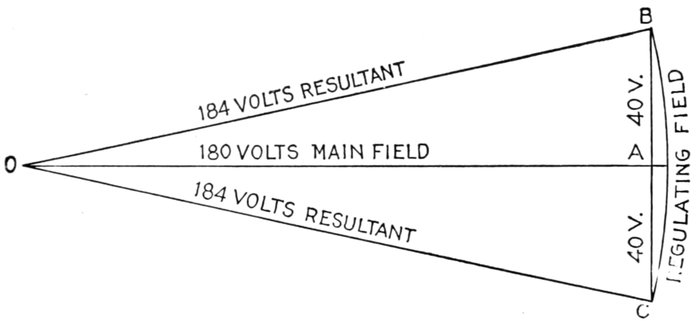
Fig. 2,057.—Voltage diagram for regulating pole converter illustrating principles explained
in the accompanying text.
Again, if the regulating poles be reversed at full strength, to cut the
direct current pressure down to 200 volts, the alternating current voltage
of the main and regulating poles will be OA and AC respectively, giving
the resultant OC equal to OB with a value of 184 volts. Accordingly,
the direct current pressure may be either 200 or 300 volts with the same
alternating current pressure, and if the main field be kept constant,
the direct current pressure may range between 200 or 300 volts, while
the alternating current pressure varies only between 180 and 184 volts.
The alternating current pressure can be kept constant through the
full range of direct current voltage by changing the main field so as
always to give an equal and opposite flux change to that of the regulating
field. A constant total flux may thus be obtained equal to the
radius of the arc BC, fig. 2,057. In this case the line OA, representing
the main field strength, will equal OB when the regulating field is not
excited, and 250 volts can only be obtained at this adjustment.
This method of operation gives unity power factor with a constant
impressed pressure of 184 volts alternating current with a range of direct
current voltage from 200 to 300 volts.
[Pg 1478]
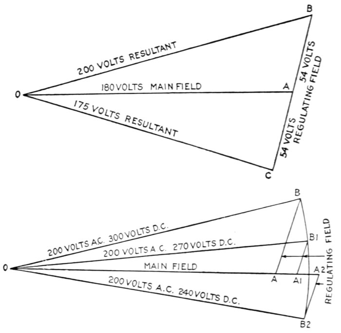
Figs. 2,058 and 2,059.—Diagrams illustrating the effect on the alternating current voltage
due to varying the regulating field strength (of a machine proportioned according to
fig. 2,060), from a density equal to that in the main poles to the same density reversed,
the main field strength remaining constant. The D. C. voltage in this case varies from
30 per cent. above that produced by the main field alone to 30 per cent. below, or from
325 to 175 volts, while the A. C. voltage varies only from 200 to 175 volts. To keep
the A. C. voltage constant with such a machine the main field must be strengthened as
the regulating field is weakened or reversed to reduce the D. C. voltage. This strengthening
increases the core loss particularly on low direct current voltages, which however, are rarely
required, hence a machine proportioned as in fig. 2,060, would not be operated through
so wide a range as 175 to 325 volts. Assume that the range is 240 to 300 volts, and that
at the highest voltage, both main and regulating fields have the same density, presenting to
the armature practically one continuous pole face of uniform flux intensity. The diagram
of A. C. component voltages to give constant A. C. resultant voltage across the
rings for the case, is shown in fig. 2,059. At 300 volts D. C., the main field produces an
A. C. voltage OA, and the regulating field, a voltage AB, with a resultant OB, equal to
about 200 volts A. C. At 270 volts D. C., the main field produces an A. C. voltage OA,
and a regulating field voltage AB, giving a resultant A. C. voltage OB, equal to 200 volts.
Similarly, at 240 volts D. C., the main field produces an A. C. voltage OA, and the regulating
field (now reversed) produces the reverse voltage AB, giving the resultant OB
again equal to 200 volts. It will be noted that, theoretically the main field strength
must be increased about 15 per cent. above its value at 300 volts D. C. in order to keep
the D. C. voltage at 250 volts.
[Pg 1479]
Ques. Where should the regulating poles be located
for best results?
Ans. A better construction is obtained by placing them
closer to the corresponding main pole, as in fig. 2,060, than when
spaced midway between the main poles as in fig. 2,056.
Ques. When the regulating poles are spaced as in fig.
2,060, what is the effect on the direct current voltage?
Ans. The effect is the same as for the midway position
(fig. 2,056) except for magnetic leakage from the main poles to
the regulating poles when the latter is opposed to the former,
that is, when the direct current voltage is being depressed.
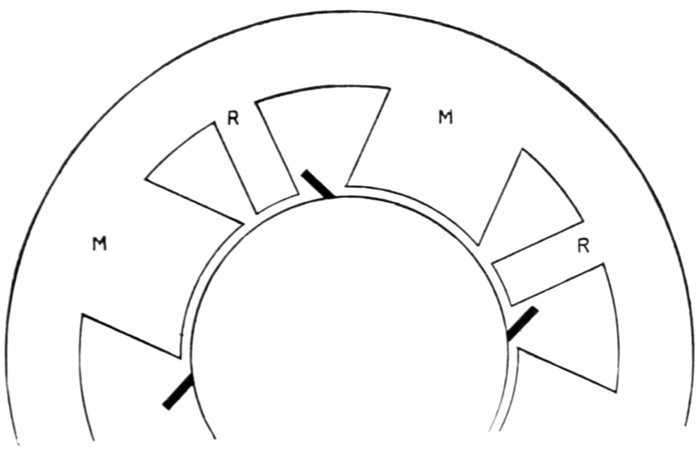
Fig. 2,060.—Diagram illustrating placement of regulating poles. In practice machines are
not built as indicated diagrammatically in fig. 2,056, that is, with regulating poles spaced
midway between the main poles, because a better construction is obtained by placing the
regulating pole closer to the corresponding main pole, as shown above.
Ques. What is the effect on the alternating current
voltage?
Ans. It is somewhat altered as explained in figs. 2,058 and
2,059.
[Pg 1480]
Reactance Method.—This consists in inserting inductance
in the supply circuit and running the load current through a
few turns around the field cores. This method is sometimes
called compounding, and as it is automatic it is generally used
where there is a rapidly fluctuating load.
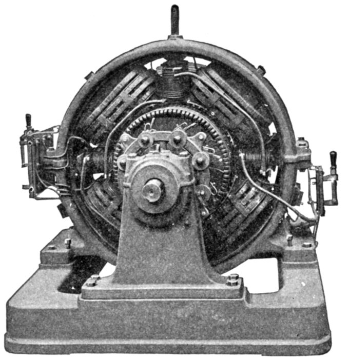
Fig. 2,061.—Westinghouse 300 kw., 1,500 volt, three phase, 25 cycle, commutating pole
rotary converter. The illustration shows clearly the commutating, and main poles and
the relative sizes, also arrangement of the terminal connections.
If a lagging current be passed through an inductance, the
collector ring voltage will be lowered, but will be raised in case
of a leading current. The degree of excitation governs the
change in the phase of the current to the converter, the excitation,
in turn, being regulated by the load current. Accordingly[Pg 1481]
with series inductance, the effect of the series coils on the field
of the converter is quite similar to that of the compounding of
the ordinary railway dynamo.
Multi-tap Transformer Method.—The employment of a
variable ratio step down transformer for voltage regulation is a
non-automatic method of control and, accordingly, is not desirable
except in cases where the load is fairly constant over
considerable periods of time. It requires no special explanation.
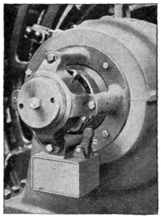
Fig. 2,062.—Mechanical oscillator and speed limit device of Westinghouse commutating pole
rotary converter. It automatically prevents the armature of the converter remaining
in one position and thus not allowing brushes to wear grooves in both commutator and
collector rings. The oscillator is a self-contained device carried at one end of the shaft.
The operating parts consist of a hardened steel ball and a steel plate with a circular ball
race, backed by a spring. The machine is so installed with a slight inclination toward
the end carrying the oscillator. As the armature revolves the ball is carried upward and
owing to the convergence of the steel race and shaft face, the spring is compressed. The
reaction of the spring forces the armature away from its natural position and allows the
ball to drop back to the lowest point of the race.
Synchronous Booster Method.—This consists of combining
with the converter a revolving armature alternator having the
same number of poles.
[Pg 1482]
Ques. How is the winding of the booster alternator
armature connected?
Ans. It is connected in series with the input circuits on the
converter.

Fig. 2,063.—Westinghouse 2,000 kw., 270 volt, direct current, 6 phase, 167 R.P.M., synchronous
booster rotary converter, having a voltage range from 230 to 310 volts. It
consists of a standard rotary converter in combination with a revolving armature alternator
mounted on the same shaft with the rotary converter and having the same number
of poles. By varying the field excitation of the alternator, the alternating current voltage
impressed on the rotary converter can be increased or decreased as desired. The direct
current voltage delivered by the converter is thereby varied accordingly. The principle
of operation of the booster converter is therefore very simple and easily understood. It
is simply a combination of two standard pieces of electrical apparatus, accordingly there
are incorporated in it no details of construction essentially different from those encountered
in standard rotary converters and alternators. The only novelty is in their combination.
The frames may be supported either from the rotary converter frame, as in the small
units, or from the bed plate, as in the larger ones. A synchronous booster converter can
be built, if necessary, with a vertical shaft to satisfy special floor space and head room
requirements.
Ques. How are the field windings connected?
Ans. They are either fed with current regulated by means
of a motor operated field circuit rheostat, or joined in series with
the commutator leads of the converter.
[Pg 1483]
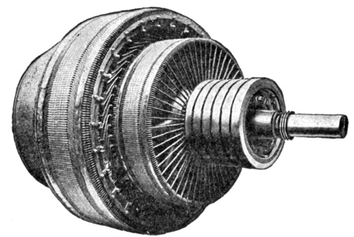
Fig. 2,064.—Armature of Westinghouse synchronous booster converter. Heavy cast yokes
form the frames. They are proportioned to rigidly support the laminated steel field poles.
The poles are fastened to the frame with through bolts. A lifting hook is provided on all
frames. The bed plates are in one piece for the smaller machines but two piece bed plates
are used for the larger ones. The bearings are ring oiling and have babbitt wearing surfaces
that are renewable.
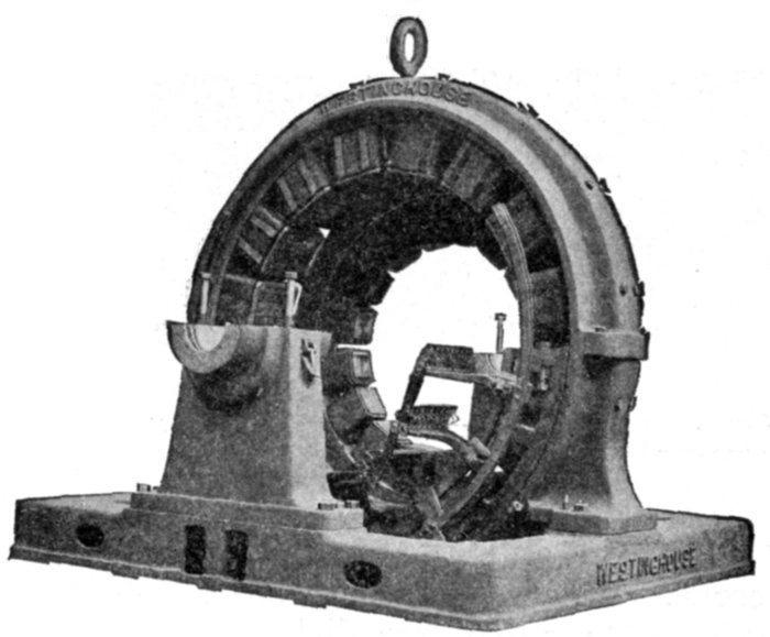
Fig. 2,065.—Westinghouse field frames and bearings for synchronous booster rotary converter.
The frames consist of heavy cast yokes. The poles are fastened to the frames with through
bolts. The bed plate is in one piece for the small machines and in two pieces for the
large ones.
[Pg 1484]
Ques. For what service is the synchronous booster
method desirable?
Ans. For any application where a relatively wide variation
in direct current voltage is necessary.
It is particularly desirable for serving incandescent lighting systems
where considerable voltage variation is required for the compensation
of drop in long feeders, for operation in parallel with storage batteries
and for electrolytic work where extreme variations in voltage are required
by changes in the resistance of the electrolytic cells.
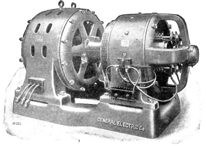
Fig. 2,066.—General Electric motor generator set consisting of 2,300 volt synchronous motor
and 550 volt dynamo.
Motor Generator Sets.—The ordinary rotary converter is
the most economical machine for converting alternating currents
into direct currents, and where slight variations in the direct
current voltage is necessary, they are mostly used on account
of their high efficiency, and because they are compact.
[Pg 1485]
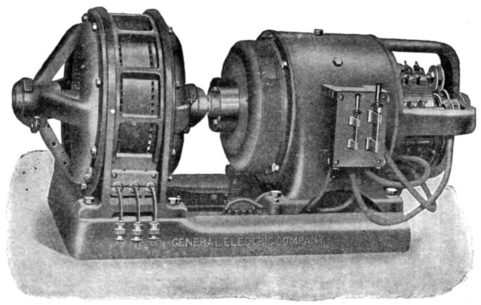
Fig. 2,067.—General Electric motor generator set consisting of 230 volt induction motor and 125 volt
dynamo.
In many
central stations
where
they supply a
great variety
of apparatus,
the motor
generator sets
are employed
as the generator
is independent
of
the alternating
current
line voltage
and any degree
of voltage
regulation
can be performed.
Motor
Generator
Combinations.—The
following
combinations
of motor generators are made and used to suit local conditions:
| Synchronous motor |
dynamo |
| Induction motor |
dynamo |
| Direct current motor |
dynamo |
| Direct current motor |
alternator |
| Synchronous motor |
alternator |
| Induction motor |
alternator |
[Pg 1486]

Fig. 2,068.—General Electric generator set, as installed for the Cleveland Electric Illuminating Company,
Cleveland, Ohio. It consists of 11,431 volt motor and 275 volt generator. Speed, 360 revolutions per minute.
Standard practice has adopted high tension alternating
current for transmission systems, but direct current distribution[Pg 1487]
is very frequently used. This is particularly true where alternating
current apparatus has been introduced in old direct
current lighting systems.
The synchronous motor or the induction motor connected to
a generator stands next in importance to the rotary converter
because it is easy to operate and the pressure may be changed
by a rheostat placed in the field circuit of the generator.
The line wires carrying full voltage can usually be connected
direct to the motor and thus do away with the necessary step-down
transformer required by the rotary.
Ques. What is the behavior of a rotary converter when
hunting?
Ans. It is liable to flash over at the direct current brushes,
which is common in high frequency converters where there are
a great number of poles and the brushes are necessarily spaced
close together around the commutator.
Ques. Is this fault so pronounced with motor generator
sets?
Ans. The motor generator operating on a high frequency
circuit, the generator can be designed with a few poles and the
brushes set far apart which will greatly reduce the chance of
flashing over.
A synchronous motor will drive a generator at a constant speed
during changes in load on it, and by having a field regulating resistance
it can be used to improve the power factor of the system.
When an induction motor is used its speed drops off slowly as the
load comes on the generator, and it is necessary to regulate the voltage
of the generator by means of a field rheostat, or compound wound
machines may be used.
While an induction motor requires no separate excitation of the
field magnets like the synchronous motor, its effect on the power factor
of the system is undesirable.
[Pg 1488]
Although it is seldom necessary to convert direct current to alternating,
such an arrangement of a direct current motor driving an
alternator is often justified in place of an inverted rotary converter,
as in this case the alternating current voltage can be changed independent
of the direct current voltage.
The racing of an inverted rotary under a heavy inductive load or
short circuit does not take place in motor generator set mentioned above.

Fig. 2,069.—General Electric frequency changer set, consisting of a 11,000 volt synchronous
motor with direct connected exciter and a 2,300 volt alternator.
Frequency Changing Sets.—A frequency of 25 cycles is
generally used on railway work and in large cities using the
Edison three wire system, and as a 25 cycle current is not desirable
for electric lighting it is necessary to change it to 60 cycles by
means of a frequency changer shown in fig. 2,069 for distribution
in the outlying districts.
[Pg 1489]
The two machines in this combination are of the same construction,
only the synchronous motor would have eight poles
and have the 25 cycle current passing through it, while the
generator would have 20 poles and produce 62½ cycles per
second at 300 revolutions per minute. By supplying the motor
with 24 cycles, the generator would produce 60 cycles.
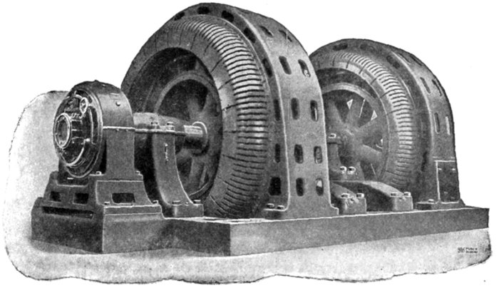
Fig. 2,070.—General Electric four unit frequency changer set consisting of a 11,000 volt
synchronous motor, 13,200 volt alternator, 250 volt exciter, and 440 volt starting induction
motor. Where parallel operation is required between synchronous motor driven frequency
changers, a mechanical adjustment is necessary between the fields or armatures of the
alternator and motor to obtain equal division of the load. The adjustment can be obtained
by shifting the keyway, or by special cradle construction. In the latter method,
one machine is bolted to a cradle fastened to the base. By taking out the bolts, the frame
can be turned around through a small angle relative to the cradle and therefore to the
armature frame of the other machine, when the bolts can be replaced.
It will be seen from the figure that the separate exciter is
fastened on the base plate and has its armature directly connected
to the shaft.
Parallel Operation of Frequency Changers.—It is very
difficult to construct two or more frequency changers and join
them to synchronous motors so that the current wave of one[Pg 1490]
machine will be in phase with the other, since the speed of the
motor will depend on the frequency of the line and be independent
of the load thrown on it.
When alternators are run in parallel, if one machine lag
behind, the other carries the load with the result that the lightly
loaded machine will speed up and get in step with the other, or
in other words a synchronizing current will flow between the
two alternators and tend to keep them in proper relation with
respect to phase and load.
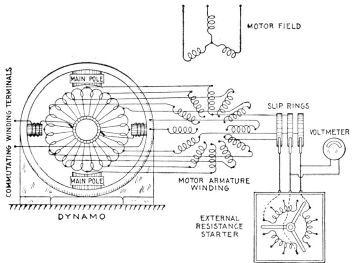
Fig. 2,071.—Diagram of "Cascade" motor generator set or motor converter, as it is called in
England where it is used extensively for electric railway work. In the diagram of motor
armature winding, some of the connections are omitted for simplicity. The windings are
Y connected, and as they are fed by wires joined to the slip rings at the right and center,
the rest of the power passes to the converter windings back to rotor winding and out to
the slip rings so that part of the power enters the rotor and part through the converter.
Cascade Converter.—This piece of apparatus was introduced
by Arnold and La Cour. Briefly, it consists of a combination
of an induction motor having a wound armature and[Pg 1491]
a dynamo, the armatures being placed on the same shaft. The
windings are joined in cascade, that is, in series with those of
the armature of the induction motor. The line supplies three
phase currents at high voltage direct to the field of the induction
motor and drives it, generating in it currents at a lower voltage
depending on the ratio of the windings.
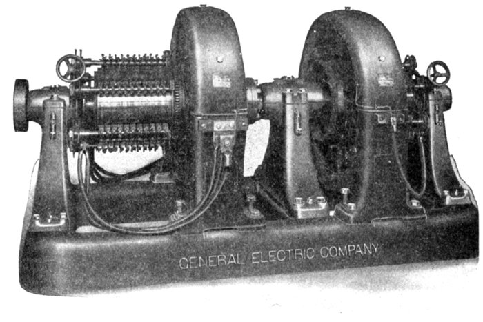
Fig. 2,072.—General Electric shunt wound booster set. Sets of this class are used in railway
stations to raise the pressure of the feeders extending to distant points of the system,
for storage battery charging and regulation, and in connection with the Edison three wire
lighting system. The design of the various sets is closely dependent upon their application.
Booster sets are constructed in either series or shunt wound types and they may be
arranged for either automatic or hand regulation, depending on the nature of the service
required. Where there are a number of lighting feeders connected and run at full load
for only a short time each day it will generally be economical to install boosters rather
than to invest in additional feeder copper. It is important, however, to consider each
case where the question of installing a booster arises, as a separate problem, and to determine
if the value of the power lost represents an amount lower than the interest charge
on the extra copper necessary to deliver the same voltage without the use of a booster.
Part of the current thus generated in the armature passes
into the armature of the dynamo and is converted by the[Pg 1492]
commutator into direct current as in a rotary converter, but is
also increased by the current induced in the winding of the
dynamo armature.
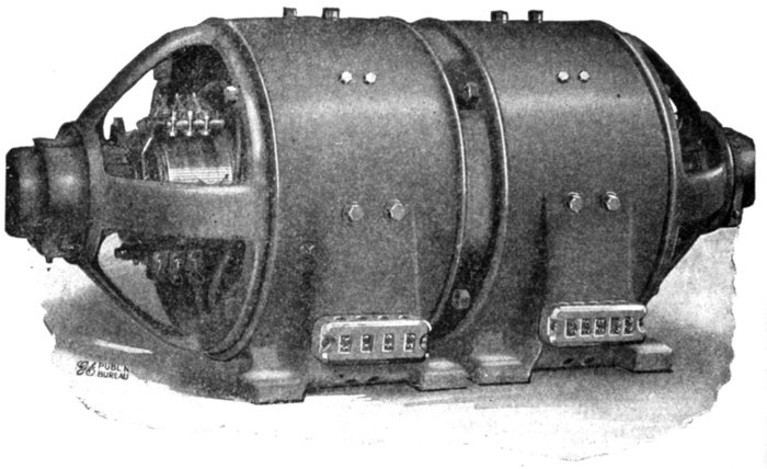
Fig. 2,073.—General Electric 9.5 kw. 1,000 R.P.M. balancer set. This is a form of direct
current compensator, the units of which it is composed may be alternately motor or
generator, and the secondary circuit is interconnected with the primary. Balancer sets
are widely used to provide the neutral of Edison three wire lighting systems. They are
also installed for power service in connection with the use of 250 volt motors on a 500 volt
service or 125 volt motors on a 250 volt service. Although the balancer set may be manufactured
for more than one intermediate voltage, the General Electric Company recommends
the three wire system as it is simpler. The motors may be more equally divided
and the reserve margin of the motor is more conservative for that class of work requiring
increase in torque with decrease in speed. The voltage of the system being given, the
capacity of a three wire balancer set is fixed by the maximum current the neutral wire is
required to carry. This figure is a more definite specification of capacity than a statement
in per cent. of unbalanced load. As designed for power work and generally for lighting
service, the brushes of each machine are set at the neutral point in order to get the best
results for operating alternately either as a generator or motor. Where the changes of
balance are so gradual as to permit of hand adjustment if desired, a considerable increase
in output is obtainable.
Ques. At what speed does the machine run?
Ans. Assuming equal numbers of pole, the armatures rotate
at a speed corresponding to one half the circuit frequency.
[Pg 1493]

Figs. 2,074 and 2,075.—General Electric charging sets. Fig. 2,074 set consists of dynamo and direct current motor; fig. 2,075
set consists of a dynamo and alternating current motor. Fig. 2,074 set is equipped with 125 volt, shunt wound dynamo
and 230 or 550 volt motor and range in capacity from .125 kw. to 13 kw., the speed varying from 2,250 R.P.M. in
the .125 kw. set to 925 R.P.M. in the 13 kw. set with 230 volt motor. Both motor and dynamo have the same type and size
of frame; these are bolted together and form a compact and symmetrical outfit, no base being necessary. Sets of the type
shown in fig. 2,075 range in capacity from .2 kw. to 10 kw. and are equipped with 125 volt shunt wound dynamo and 110,
220, 440 or 550 volt two or three phase motors. If desired they can be furnished with single phase motors wound for 110 or
220 volts. The speed of this type is 1,800 R.P.M. When a motor generator set is used to charge only one battery, the
insertion of a resistance between the charging dynamo and the battery is not necessary, inasmuch as all adjustments of
voltage can be made by varying the field strength of the dynamo, and, therefore, there are no large losses due to resistance
since the loss in the dynamo field rheostat is very small. When a motor generator set is used to charge two or more batteries
of different capacities, or voltages, or which are in different conditions of charge, it is necessary to insert a resistance
in series with each battery, in order that the current may be properly adjusted for each particular battery.
Thus if the motor
have six poles and
the frequency be 50,
the rotary field revolves
at 50 × 60
÷ 3 = 1,000 R.P.M.
and the motor will
revolve at one-half
that speed or 1,000
÷ 2 = 500 R.P.M.
Since the connections
are so arranged
that these
currents tend to
set up in the armature
a revolving
field, rotating at
half speed in a sense
opposite to that in
which the shaft is
rotating at half
speed, it follows
that by the super-position
of this revolving
field upon
the revolutions of
the machine, the
magnetic effect is
equivalent to a rotation
of the armature
at whole speed,
so that it operates
in synchronism, as
does the armature
of a rotary converter.
Half the electric
input into the motor
part is, therefore,
turned into
mechanical energy
to drive the shaft,
the other half
acts inductively on
the armature winding,
generating currents
therein.
[Pg 1494]
As to the dynamo part it is half generator, receiving mechanical
power by transmission along the shaft to furnish half its output, and it
is half converter, turning the currents received from the armature into
direct current delivered at the brushes.
Ques. What action takes place in the motor armature
winding?
Ans. Since it runs at one-half synchronous speed, it generates
alternating current of half the supply current frequency, delivering
these to the armature of the dynamo.
Ques. What claim is made for this type of apparatus?
Ans. The cost is said to be less than a motor generator set,
and it is claimed to be self-synchronizing and to require no
special starting gear, also to be 2.5 per cent. more efficient than
a motor generator.
Ques. How is the machine started from the high
pressure side?
Ans. The field winding is connected directly to the high
pressure leads. The three slip ring brushes are connected with
external resistances which are used while starting, the external
resistances being gradually cut out of the circuit as the machine
comes up to speed (the same as with an ordinary slip ring motor).
Ques. How does a cascade converter compare with a
synchronous converter?
Ans. It is about equally expensive as the synchronous
converter with its necessary bank of transformers, but is about
one per cent. less efficient. It is claimed to be more desirable
for frequencies above 40 on account of the improved commutation
at the low frequency used in the dynamo member. For
lower frequencies the synchronous converter is preferable.
[Pg 1495]
CHAPTER LIV
RECTIFIERS
The purpose of a rectifier is to change alternating current
into a uni-directional or pulsating current. There are several
classes of apparatus to which the term rectifier may be
applied, as
- 1. Mechanical rectifiers;
- 2. Electrolytic rectifiers;
- 3. Mercury vapor rectifiers, or, mercury arc rectifiers;
- 4. Electro-magnetic rectifiers.
Mechanical Rectifiers.—By definition, a mechanical rectifier
is a form of commutator operating in synchronism with the
generator and commutating or rectifying the negative waves
of the alternating current as shown graphically in figs. 2,076 and
2,078. The essential features of construction are shown in fig.
2,079.
Ques. Mention some application of a mechanical
rectifier.
Ans. It is used on a compositely excited alternator as illustrated
on page 1,192.
Electrolytic Rectifiers.—If two metals be placed in an electrolyte
and then subjected to a definite difference of pressure,
they will (under certain conditions) offer greater resistance to the[Pg 1496]
passage of a current in one direction, than in the other direction.
On account of this so called valve effect, electrolytic rectifiers
are sometimes called "valves."
Ques. What metal is generally used for the cathode?
Ans. Aluminum.
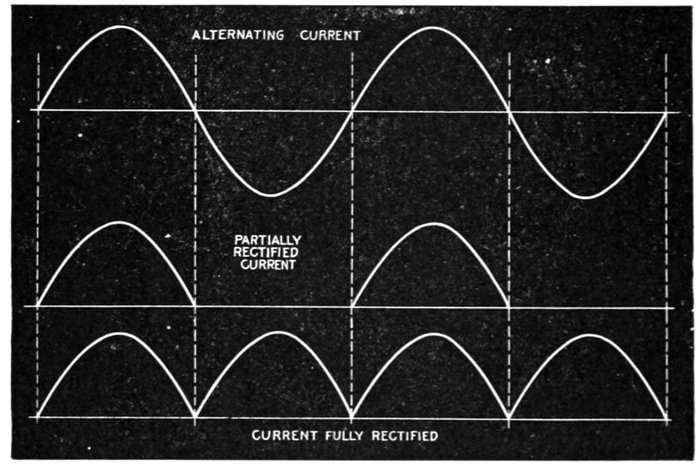
Figs. 2,076 to 2,078.—Diagrams showing alternating currents, and partial and complete rectification.
Ques. What is generally used for the other electrode?
Ans. Lead or polished steel.
Metals of low atomic weight exhibit the valve effect at high differences
of pressure, and heavier metals at low differences of pressure.
Ques. Describe the "Nodon valve."
Ans. The cathode is of aluminum or aluminum alloy, and the[Pg 1497]
other electrode, which has considerably more surface, is the
containing vessel. The electrolyte is a neutral solution of
ammonia phosphate.
Ques. Describe its action.
Ans. It is due to the formation of a film of normal hydroxide
of aluminum, over the surface of the aluminum electrode. This
film presents a very high resistance to the current when flowing
in one direction but very little resistance, when flowing in the
reverse direction.
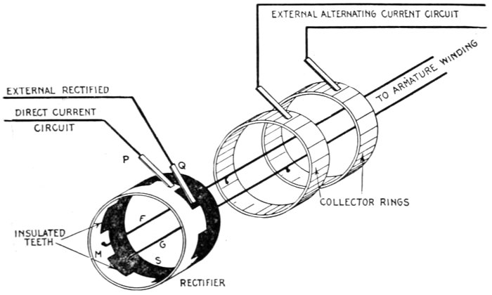
Fig. 2,079.—Mechanical rectifier. The rectifier consists of two castings M and S with teeth
which fit together as shown, being insulated so they do not come in contact with each
other. Every alternate tooth, being of the same casting, is connected together, the
same as though joined by a conducting wire. There are as many teeth as there are poles.
The part M of the rectifier is connected to one of the collector rings by F, and the part
S to the other ring by G.
Ques. What is the effect when a Nodon cell is supplied
with alternating current?
Ans. Half of the wave will be suppressed and an intermittently
pulsating current will result as shown in fig. 2,077.
[Pg 1498]
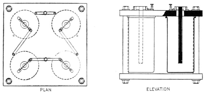
Figs. 2,080 and 2,081.—Two views of Nodon valve. This is an electrolytic rectifier in which
the cathode is a rod of aluminum alloy held centrally in a leaden vessel which forms the
anode and contains the electrolyte, a concentrated solution of ammonium phosphate.
Only a short portion at the lower end of the cathode is utilized, the rest, which is rather
smaller in diameter, being protected from action by an enclosing glass sleeve. The current
density at the cathode ranges from 5 to 10 amp. per sq. dm. In the larger sizes, the cells
are made double, and a current of air is kept circulating between the walls by means of
a motor driven fan. In order to utilize both halves of the supply wave, the Gratz method
of connection is adopted. The maximum efficiency is obtained at about 140 volts, and
the efficiency lies between 65 and 75 per cent., and is practically independent of the frequency
between the limits of 25 ~ and 200 ~. Above a pressure of 140 volts, the efficiency
falls off very rapidly, owing to breakdown of the film. The pressure difference is
high, being over 90 per cent. at full load. Temperature largely influences the action of
the valve, and should never exceed 122° Fahr.
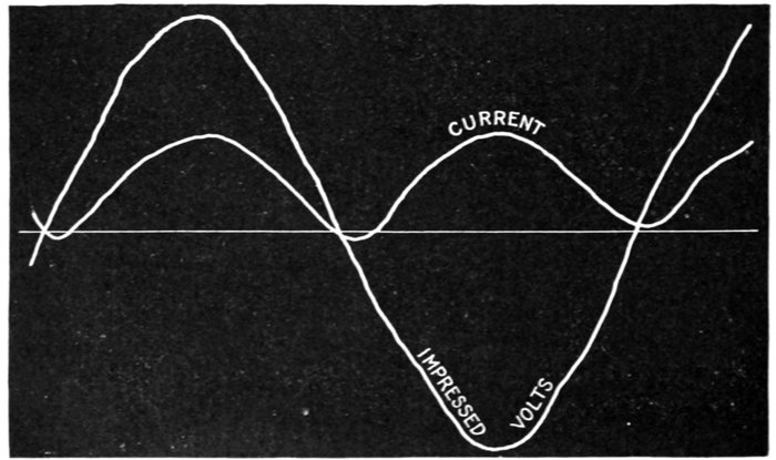
Fig. 2,082.—Oscillograph record from Nodon valve showing original supply voltage and the
corresponding pulsating current at the terminals of such a valve.
[Pg 1499]
Ques. How may both halves of the alternating waves
be utilized?
Ans. By coupling a series of cells in opposed pairs as in fig.
2,080.
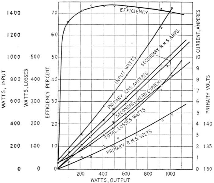
Fig. 2,083.—Performance curves of five ampere Nodon valve. Constant secondary voltage
test. Loaded on non-inductive resistances. Frequency 50. Maximum power factor
on valve .7.
Ques. Upon what does the efficiency of the film depend?
Ans. Upon the temperature.
It should not for maximum efficiency exceed 86 degrees Fahr. There
is also a certain critical voltage above which the film breaks down
locally, giving rise to a luminous and somewhat disruptive discharge
accompanied by a rapid rise of temperature and fall in efficiency.
[Pg 1500]
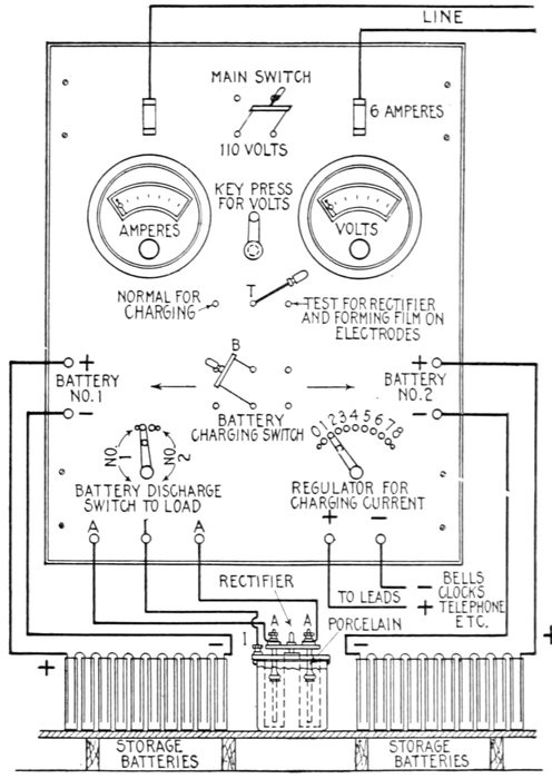
Fig. 2,084.—Mohawk electrolytic rectifier and switchboard; diagram showing connections
for charging storage battery. Operating instructions: After assembling battery as in
fig. 2,085, the film must be formed on the aluminum alloy electrodes so that the rectifier
will pass current only in the right direction. Open switch B, close switch T to the right;
discharge lever can be in any position; charging regulator lever must be to the extreme
left, the zero position; now close main switch M. Moving regulator lever R from the zero
position to the first button or contact, let it remain there for a time, not less than five minutes;
this is important, as the proper rectification of the current depends on the film formed
on the aluminum rods. The ammeter after the first rush of current may not show any
current as passing, or it may show a reverse current. In the latter case, leave the contact
finger on the first button until the needle comes back to zero. This may take some time,
but the needle will eventually come back; it also indicates that the film is properly formed
when the needle returns to zero. Move regulator R to the extreme right step by step and
note that the ammeter continues to return to zero, which indicates that the film on rectifier
electrodes is formed properly. Move regulator R to zero, close switch T to the left in normal
charging position. Close charging switch B. To regulate the flow of current through the
battery move charging lever R to the right slowly until ammeter indicates the correct charging
current. After the batteries are charged and ready for use, discharge lever can be moved
to connect either set of storage batteries to the load terminal. The voltage of the batteries
can be read at any time, by pressing the strap key. The discharge lever connects the batteries
to the volt meter and it is possible by moving it to measure the voltage of either set
of battery, charging or discharging. Trouble in the rectifier demonstrates itself by the
solution becoming heated. The condition of the rectifier can be tested any time in a few
seconds by opening switch B and closing switch T to the right. If the rectifier be in
proper condition the ammeter will read zero. And if it be not rectifying and permitting A. C.
current to flow through the rectifier, the ammeter will read negative or to the left of the zero.
An old solution that is heating and not rectifying properly will turn a reddish brown color.
[Pg 1501]
Ques. When an electrolytic rectifier is not in use for
some time what happens?
Ans. The electrodes will loose the film.
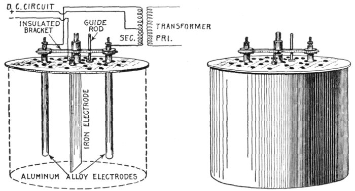
Figs. 2,085 and 2,086.—Mohawk electrolytic rectifier. To put in commission, clean out the jar.
Fill with distilled or rain water. Add six pounds of electro salts, stir and after all salts are
dissolved place the cover in position. The specific gravity of the solution should be 1.125.
The middle iron electrode must hang straight down in the solution and not touch either
of the other aluminum alloy electrodes. The aluminum alloy electrodes are mounted on an
insulated bracket that slides up and down on a ¼" rod. This rod screws in the hole
taped in the middle of the cover. The electrodes give the best results only when perfectly
smooth. Should they get rough, covered with a deposit or a white coating remove from
the solution, and clean with fine sand paper. Finish with fine sand paper. Form the
film again and the electrodes will be as good as new. Clean iron electrode occasionally.
[Pg 1502]
Ques. What must be done in such case?
Ans. The electrodes must be reformed.
Ques. How is the loss of film prevented?
Ans. By Removing the electrodes from the electrolyte and
drying them.
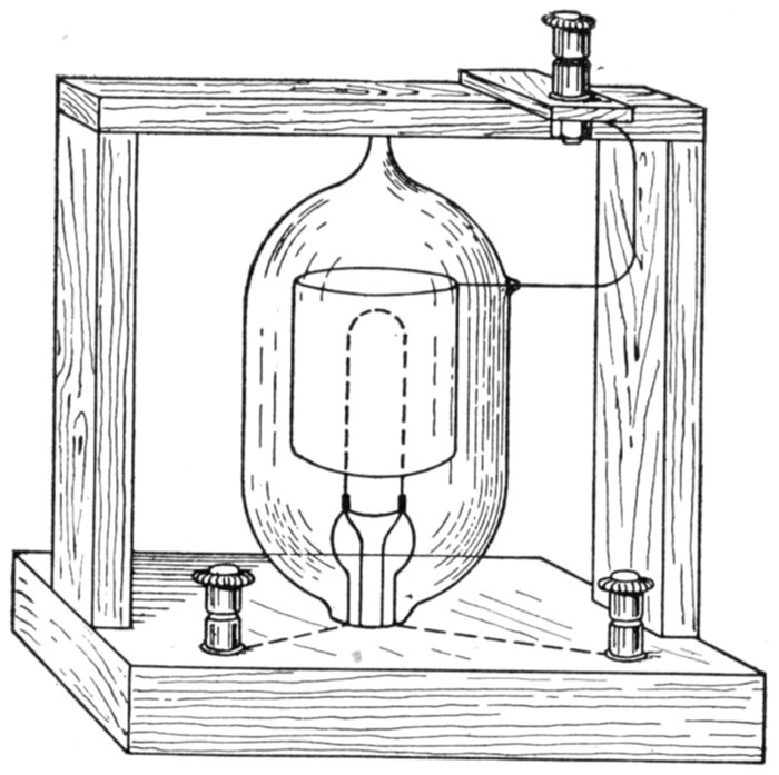
Fig. 2,087.—The Fleming oscillation valve. It depends for its action on the well-known
Edison effect in glow lamps. The valve consists of a carbon filament glow lamp with a
simple central horseshoe filament. Around this filament inside the exhausted bulb is
fixed a small cylinder of nickel, which is connected by means of a platinum wire sealed
through the bulb to a third terminal. The valve is used as follows: The carbon loop is
made incandescent by a suitable battery. The circuits in which the oscillations are to
be detected is joined in series with a sensitive mirror galvanometer, the nickel cylinder
terminal and the negative terminal of the filament of the valve being used. The galvanometer
will then be traversed by a series of rapid discharges all in the same direction, those
in the opposite direction being entirely suppressed.
Ques. What attention must be given to the electrolyte?
Ans. Water must be added from time to time to make up
for evaporation.
This is necessary to keep the solution at the proper density.
[Pg 1503]
Ques. What is the indication that the rectifier needs
recharging?
Ans. Excessive heating of the solution with normal load.
Ques. What is the indication that a rectifier is passing
alternating current?
Ans. It will heat, and if the solution be very weak, it will
cause a buzzing sound.
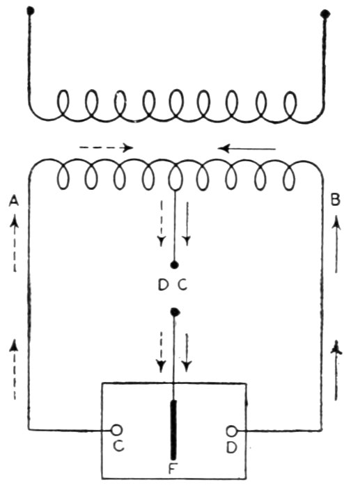
Fig. 2,088.—The Churcher valve. This is of the modified Nodon type. It differs from the latter
in that it has two cathodes of aluminum and an anode of lead or platinum, suspended in
the one cell. This permits the complete utilization of both halves of the supply wave
with one cell instead of the four required in the Gratz method. The connections of
such a cell are shown in the figure. The secondary of the transformer carries a central
tapping, and is connected through the direct current load to the central anode, while each
of the cathodes is connected to the ordinary terminals of the transformer itself. The
practical limits of the cell are 50 volts direct current, or 130 volts at the transformer terminals
AB. F, is the anode; C, cathode I; D, cathode II.
Ques. What harm is caused by operating a rectifier
with a weak electrolyte?
Ans. The electrodes will eat away.
[Pg 1504]
A few of the so called electrolytic valves are here briefly described:
The Audion Valve.—This valve was invented by De Forest in 1900
and is practically identical with the Fleming oscillation valve, the
latter being illustrated in fig. 2,086.
Grisson Valve.—In this valve the cathode is a sheet of aluminum,
and the anode, a sheet of lead, supported, in the original form, horizontally
in a vessel containing the electrolyte, consisting of a solution
of sodium carbonate. Cooling is effected by circulating water through
metal tubes in the electrolyte itself.

Figs. 2,089 and 2,090.—The De Faria valve. This is an aluminum lead rectifier. The cathode
is a hollow cylinder of aluminum placed concentrically in a larger cylinder of lead, and
the whole immersed in electrolyte of sodium phosphate in an ebonite containing vessel.
Cooling is effected by promoting automatic circulation of the electrolyte by providing the
lead cylinder with holes near its extremities; the heated electrolyte then rises in the lead
cylinder, passes out at the upper holes, is cooled by contact with the walls of the containing
vessel, and descends outside the lead cylinder. It is claimed that this cooling
action is sufficient to allow of a current density of 8 amp. per sq. dm. of aluminum.
Pawlowski Valve.—This is an electrolytic valve employing a solid
electrolyte. It consists of a copper plate which has been coated with a
crystalline layer of carefully prepared copper hemisulphide, prepared by
melting sulphur and copper together out of contact with air. The prepared
plate is placed in contact with an aluminum sheet and the combination
is then formed by submitting it to an alternating pressure
until sparking, which at first occurs, ceases.
[Pg 1505]
Giles Electric Valve.—This consists of a combination of spark gaps
and capacity used to protect electrical apparatus against damage due to
atmospheric discharges and resonance surges. The spark gaps are
formed between the edges of sharp rimmed discs of non-arcing metal.
These discs are insulated from each other, and from the central tube,
which provides a support for the apparatus and also an earth. The
condenser effect is obtained by means of the annular discs and the tube;
an adjustable spark gap, a high resistance, and a fuse all connected in
series, complete the valve.
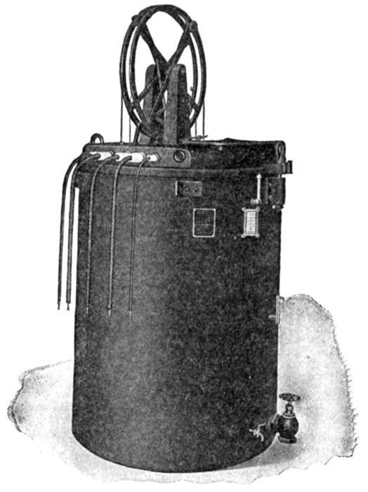
Fig. 2,091.—75 light Westinghouse-Cooper Hewitt mercury vapor rectifier constant current
regulating transformer. View showing assembly in case.
Buttner Valve.—It is of the Nodon type employing a cathode of
magnesium-aluminum alloy, and probably iron or lead as anode, with
an electrolyte of ammonium borate. Buttner claims that the borate is
superior to the phosphate in that it does not attack iron, and will keep
in good working condition for longer periods.
[Pg 1506]

Fig. 2,092.—75 light Westinghouse-Cooper Hewitt mercury vapor rectifier constant current
regulating transformer with case removed. The transformer is of the repulsion coil type,
oil cooled and oil insulated. It is so arranged as to give a constant secondary current
and to insulate the arc lines from the primary circuit. The regulating transformer contains
two stationary secondary coils and two moving primary coils balanced against
each other. Each secondary coil of the 75 light regulator is wound in two parts, owing
to the use of two rectifier bulbs in series in outfits of this capacity. The repulsion between
the primary and secondary coils changes the distance between them according to the
variation of load, and the induced current in the secondary is thus kept constant. An
increase in current causes the primary and secondary coils to separate, and a decrease in
current permits them to approach each other, until the normal balance is restored. The
moving coils are hung from sheave wheels having roller bearings and are balanced so that
they are sensitive to the slightest impulse tending to separate them or draw them closer
together. (See figs. 1,981-2, and 2,111.) The windings are insulated for a voltage considerably
in excess of that existing in normal service. Several taps are provided to take
care of different voltages and wave forms. A combination of taps will be found which
will be suitable for any wave form coming within the American Institute of Electrical
Engineer's limits for a sine wave. The secondary coils are also provided with taps for
85 per cent. of normal load, so that less than normal load can be taken care of at a good
power factor. Any part of the full load can be carried temporarily with the full load
connections of the transformer, but at permanent light loads the power factor and efficiency
will be improved by using the 85 per cent. connections. Standard regulating
transformers are wound for 6.6 and 4 amperes, and for primary circuits of 220, 440, 1,100
2,200, 6,600 and 13,200 volts. Regulators can be specially wound for 5.5 amperes. For
three phase circuits three regulators can be used, one on each phase, or they can be furnished
in pairs with an auxiliary auto-transformer to give a balanced load. The regulators
can be connected, in cases where the unbalancing is not objectionable, to separate phases.
[Pg 1507]
Mercury Vapor Rectifiers.—The Cooper Hewitt mercury
vapor rectifier, as shown in fig. 2,093 consists essentially of a
hermetically sealed glass bulb filled with mercury vapor and provided
with four electrodes. The two upper electrodes are of solid
material and the two lower of mercury.
The solid electrodes are the positive electrodes; the mercury
electrodes are the negative electrodes.
The mercury pools of the two lower electrodes are not in
contact when the bulb is vertical, but the bulb is so mounted
that it can be tilted to bring these two pools temporarily in
contact for starting.
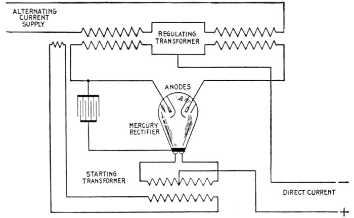
Fig. 2,093.—Diagram of connections of Westinghouse-Cooper Hewitt mercury vapor rectifier
arc light circuit.
The bulb contains highly attenuated vapor of mercury, which,
like other metal vapors, is an electrical conductor under some
conditions. The positive electrodes are surrounded by this[Pg 1508]
vapor. Current can readily pass from either of the solid
electrodes to the mercury vapor and from it to the mercury
electrode, but when the direction of flow tends to reverse, so
that current would pass from the vapor to the solid electrode,
there is a resistance at the surface of the electrode, which entirely
prevents the flow of current.
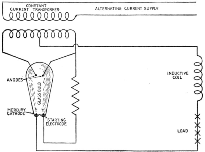
Fig. 2,094.—Cooper Hewitt mercury vapor rectifier. The mercury vapor rectifier as developed
by Peter Cooper Hewitt for changing alternating current into direct current is the result
of a series of careful experiments and investigations of the action going on in his mercury
vapor lamp for electric lighting used on direct current circuits only. While many attempts
have been made to produce an alternating current lamp, up to the present time, they have
been unsuccessful. The difficulty of operating a lamp on the alternating current circuit
lies in the fact that while a current will flow freely through it in one direction, when the
current reverses the negative electrode or cathode acts as an electric valve and stops the
current, thus breaking the circuit and putting out the light. By following up this new
electrical action, Hewitt applied the principle in the construction of a vacuum tube with
suitable electrodes, and by using two electrodes of iron or graphite for the positive or incoming
current and one of mercury for the negative or where the current leaves the tube,
the circuits could be arranged so that a direct current would flow from the mercury electrode
and be used for charging storage batteries, electro-chemical work or operating direct current
flame arc lamps. As shown in the figure, the rectifier consists essentially of a glass bulb
into which are sealed two iron or graphite anodes and one mercury cathode, and a small starting
electrode. The bulb is filled with mercury vapor under low pressure. The action of this
device depends on the property of ionized mercury vapor of conducting electricity in one direction
only. In operation no current will flow until the starting or negative electrode resistance
has been overcome by the ionization of the vapor in its neighborhood. To accomplish
this, the voltage is raised sufficiently to cause the current to jump the gap between the mercury
cathode and the starting cathode, or by bringing the cathode and starting electrode
together in the vapor by tilting and then separating them, thus drawing out the arc. When
this has been done, current will only flow from the anode to the mercury cathode, and not
in the reverse direction. In order to maintain the action, a lag is produced in each half
wave by the use of a reactive or sustaining coil; hence the current never reaches its zero
value, otherwise the arc would have to be restarted. There are two kinds of losses in the
tube: 1, arcing, or leakage from one anode to the other, and 2, the mercury arc voltage drop.
This drop does not depend on the load, the energy represented by the drop being converted
into heat, which is dissipated at the surface of the containing vessel. According to Steinmetz,
the limit of voltage must be very high, as 36,000 volts has been rectified. The current
output is limited principally by the leading-in wires to the electrodes, it being a difficult
problem to seal into the glass container the large masses of metal required for the conduction
of large currents. Frequency has but little influence. The direct current voltage ranges
from 20 to 50 per cent. that of the arc supply. The life of the valve depends somewhat
upon its size, being longer in the small sizes and never, with fair usage, less than 1,000 hours.
[Pg 1509]
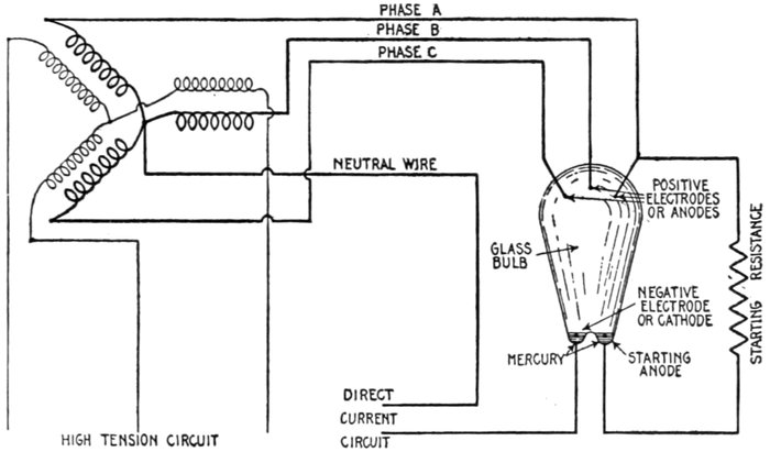
Fig. 2,095.—Three phase mercury arc rectifier. The rectifier bulb is provided with three
positive electrodes or anodes, a negative electrode or cathode, and a starting anode, as
shown. The three phase leads are connected to the anodes at the top of the bulb, a
branch from one phase being brought down to the starting anode, a resistance being placed
in the circuit to prevent excessive current on account of the proximity of the two lower
electrodes. Since there is always a pressure on one of the three anodes in the right direction,
a reactance coil is not necessary. The apparatus is started in the usual way by tilting.
The alternating current supply circuit is connected to the two
positive electrodes as shown in the diagram, and as the electrodes
will allow current to flow in only one direction and oppose any
current flow in the opposite direction, the pulsations of the
current pass alternately from one or the other of the positive
electrodes into the mercury.
[Pg 1510]
As these currents cannot pass from the vapor into either
positive electrode, they are constrained to pass out all in one
direction through the mercury electrode, from which they
emerge as a uni-directional current. The positive electrodes
of the rectifier thus act as check valves, permitting current to
pass into the mercury vapor but not allowing it to pass from
the vapor to the solid electrodes.
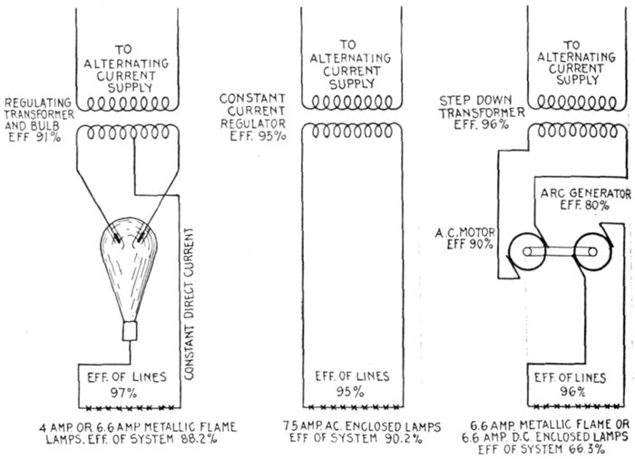
Figs. 2,096 to 2,098.—Westinghouse diagrams showing comparative efficiencies of different
systems of series arc lighting.
Ques. What condition prevails before the bulb starts
to rectify?
Ans. There appears to be a high resistance at the surface
[Pg 1511]
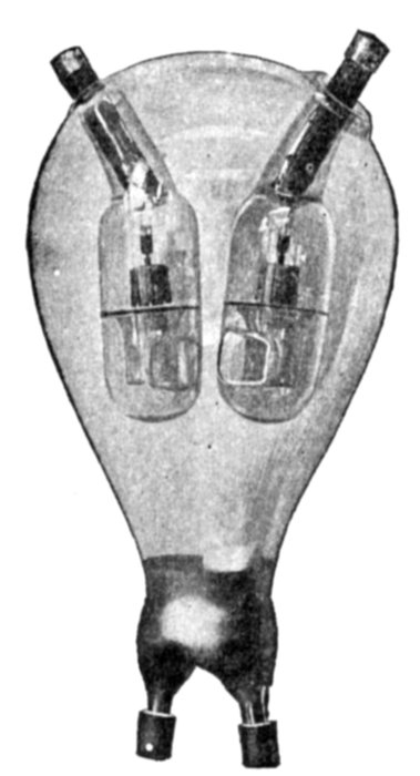
Fig. 2,099.—Westinghouse-Cooper
Hewitt mercury vapor rectifier bulb.
It consists essentially of a hermetically
sealed glass bulb filled with
highly attenuated vapor of mercury,
and provided with electrodes. Its
operation is fully explained in the
accompanying text.
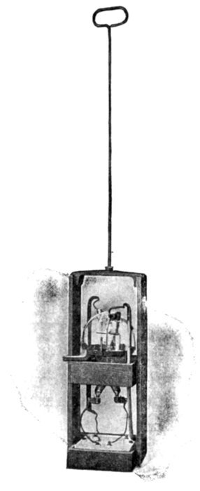
Fig. 2,100.—Westinghouse-Cooper Hewitt
mercury vapor rectifier bulb and box.
The life of the bulb is materially increased
by operating it at certain temperatures
and for this reason the bulbs
in the arc light rectifier outfits are immersed
in oil and mounted in the same
tank with the regulating transformer.
Two bulbs in series are used with the
75 light outfit. The bulb is mounted on
tilting trunnions in a box which can be
lifted out through a door in the top of the
tank without disconnecting any leads.
The containing box has contacts on the
bottom so arranged that when it is lowered
into place, the bulb is automatically
connected in circuit. To replace a defective
bulb it is only necessary to lift
out the containing box by its handle
through the door in the top of the case
and mount a new bulb in it, after which
the box can be lowered into place. It is
desirable to have at each installation, a
spare bulb box in which a bulb can be
kept, connected ready for use. If this be
done, it is only necessary, in case of
trouble with the bulb, to withdraw the
old bulb and box and replace them with
the spare set. This avoids having the
lamps out of service.
[Pg 1512]
of the mercury, which must be broken down so that the current
can pass.
Ques. What is this apparent surface resistance called?
Ans. The negative electrode resistance.
Ques. What must be done before any current can pass?
Ans. The negative electrode resistance must be overcome.
When once started the current will continue to flow, meeting with
practically no resistance as long as the current is uninterrupted.
Ques. What will happen if the current be interrupted
even for the smallest instant of time?
Ans. The negative electrode resistance will re-establish
itself, and stop the operation of the bulb.
Ques. How is the negative electrode resistance overcome?
Ans. The bulb is tilted or shaken so that the space between
the mercury electrodes is bridged by the mercury.
Ques. What happens when the bulb is tilted?
Ans. Current then passes between the two mercury electrodes
from the starting transformer and the little stream of
mercury which bridges the space between the electrodes breaks
with a spark as the bulb is returned to its vertical position.
Ques. What duty is performed by the spark?
Ans. It breaks down the negative electrode resistance.
Ques. What conditions are now necessary for continuous
operation of the rectifier?
Ans. The rectifier will now operate indefinitely as long as
the current supply is uninterrupted and the direct current load
does not fall below the minimum required for the arc.
[Pg 1513]
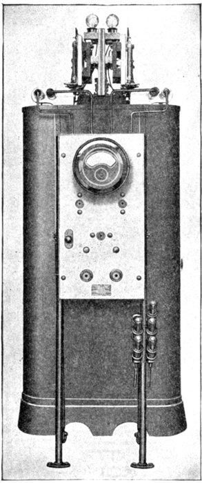
Fig. 2,101.—General Electric 50 light double tube combined unit series mercury arc rectifier
outfit; front view. This unit consists of a constant current transformer, reactance, tube
tank and exciting transformer mounted on a common base; also a static discharger and
pilot lamp mounted on top of the transformer. This arrangement makes the rectifier
outfit, with the exception of the switchboard panel, complete in itself.
Ques. Is the rectifier
self-starting?
Ans. After the bulb has
been started a few times, as
described above, it becomes
self-starting, so that under
all ordinary operating conditions
it will commence
to operate when the
switches connecting it with
the load and the alternating
current supply are
closed.
Ques. What provision
is made in the Westinghouse-Cooper
Hewitt
rectifier to render it
self-starting?
Ans. It is rendered self-starting
by means of a
condenser.
Ques. Describe the
arrangement and operation
of the condenser.
Ans. The condenser is
connected between one of
the positive electrodes and
a coating of tinfoil outside[Pg 1514]
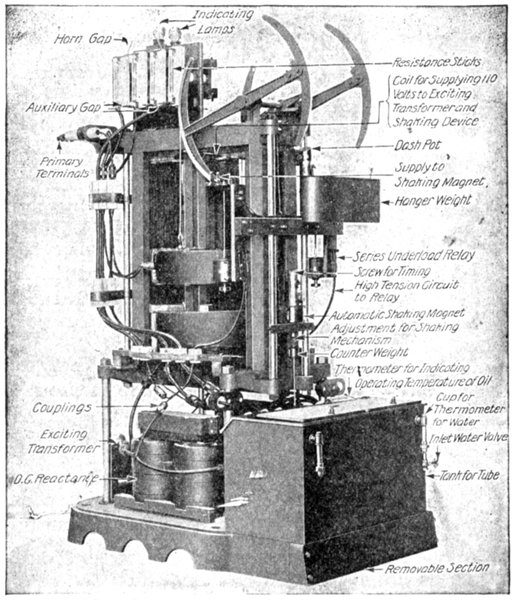
Fig. 2,102.—General Electric 2,200 volts, 60 cycle, primary, 6.6 ampere, secondary, 75 light,
double tube mercury arc rectifier outfit with automatic shaking device, the case being
removed to show parts. The constant current transformer is air cooled. The winding
which supplies energy for the exciter transformer is located at the top of, and around
the core of the constant current transformer. The exciting transformer is mounted on
the base of the constant current transformer inside of the casing. It supplies low pressure
currents to the starting anodes of the rectifier tube. This current establishes an auxiliary
arc when the tube is shaken, which is necessary in order to start the rectifier. The exciting
transformer is wound for 110 volts and it consumes about 200 volt-amperes. The
direct current reactance is mounted on the base of the transformer and enclosed in the
same casing. It is connected in series with the lamp load and its function is to reduce the
pulsations of the circuit to a value most satisfactory for operation. The tube tank for holding
the oil is mounted on the same base as the transformer. It is provided with a cooling
coil; a tube carrier is provided for raising or lowering the tube in the tank. A thermometer
is provided to gauge the temperature of the oil in the tank. The static dischargers consisting
of horn gaps in series with resistance, are connected between the anodes and the cathode
in order to protect the tubes and other apparatus from excessive electrical strains. The
horn gaps open the circuit after discharge, and in case the resistance becomes damaged the
discharge passes across the spark gap provided, thereby shunting the resistance.
[Pg 1515]
the part of the bulb containing the mercury, and induces static
sparks on the surface of the mercury which break down the
negative electrode resistance.
The action of the rectifier will be better understood by reference to
the diagram of current waves and impressed pressure as shown in
figs. 2,103 to 2,106.
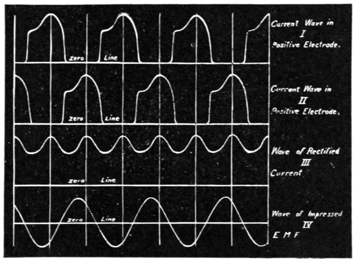
Figs. 2,103 to 2,106.—Diagram of current waves and impressed pressure of Westinghouse-Cooper
Hewitt mercury vapor rectifier. The whole of the alternating current wave on both sides
of the zero line is used. The two upper curves in the diagram show the current waves
in each of the two positive electrodes, and the resultant curve III represents the rectified
current flowing from the negative electrode. Curve IV shows the impressed alternating
current pressure. It is evident that if the part of the wave below the zero line were reversed,
the resulting current would be a pulsating direct current with each pulsation
varying from zero to a positive maximum. Such a current could not be maintained by
the rectifier, because as soon as the zero value was reached the negative electrode resistance
of the rectifier would be re-established and the circuit would be broken. To avoid
this condition, reactance is introduced into the circuit, which causes an elongation of
current waves so that they overlap before reaching the zero value. The overlapping of
the rectifier current waves reduces the amplitude of the pulsations and produces a comparatively
smooth direct current as shown in curve III. In this way the whole of the alternating
current is transformed to direct current because each of the alternations in both
directions is alternately rectified.
Ques. Describe a mercury vapor rectifier outfit for
series arc lighting.
Ans. It consists of a constant current regulating transformer,[Pg 1516]
a rectifier bulb, and a control panel containing the necessary
switches, meters, etc. The transformer and rectifier bulb are
mounted in the same tank.
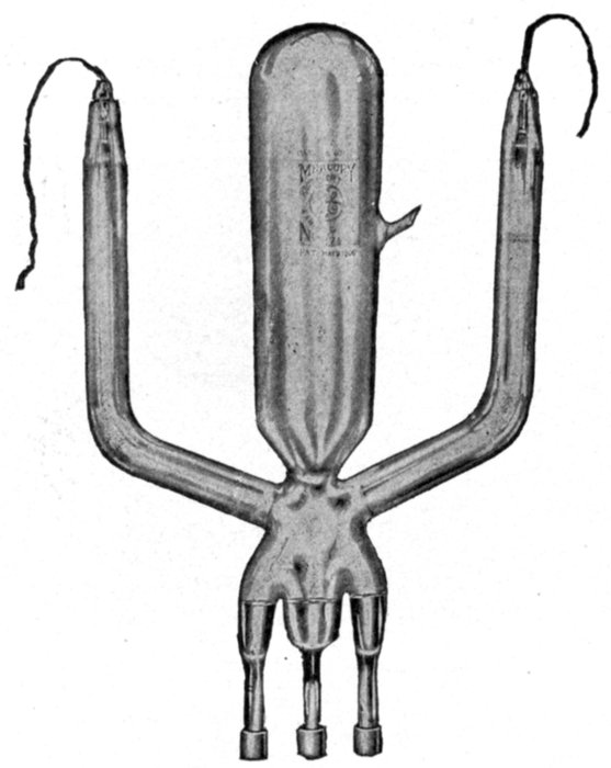
Fig. 2,107.—General Electrical rectifier tube as used on series mercury arc rectifier. The
tube rectifies the alternating current into direct current. It consists of an exhausted
glass vessel containing one anode or positive terminal in each of the two upper arms, two
mercury starting anodes and a cathode or negative terminal of mercury at the bottom
of the tube. It is submerged in oil and supported in a removable carrier. The tube is
put into operation by slightly shaking it. In the combined unit set, this shaking is accomplished
by an electromagnet mounted above the tube tank and operated from a pull
button switch on the panel. An automatic shaker is sometimes installed which will
automatically start the tube when the set is started, or if its operation should become
interrupted while in service. The energy for the operation of this magnet (110 volts
alternating current) is obtained from the small auxiliary winding on the main transformer
which also supplies energy to the exciting transformer. The oil in which the tube is placed
is cooled by a circulation of water through the cooling coils on the inside of the tube tank.
The amount of water necessary for cooling the rectifier tubes varies according to local
conditions, depending upon the temperature of the water and that of the air in the station
but under the most favorable conditions no water is required. As rectifiers are commonly
installed in steam driven stations, the drip from the tube tanks is usually piped to the
boiler supply thereby eliminating any loss for cooling water.
[Pg 1517]
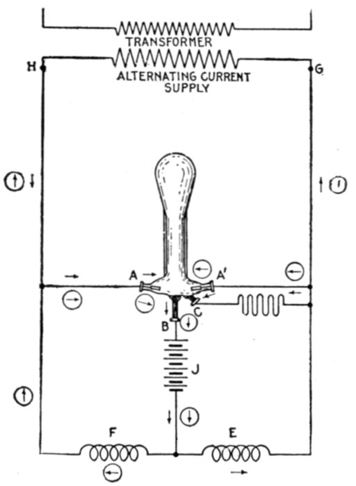
Fig. 2,108.—Elementary diagram of mercury arc rectifier connections. A.A., graphite anodes;
B, mercury cathode; C, small starting electrode; D, battery connection; E and F, reactance
coils; G and H, transformer terminals; J, battery.
Ques. Describe the construction and operation of the
mercury arc[11] rectifier shown in fig. 2,108.
Ans. Fig. 2,108 is an elementary diagram of connections.
The rectifier tube is an exhausted glass vessel in which are two
graphite anodes A, A', and one mercury cathode B. The small
starting electrode C is connected to one side of the alternating
circuit, through resistance; and by rocking the tube a slight arc
is formed, which starts the operation of the rectifier tube. At
the instant the terminal H of the supply transformer is positive,
the anode A is then positive, and the arc is free to flow between
A and B. Following the direction of the arrow still further, the
[Pg 1518]current passes through the battery J, through one-half of the
main reactance coil E, and back to the negative terminal G of
the transformer. When the impressed voltage falls below a
value sufficient to maintain the arc against the reverse pressure
of the arc and load, the reactance E, which heretofore has been
charging, now discharges, the discharge current being in the same
direction as formerly. This serves to maintain the arc in the
rectifier tube until the pressure of the supply has passed through
zero, reversed, and built up such a value as to cause the anode
A to have a sufficiently positive value to start the arc between
it and the cathode B. The discharge circuit of the reactance
coil E is now through the arc A'B instead of through its former
circuit. Consequently the arc A'B is now supplied with current,
partly from the transformer, and partly from the reactance coil E.
The new circuit from the transformer is indicated by the arrows
enclosed in circles.
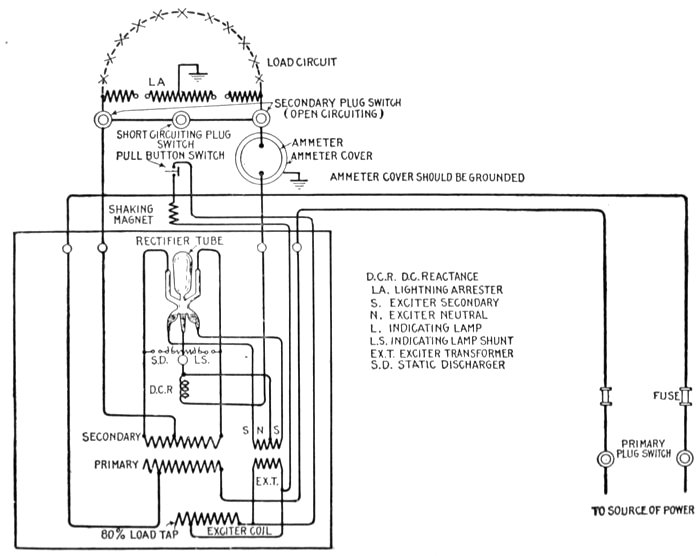
Fig. 2,109.—Diagram showing connections
of General Electric combined
unit mercury arc single
tube rectifier outfit with remote
controlled non-automatic shaking
device.
[Pg 1519]
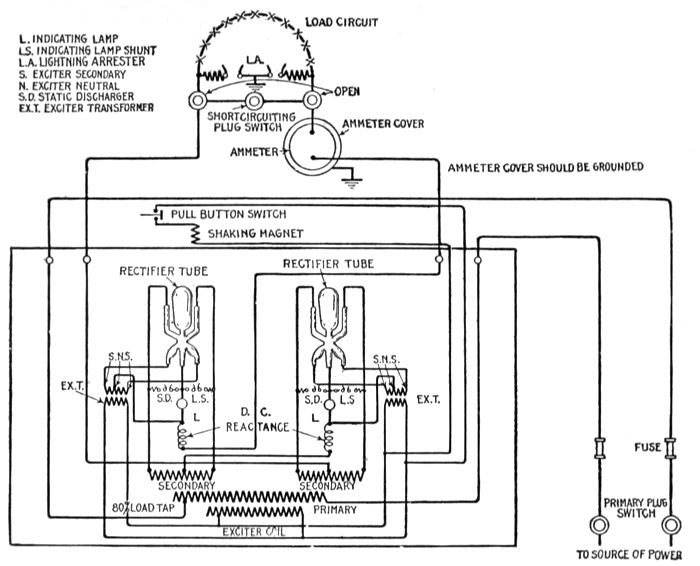
Fig. 2,110.—Diagram showing connections
of General Electric combined
unit mercury arc double
tube rectifier outfit with remote
controlled non-automatic shaking
device.
[Pg 1520]
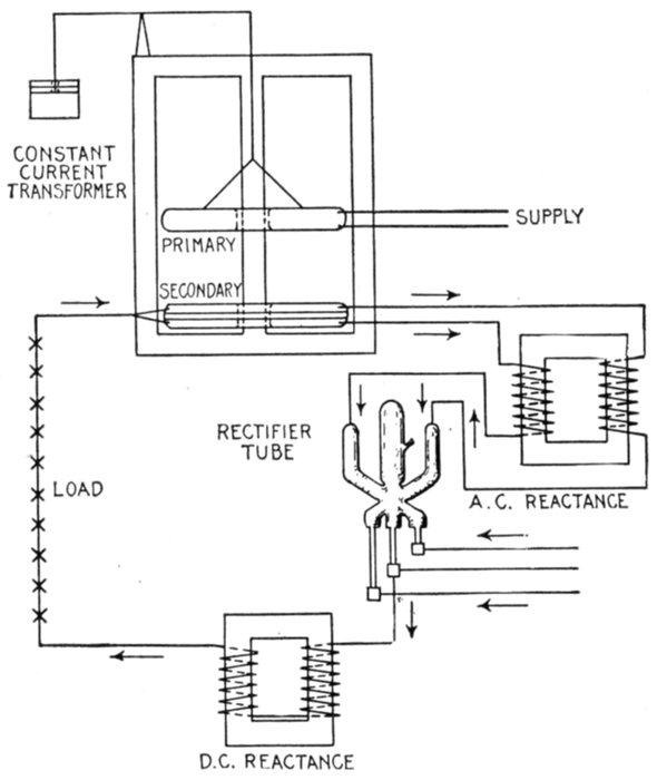
Fig. 2,111.—Diagram showing connections of General Electric series mercury arc rectifier.
[Pg 1521]
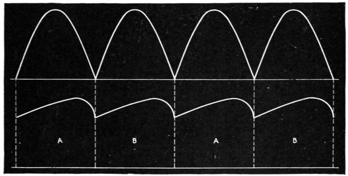
Figs. 2,112 and 2,113.—Diagram of current waves showing effect of reactance coil. If the
alternating current wave could be rectified without the use of the reactance coil, the
direct current produced would consist of a series of impulses which would rise and fall
from the zero line as illustrated in fig. 2,112. The action of the reactance coil not only
maintains the current through the tube while the supply current is passing through
zero, but helps to smooth out the pulsations of the direct current which is passing out
of the cathode terminal of the tube to the batteries, or other direct current apparatus
put in its circuit. The smoothing out effect of the reactance is shown in fig. 2,113. It
will be seen from the diagram that the current does not drop down to zero and the pulsations
of the direct current are greatly reduced. The waves A, A, etc., are from the positive
waves of the alternating current supply, while B, B, are from the negative waves, and together
they form the rectified current, flowing in the same direction to the external
direct current circuit shown at B in the diagram, fig. 2,108.
Ques. How is a mercury arc rectifier started?
Ans. A rectifier outfit with its starting devices, etc., is shown
in figs. 2,114 to 2,116. To start the rectifier, close in order named
line switch and circuit breaker; hold the starting switch in opposite
position from normal; rock the tube gently by rectifier shaker.
When the tube starts, as shown by greenish blue light, release[Pg 1522]
starting switch and see that it goes back to normal position.
Adjust the charging current by means of fine regulation switch
on the left; or, if not sufficient, by one button of coarse regulation
switch on the right. The regulating switch may have to be
adjusted occasionally during charge, if it be desired to maintain
charging amperes approximately constant.
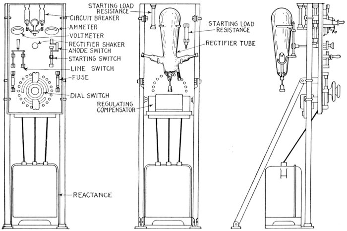
Figs. 2,114 to 2,116.—General Electric mercury arc rectifier outfit, or charging set. The cut shows front, rear, and side views of
the rectifier, illustrating the arrangement on a panel, of the rectifier tube with its connection and operating devices.
[Pg 1523]
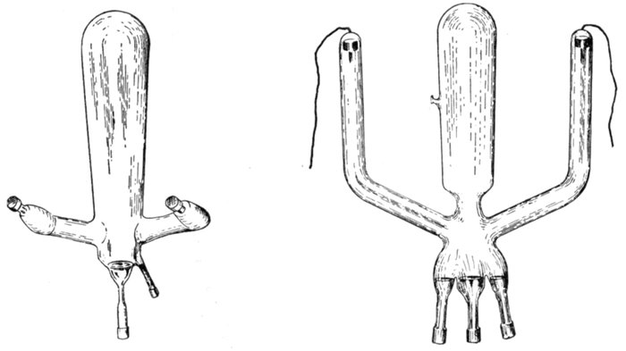
Figs. 2,117 and 2,118.—General Electric mercury arc bulbs or tubes for 200 and 10,000 volt
circuits.
Ques. In the manufacture of rectifiers, could other
metals be used for the cathode in place of mercury?
Ans. Yes.
Ques. Why are they not used?
Ans. Because, on account of the arc produced, they would
gradually wear away and could not be replaced conveniently.
[Pg 1524]
In the case of mercury, the excess vapor is condensed to liquid form
in the large glass bulb or condensing chamber of the tube and gravitates
back to the cathode, where it is used over and over again.
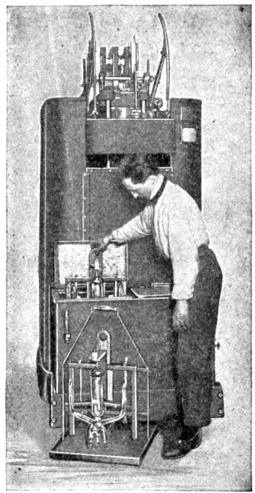
Fig. 2,119.—General Electric series mercury arc rectifier outfit; view showing method of
replacing a tube. The illustration also shows tube carrier and drip tray.
Ques. In the operation of rectifiers, how is the heat
generated in the bulb dissipated?
Ans. In small rectifier sets the heat generated is dissipated
through the tube to the air, and in large tubes such as used in
supplying 40 to 60 kw. for constant current flaming arc lights
operating at 4 or 6.6 amperes, the tubes are immersed in a[Pg 1525]
tank of oil, and cooled similar to the arrangement used for oil
insulated water cooled transformers.
Ques. What results are obtained with oil cooled tubes?
Ans. In practice it is found that the life of oil cooled tubes
is greatly increased and temperature changes do not affect the
ability to start up as in the air cooled tubes.
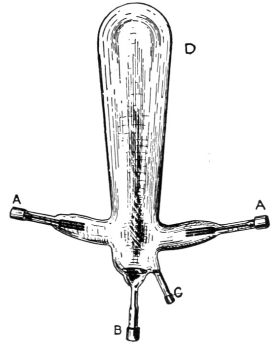
Fig. 2,120.—General Electric 100 volt mercury arc rectifier tube. A,A, anodes; B, cathode;
C, starting anode; D, tube or bulb.
Ques. In the operation of a rectifier, name an inherent
feature of the mercury arc.
Ans. A reverse pressure of approximately 14 volts is produced,
which remains nearly constant through changes of load,[Pg 1526]
frequency, and voltage. Its effect is to decrease the commercial
efficiency slightly on light loads.
Ques. What is the advantage of a rectifier set over a
motor generator set?
Ans. Higher efficiency and lower first cost.
Ques. What is the capacity of a rectifier tube?
Ans. 40 to 50 amperes.
Ques. How is greater capacity obtained?
Ans. When a greater ampere capacity is required, two or
more rectifier sets can be joined to one circuit.
The rectifier may be joined in series for producing an increased voltage
or two tubes can be connected in series in a single set.
Ques. For what service is a rotary converter better
adapted than a rectifier?
Ans. For power distribution and other cases where a great
amount of alternating current is to be converted into direct
current, the rotary converter or large motor generator sets are
more practical.
Ques. For what service is a rectifier especially adapted?
Ans. It is very desirable for charging storage batteries for
automobiles from the local alternating current lighting circuit.
When the consumer installs and operates the apparatus for his own use
and wear, there is considerable saving over motor generator sets because
a small one to two horse power motor generator outfit has an efficiency
of only 40 to 50 per cent. while mercury vapor rectifiers will have from
75 to 80 per cent.
Ques. What precautions should be taken in installing
a rectifier?
Ans. It should be installed in a dry place and care should
be taken to avoid dangling wires near the tube to prevent[Pg 1527]
puncturing. If the apparatus be installed in a room of uniform
moderate temperature very little trouble will be experienced in
starting, while extreme cold will make starting more difficult.
[12]Electro-magnetic Rectifiers.—Devices of this class consist
essentially of a double contact rocker which rocks on pivot
(midway between the contacts), in synchronism with the frequency
of the alternating current, so changing the connections
at the instants of reversals of the alternating current that a
direct current is obtained.
Fig. 2,121 is a combined sketch and diagram of connections
of a type of electromagnetic rectifier that has been introduced
for changing alternating into direct current. The actual apparatus
consists of a box, with perforated metal sides, about
ten inches square and six inches deep. This box contains the
step down transformer P,S,S', and the condensers K and K',
the magnets and contact making device about to be described
being fixed on the polished slate top of the box, exactly as
shown in the figure. The transformer primary winding P
may be connected through a switch s with a pair of ways on
the nearest distribution box, or to a plug connection or lamp-holder,
and the apparatus will give a rectified current of 6 or
12 amperes at 20 volts, according to the size.
S and S' is the secondary winding of the transformer, with
a tapping t midway, joining it to a series circuit containing
two alternating current electromagnets E and E', whose
cores are connected by the long soft iron yoke Y. Pivoted
at P' is a steel bar SB, which is polarized by the two coils
C and C' the current being supplied by a cell A. Fixed[Pg 1528]
rigidly to SB, and moving with it, is a double contact piece CP
with platinum contacts opposite similar ones on the fixed studs
CS, CS'.
CP is flexibly connected through F to one of the direct current
terminals T, to which also are joined up one coating of each
condenser K and K'.

Fig. 2,121.—Diagram showing essential features of Premier Ampero electromagnetic rectifier.
Details of construction and principles of operation are given in the accompanying text.
The other direct current terminal T' is connected to the
center of the transformer secondary at t; and CS and CS' are
respectively joined up to either end of the secondary winding
and to the other coatings of the condensers.
[Pg 1529]
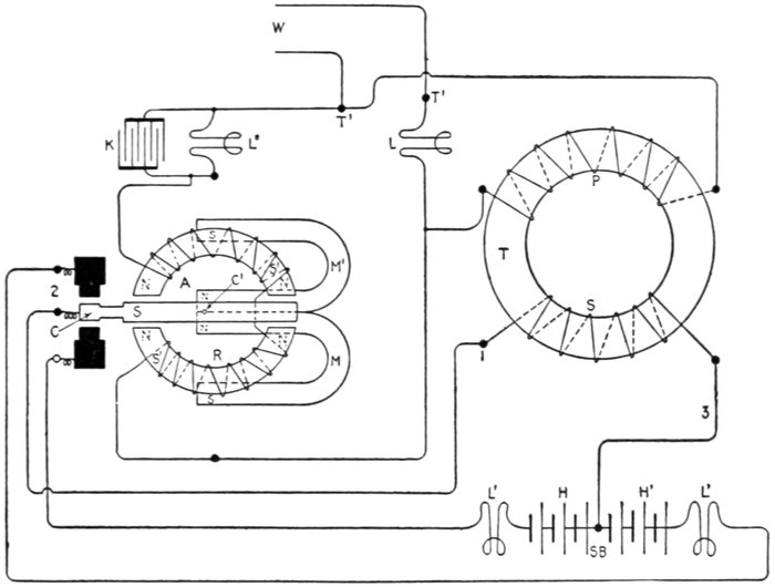
Fig. 2,122.—Diagram of General Electric (Batten) electromagnetic rectifier. It is desirable
for light and occasional service, where direct current is required but only an alternating
supply is available, being used for charging storage batteries, exciting spark coils, performing
electrolytic work, etc. The rectifier consists of a step down static transformer
T, by means of which the circuit pressure is reduced to about 50 volts; also, a polarized
relay R, the contact tongue C of which moves to one side or the other in sympathy with
the alternations of the current in the primary winding P, the secondary current induced
in the winding S being thereby rendered direct in the outer circuit. T', T' are the main
terminals which are connected to the alternating current supply through the wires W.
Lamps inserted at L are used as resistances in the primary circuit, the reduction of the
voltage already alluded to being effected by this means. In charging storage batteries
where a low pressure is required, a lamp (or lamps) should be connected in the secondary
circuit as shown, S B being the storage battery, and L' L' the lamp resistances in series
therewith, the battery has one end of the secondary S connected to its middle. Thus
the alternating current leaving the transformer by the wire 1, passes by flexible connection
2, to the vibrating contact tongue C of the relay, the latter causing the currents
in either direction to flow through the two halves H, H' of the battery, whence the
current re-enters the secondary of the transformer by the wire 3. The soft iron core
of the relay is in two halves S' S' and the armature A, carrying C, vibrates between
their polar extremities. M, M' are two permanent magnets with their like poles together
at the center C' where A is pivoted. Supposing these poles are north as indicated, the
extremities of A will be south. The south ends of M, M being in juxtaposition with
the centers of the soft iron cores S', S' will render their extremities facing the ends of
A of north polarity. The windings on S', S' are connected in series with each other,
and in shunt with P across the main terminals T', T'. Then because of the polarization
of A and S', S', the former will vibrate rapidly in sympathy with the alternations
of the current. K is a condenser shunted by a lamp resistance L", this being found to
improve the working of R.
[Pg 1530]
When the alternating current circuit is broken, the springs
SP, SP, carried by SB and bearing against the adjustable studs,
keep SB, CS and CS'. The apparatus thus acts also as a no
voltage circuit breaker, for should the supply fail, the storage
battery A' under charge will be left on open circuit.
The action of the device is briefly as follows:
Owing to the direct current in the magnetizing coils C and
C' one end of SB will be permanently of north and the other
of south polarity; and since the polarities of the poles E and E'
will alternate with the alternations of the transformer secondary
current, SB will rock rapidly on its pivot, and contact will be
made by turns with CS and CS'.
The purpose of the condensers K and K' is to reduce the
sparking at these points. When contact is made at CS, the
direct current terminals T and T' are connected to the S half
of the secondary winding; and when contact is made at CS',
they are connected to the S' half. Thus a rectified uni-directional
current will flow from T and T', and it may be used to
charge the battery A', work a small motor or for various other
purposes requiring direct current.
When the rectifier is used for charging storage batteries, the
separate cell A may sometimes be dispensed with, the winding
C,C' being connected to one of the cells under charge.
The rectifier is adjusted to suit the frequency of the supply
circuit by altering the distance of the poles of E and E' from
the ends of the polarized armature SB; and also by changing
the tension of SP, SP by means of the screw studs against which
they bear.
[Pg 1531]
HAWKINS PRACTICAL LIBRARY OF
ELECTRICITY
IN HANDY POCKET FORMPRICE $1 EACH
They are not only the best, but the cheapest work published on Electricity.
Each number being complete in itself. Separate numbers sent postpaid to
any address on receipt of price. They are guaranteed in every way or
your money will be returned. Complete catalog of series will be mailed
free on request.
ELECTRICAL GUIDE, NO. 1
Containing the principles of Elementary Electricity, Magnetism,
Induction, Experiments, Dynamos, Electric Machinery.
ELECTRICAL GUIDE, NO. 2
The construction of Dynamos, Motors, Armatures, Armature
Windings, Installing of Dynamos.
ELECTRICAL GUIDE, NO. 3
Electrical Instruments, Testing, Practical Management of Dynamos
and Motors.
ELECTRICAL GUIDE, NO. 4
Distribution Systems, Wiring, Wiring Diagrams, Sign Flashers,
Storage Batteries.
ELECTRICAL GUIDE, NO. 5
Principles of Alternating Currents and Alternators.
ELECTRICAL GUIDE, NO. 6
Alternating Current Motors, Transformers, Converters, Rectifiers.
ELECTRICAL GUIDE, NO. 7
Alternating Current Systems, Circuit Breakers, Measuring Instruments.
ELECTRICAL GUIDE, NO. 8
Alternating Current Switch Boards, Wiring, Power Stations,
Installation and Operation.
ELECTRICAL GUIDE, NO. 9
Telephone, Telegraph, Wireless, Bells, Lighting, Railways.
ELECTRICAL GUIDE, NO. 10
Modern Practical Applications of Electricity and Ready Reference
Index of the 10 Numbers.
Theo. Audel & Co., Publishers.
72 FIFTH AVENUE,
NEW YORK
TRANSCRIBER'S NOTES
Silently corrected simple spelling, grammar, and typographical errors.
Retained anachronistic and non-standard spellings as printed.
End of Project Gutenberg's Hawkins Electrical Guide v. 6 (of 10), by Hawkins

*** END OF THIS PROJECT GUTENBERG EBOOK HAWKINS ELECTRICAL GUIDE ***

***** This file should be named 49252-h.htm or 49252-h.zip *****
This and all associated files of various formats will be found in:
        http://www.gutenberg.org/4/9/2/5/49252/

Produced by Richard Tonsing, Juliet Sutherland and the
Online Distributed Proofreading Team at http://www.pgdp.net


Updated editions will replace the previous one--the old editions will
be renamed.

Creating the works from print editions not protected by U.S. copyright
law means that no one owns a United States copyright in these works,
so the Foundation (and you!) can copy and distribute it in the United
States without permission and without paying copyright
royalties. Special rules, set forth in the General Terms of Use part
of this license, apply to copying and distributing Project
Gutenberg-tm electronic works to protect the PROJECT GUTENBERG-tm
concept and trademark. Project Gutenberg is a registered trademark,
and may not be used if you charge for the eBooks, unless you receive
specific permission. If you do not charge anything for copies of this
eBook, complying with the rules is very easy. You may use this eBook
for nearly any purpose such as creation of derivative works, reports,
performances and research. They may be modified and printed and given
away--you may do practically ANYTHING in the United States with eBooks
not protected by U.S. copyright law. Redistribution is subject to the
trademark license, especially commercial redistribution.

START: FULL LICENSE

THE FULL PROJECT GUTENBERG LICENSE
PLEASE READ THIS BEFORE YOU DISTRIBUTE OR USE THIS WORK

To protect the Project Gutenberg-tm mission of promoting the free
distribution of electronic works, by using or distributing this work
(or any other work associated in any way with the phrase "Project
Gutenberg"), you agree to comply with all the terms of the Full
Project Gutenberg-tm License available with this file or online at
www.gutenberg.org/license.

Section 1. General Terms of Use and Redistributing Project
Gutenberg-tm electronic works

1.A. By reading or using any part of this Project Gutenberg-tm
electronic work, you indicate that you have read, understand, agree to
and accept all the terms of this license and intellectual property
(trademark/copyright) agreement. If you do not agree to abide by all
the terms of this agreement, you must cease using and return or
destroy all copies of Project Gutenberg-tm electronic works in your
possession. If you paid a fee for obtaining a copy of or access to a
Project Gutenberg-tm electronic work and you do not agree to be bound
by the terms of this agreement, you may obtain a refund from the
person or entity to whom you paid the fee as set forth in paragraph
1.E.8.

1.B. "Project Gutenberg" is a registered trademark. It may only be
used on or associated in any way with an electronic work by people who
agree to be bound by the terms of this agreement. There are a few
things that you can do with most Project Gutenberg-tm electronic works
even without complying with the full terms of this agreement. See
paragraph 1.C below. There are a lot of things you can do with Project
Gutenberg-tm electronic works if you follow the terms of this
agreement and help preserve free future access to Project Gutenberg-tm
electronic works. See paragraph 1.E below.

1.C. The Project Gutenberg Literary Archive Foundation ("the
Foundation" or PGLAF), owns a compilation copyright in the collection
of Project Gutenberg-tm electronic works. Nearly all the individual
works in the collection are in the public domain in the United
States. If an individual work is unprotected by copyright law in the
United States and you are located in the United States, we do not
claim a right to prevent you from copying, distributing, performing,
displaying or creating derivative works based on the work as long as
all references to Project Gutenberg are removed. Of course, we hope
that you will support the Project Gutenberg-tm mission of promoting
free access to electronic works by freely sharing Project Gutenberg-tm
works in compliance with the terms of this agreement for keeping the
Project Gutenberg-tm name associated with the work. You can easily
comply with the terms of this agreement by keeping this work in the
same format with its attached full Project Gutenberg-tm License when
you share it without charge with others.

1.D. The copyright laws of the place where you are located also govern
what you can do with this work. Copyright laws in most countries are
in a constant state of change. If you are outside the United States,
check the laws of your country in addition to the terms of this
agreement before downloading, copying, displaying, performing,
distributing or creating derivative works based on this work or any
other Project Gutenberg-tm work. The Foundation makes no
representations concerning the copyright status of any work in any
country outside the United States.

1.E. Unless you have removed all references to Project Gutenberg:

1.E.1. The following sentence, with active links to, or other
immediate access to, the full Project Gutenberg-tm License must appear
prominently whenever any copy of a Project Gutenberg-tm work (any work
on which the phrase "Project Gutenberg" appears, or with which the
phrase "Project Gutenberg" is associated) is accessed, displayed,
performed, viewed, copied or distributed:

  This eBook is for the use of anyone anywhere in the United States and
  most other parts of the world at no cost and with almost no
  restrictions whatsoever. You may copy it, give it away or re-use it
  under the terms of the Project Gutenberg License included with this
  eBook or online at www.gutenberg.org. If you are not located in the
  United States, you'll have to check the laws of the country where you
  are located before using this ebook.

1.E.2. If an individual Project Gutenberg-tm electronic work is
derived from texts not protected by U.S. copyright law (does not
contain a notice indicating that it is posted with permission of the
copyright holder), the work can be copied and distributed to anyone in
the United States without paying any fees or charges. If you are
redistributing or providing access to a work with the phrase "Project
Gutenberg" associated with or appearing on the work, you must comply
either with the requirements of paragraphs 1.E.1 through 1.E.7 or
obtain permission for the use of the work and the Project Gutenberg-tm
trademark as set forth in paragraphs 1.E.8 or 1.E.9.

1.E.3. If an individual Project Gutenberg-tm electronic work is posted
with the permission of the copyright holder, your use and distribution
must comply with both paragraphs 1.E.1 through 1.E.7 and any
additional terms imposed by the copyright holder. Additional terms
will be linked to the Project Gutenberg-tm License for all works
posted with the permission of the copyright holder found at the
beginning of this work.

1.E.4. Do not unlink or detach or remove the full Project Gutenberg-tm
License terms from this work, or any files containing a part of this
work or any other work associated with Project Gutenberg-tm.

1.E.5. Do not copy, display, perform, distribute or redistribute this
electronic work, or any part of this electronic work, without
prominently displaying the sentence set forth in paragraph 1.E.1 with
active links or immediate access to the full terms of the Project
Gutenberg-tm License.

1.E.6. You may convert to and distribute this work in any binary,
compressed, marked up, nonproprietary or proprietary form, including
any word processing or hypertext form. However, if you provide access
to or distribute copies of a Project Gutenberg-tm work in a format
other than "Plain Vanilla ASCII" or other format used in the official
version posted on the official Project Gutenberg-tm web site
(www.gutenberg.org), you must, at no additional cost, fee or expense
to the user, provide a copy, a means of exporting a copy, or a means
of obtaining a copy upon request, of the work in its original "Plain
Vanilla ASCII" or other form. Any alternate format must include the
full Project Gutenberg-tm License as specified in paragraph 1.E.1.

1.E.7. Do not charge a fee for access to, viewing, displaying,
performing, copying or distributing any Project Gutenberg-tm works
unless you comply with paragraph 1.E.8 or 1.E.9.

1.E.8. You may charge a reasonable fee for copies of or providing
access to or distributing Project Gutenberg-tm electronic works
provided that

* You pay a royalty fee of 20% of the gross profits you derive from
  the use of Project Gutenberg-tm works calculated using the method
  you already use to calculate your applicable taxes. The fee is owed
  to the owner of the Project Gutenberg-tm trademark, but he has
  agreed to donate royalties under this paragraph to the Project
  Gutenberg Literary Archive Foundation. Royalty payments must be paid
  within 60 days following each date on which you prepare (or are
  legally required to prepare) your periodic tax returns. Royalty
  payments should be clearly marked as such and sent to the Project
  Gutenberg Literary Archive Foundation at the address specified in
  Section 4, "Information about donations to the Project Gutenberg
  Literary Archive Foundation."

* You provide a full refund of any money paid by a user who notifies
  you in writing (or by e-mail) within 30 days of receipt that s/he
  does not agree to the terms of the full Project Gutenberg-tm
  License. You must require such a user to return or destroy all
  copies of the works possessed in a physical medium and discontinue
  all use of and all access to other copies of Project Gutenberg-tm
  works.

* You provide, in accordance with paragraph 1.F.3, a full refund of
  any money paid for a work or a replacement copy, if a defect in the
  electronic work is discovered and reported to you within 90 days of
  receipt of the work.

* You comply with all other terms of this agreement for free
  distribution of Project Gutenberg-tm works.

1.E.9. If you wish to charge a fee or distribute a Project
Gutenberg-tm electronic work or group of works on different terms than
are set forth in this agreement, you must obtain permission in writing
from both the Project Gutenberg Literary Archive Foundation and The
Project Gutenberg Trademark LLC, the owner of the Project Gutenberg-tm
trademark. Contact the Foundation as set forth in Section 3 below.

1.F.

1.F.1. Project Gutenberg volunteers and employees expend considerable
effort to identify, do copyright research on, transcribe and proofread
works not protected by U.S. copyright law in creating the Project
Gutenberg-tm collection. Despite these efforts, Project Gutenberg-tm
electronic works, and the medium on which they may be stored, may
contain "Defects," such as, but not limited to, incomplete, inaccurate
or corrupt data, transcription errors, a copyright or other
intellectual property infringement, a defective or damaged disk or
other medium, a computer virus, or computer codes that damage or
cannot be read by your equipment.

1.F.2. LIMITED WARRANTY, DISCLAIMER OF DAMAGES - Except for the "Right
of Replacement or Refund" described in paragraph 1.F.3, the Project
Gutenberg Literary Archive Foundation, the owner of the Project
Gutenberg-tm trademark, and any other party distributing a Project
Gutenberg-tm electronic work under this agreement, disclaim all
liability to you for damages, costs and expenses, including legal
fees. YOU AGREE THAT YOU HAVE NO REMEDIES FOR NEGLIGENCE, STRICT
LIABILITY, BREACH OF WARRANTY OR BREACH OF CONTRACT EXCEPT THOSE
PROVIDED IN PARAGRAPH 1.F.3. YOU AGREE THAT THE FOUNDATION, THE
TRADEMARK OWNER, AND ANY DISTRIBUTOR UNDER THIS AGREEMENT WILL NOT BE
LIABLE TO YOU FOR ACTUAL, DIRECT, INDIRECT, CONSEQUENTIAL, PUNITIVE OR
INCIDENTAL DAMAGES EVEN IF YOU GIVE NOTICE OF THE POSSIBILITY OF SUCH
DAMAGE.

1.F.3. LIMITED RIGHT OF REPLACEMENT OR REFUND - If you discover a
defect in this electronic work within 90 days of receiving it, you can
receive a refund of the money (if any) you paid for it by sending a
written explanation to the person you received the work from. If you
received the work on a physical medium, you must return the medium
with your written explanation. The person or entity that provided you
with the defective work may elect to provide a replacement copy in
lieu of a refund. If you received the work electronically, the person
or entity providing it to you may choose to give you a second
opportunity to receive the work electronically in lieu of a refund. If
the second copy is also defective, you may demand a refund in writing
without further opportunities to fix the problem.

1.F.4. Except for the limited right of replacement or refund set forth
in paragraph 1.F.3, this work is provided to you 'AS-IS', WITH NO
OTHER WARRANTIES OF ANY KIND, EXPRESS OR IMPLIED, INCLUDING BUT NOT
LIMITED TO WARRANTIES OF MERCHANTABILITY OR FITNESS FOR ANY PURPOSE.

1.F.5. Some states do not allow disclaimers of certain implied
warranties or the exclusion or limitation of certain types of
damages. If any disclaimer or limitation set forth in this agreement
violates the law of the state applicable to this agreement, the
agreement shall be interpreted to make the maximum disclaimer or
limitation permitted by the applicable state law. The invalidity or
unenforceability of any provision of this agreement shall not void the
remaining provisions.

1.F.6. INDEMNITY - You agree to indemnify and hold the Foundation, the
trademark owner, any agent or employee of the Foundation, anyone
providing copies of Project Gutenberg-tm electronic works in
accordance with this agreement, and any volunteers associated with the
production, promotion and distribution of Project Gutenberg-tm
electronic works, harmless from all liability, costs and expenses,
including legal fees, that arise directly or indirectly from any of
the following which you do or cause to occur: (a) distribution of this
or any Project Gutenberg-tm work, (b) alteration, modification, or
additions or deletions to any Project Gutenberg-tm work, and (c) any
Defect you cause.

Section 2. Information about the Mission of Project Gutenberg-tm

Project Gutenberg-tm is synonymous with the free distribution of
electronic works in formats readable by the widest variety of
computers including obsolete, old, middle-aged and new computers. It
exists because of the efforts of hundreds of volunteers and donations
from people in all walks of life.

Volunteers and financial support to provide volunteers with the
assistance they need are critical to reaching Project Gutenberg-tm's
goals and ensuring that the Project Gutenberg-tm collection will
remain freely available for generations to come. In 2001, the Project
Gutenberg Literary Archive Foundation was created to provide a secure
and permanent future for Project Gutenberg-tm and future
generations. To learn more about the Project Gutenberg Literary
Archive Foundation and how your efforts and donations can help, see
Sections 3 and 4 and the Foundation information page at
www.gutenberg.org Section 3. Information about the Project Gutenberg
Literary Archive Foundation

The Project Gutenberg Literary Archive Foundation is a non profit
501(c)(3) educational corporation organized under the laws of the
state of Mississippi and granted tax exempt status by the Internal
Revenue Service. The Foundation's EIN or federal tax identification
number is 64-6221541. Contributions to the Project Gutenberg Literary
Archive Foundation are tax deductible to the full extent permitted by
U.S. federal laws and your state's laws.

The Foundation's principal office is in Fairbanks, Alaska, with the
mailing address: PO Box 750175, Fairbanks, AK 99775, but its
volunteers and employees are scattered throughout numerous
locations. Its business office is located at 809 North 1500 West, Salt
Lake City, UT 84116, (801) 596-1887. Email contact links and up to
date contact information can be found at the Foundation's web site and
official page at www.gutenberg.org/contact

For additional contact information:

    Dr. Gregory B. Newby
    Chief Executive and Director
    gbnewby@pglaf.org

Section 4. Information about Donations to the Project Gutenberg
Literary Archive Foundation

Project Gutenberg-tm depends upon and cannot survive without wide
spread public support and donations to carry out its mission of
increasing the number of public domain and licensed works that can be
freely distributed in machine readable form accessible by the widest
array of equipment including outdated equipment. Many small donations
($1 to $5,000) are particularly important to maintaining tax exempt
status with the IRS.

The Foundation is committed to complying with the laws regulating
charities and charitable donations in all 50 states of the United
States. Compliance requirements are not uniform and it takes a
considerable effort, much paperwork and many fees to meet and keep up
with these requirements. We do not solicit donations in locations
where we have not received written confirmation of compliance. To SEND
DONATIONS or determine the status of compliance for any particular
state visit www.gutenberg.org/donate

While we cannot and do not solicit contributions from states where we
have not met the solicitation requirements, we know of no prohibition
against accepting unsolicited donations from donors in such states who
approach us with offers to donate.

International donations are gratefully accepted, but we cannot make
any statements concerning tax treatment of donations received from
outside the United States. U.S. laws alone swamp our small staff.

Please check the Project Gutenberg Web pages for current donation
methods and addresses. Donations are accepted in a number of other
ways including checks, online payments and credit card donations. To
donate, please visit: www.gutenberg.org/donate

Section 5. General Information About Project Gutenberg-tm electronic works.

Professor Michael S. Hart was the originator of the Project
Gutenberg-tm concept of a library of electronic works that could be
freely shared with anyone. For forty years, he produced and
distributed Project Gutenberg-tm eBooks with only a loose network of
volunteer support.

Project Gutenberg-tm eBooks are often created from several printed
editions, all of which are confirmed as not protected by copyright in
the U.S. unless a copyright notice is included. Thus, we do not
necessarily keep eBooks in compliance with any particular paper
edition.

Most people start at our Web site which has the main PG search
facility: www.gutenberg.org

This Web site includes information about Project Gutenberg-tm,
including how to make donations to the Project Gutenberg Literary
Archive Foundation, how to help produce our new eBooks, and how to
subscribe to our email newsletter to hear about new eBooks.

![]() by
by


