![]()
![]()
![]()
![]()
![]()
![]()
![]()
![]()
![]()


All my content and ptohos

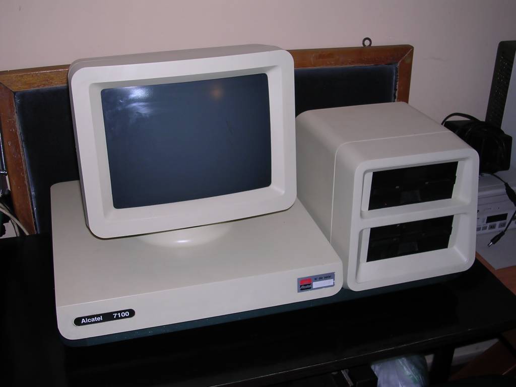
Alcatel 7100
This is a very strange machine. It is built on
Canadian AES 7100 base, but internals are mostly French. It is powered
by Z80 processor and has very big amount of RAM as for 1980s: 256kB. The
only media for it is 5.25" floppy disk, the computer has 2 Shugart
single-sided floppy disk drives. Probably it can run CP/M, but,
according to some sites, the original AES 7100 Model 203 was used only
in word processing.
The base unit consists of a powerful switching PSU for computer and
printer, mainboard, parallel port interface and a strange component
protected with resin (?encoder, Serial ROM?). These parts can be reached
by sliding the tray from the rear. Internals look quite robust as in many
computers from 1980s.
There are significant differences in descriptions of AES 7100 and my
Alcatel. AES probably had RAM expansion sockets, while Alcatel has 256kB
soldered in. There is no information about this protected component, and
in photos of Canadian unit components are not French. Some photos of AES
unit show the unit with different monitor. The "AES" metal plate on the
rear was covered by some sticker, it did not survived the flood but the
glue from it is visible.
Nothing more is known about this machine. There are no photos of working
7100, AES or Alcatel nor system disk images.
According to the
usenet
post, AES machine has been known as Lanier too, but model is not
known.
| Manufacturer | Alcatel |
|
| Origin | France | |
| Year of unit | ~1984 | |
| Year of introduction | ??? | |
| End of production | ??? | |
| CPU | Z80 | |
| Speed | ??4MHz | |
| RAM | 256kB | |
| ROM | 4kB (+4kB character ROM) |
|
| Colors: | Monochrome | |
| Sound: | Beeper | |
| OS: | ??? CP/M ?? ?? Own software? |
|
| Display modes: | ??? Probably text mode display |
|
| Media: | Floppy disk drives (2) |
|
|
|
||
|
Built-in switching power supply |
||
| I/O: | Internal expansion port Printer port |
|
| Possible upgrades: | ??? | |
| Accessories in collection: NONE |
||
| Software accessibility: | Probably impossible |
My unit arrived in a very bad condition. Capacitors in
power supply were blown and a whole machine probably survived flood. The
machine has one floppy drive replaced, but it was probably done when it
was operating, as it was made very professional way. Later, probably
before flood, someone tried to get inside, but failed. Getting
inside this machine is quite difficult. After extensive cleaning and
repairing of power supply I tried to start it.
CRT starts and blinks when machine starts. Speaker beeps constantly and floppy drive tries to read
disk. I think it needs operating system on disk.
| Contents: | Starting | Disassembly | Pinouts | Links |
Starting:
This machine seems to be too simple to display any picture without floppy disk containing operating system. ROMs don't contain any messages too. Unfortunately currently (2016) it is impossible to get operating system or record disks for it.
Disassembly
Mainboard with power supply unit is in a tray which can be slided out the computer. To do it, you need to remove its screws on the rear and bottom of the drawer, as well as in the end of the tray near the front of the computer on the bottom of the unit.
Do not remove smaller screws (2 rows of 4) aligned vertically on both sides of the bottom (if computer is placed CRT facing table). These are for keeping drawer's rails in casing.
To access floppy drives, remove white cover from rear of FDD block. Remove screws from front side (bottom part of the white plastic), then remove screws holding front plastic part inside. Remove the front plastic part. Then you can just unfasten screws holding FDDs and slide them out after removing connectors (power, ribbon cable and grounding wire).
I have no idea how the CRT is kept in place, it was probably built on top of existing computer. White bottom part of CRT is fastened by steel screw-band to the metal base using signal wire shielding. I don't know how to remove it without fully disassembling the CRT, so it may be needed to cut part of shielding.
In every step a bit different screws are used.
Pinouts:
I have only power supply pinouts, here they are:
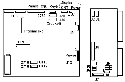
| MAINBOARD: J13 - Power connector, mainboard as shown, top
to bottom: |
J9 - Power connector, ?? 1 - GND 2 - -12V 3 - GND 4 - +12V 5 - GND 6 - +5V J7 - CRT power connector |
| POWER SUPPLY UNIT: J1 - 230V AC input J4 - Computer power supply J5, J6 - FDD power connectors: |
J7 - Power connector for power 1,2,3 - +5V DC 4 - GND 5,6,7 -15V DC 8,9 - GND for +/- 15V 10,11,12 - -15V DC J8 - Auxiliary power? J9 - ?? |

Links:
http://www.computinghistory.org.uk/det/6737/AES-7100-PC-Model-203/
- Canadian machine
http://home.total.net/hrothgar/museum/AES7100/index.html - the only
image which shows partially internals of Canadian machine.
http://www.pcmuseum.ca/galleryview.asp?id=60 - Gallery with one
photo.