![]()
![]()
![]()
![]()
![]()
![]()
![]()
![]()
![]()


All my content and ptohos

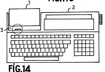
Epson HX-20
| A computer known as the first laptop, but
definitely one of the first portable microcomputers which could
be used from rechargeable batteries. Its story begins in early
1980s. In 1980, inventor received a
French
patent on different forms of portable computers. The system
has been announced in 1981, having release in 1982 and 1983. The computer has everything a typical computer contains: There is a full QWERTY mechanical keyboard, a non-backlit liquid crystal display (4x20 text or 120x32), small dot-matrix printer, in many versions even a microcassette recorder. Everything was powered from the batteries allowing to work around 50 hours with in-ROM BASIC using 16kB of accessible RAM (if no extensions were used). The computer was not much larger than A4 book, and because it was one of first such machines it is sometimes known as the first notebook computer. |
|
|
The CPU were two Hitachi 6301 chips clocked at
0.614MHz. The master processor controlled the keyboard, memory and
display, while slave one driven speaker, printer and cassette
drive. The CPUs exchanged data with 38400bps serial bus. These
strange steps had to be taken (Hitachi 6301 are like Motorola
6809, closer to microcontrollers than microprocessors) to
conserve energy and make the system run from battery. Additional
logic has been made using CMOS chips. |
|
| Manufacturer | Epson |
|
| Origin | Japan | |
| Year of unit | 1985 | |
| Year of introduction | 1981/2 | |
| End of production | 1986? | |
| CPU | 2x Hitachi 6309 | |
| Speed | 0.614MHz | |
| RAM | 16kB | |
| ROM | 32kB | |
| Colors: | 2 | |
| Sound: | Beeper | |
| OS: | Monitor Basic |
|
| Display modes: | Text: 4x20 Graphics: 120x32 Built-in LCD screen only. |
|
|
|
||
| Media: |
ROM cartridge Internal microcassette recorder External tape recorder |
|
|
Power supply: Male DC jack at the computer:
Read further about details! |
||
| I/O: | Serial Tape IO Barcode scanner in RS232C System bus |
|
| Possible upgrades: | Battery replacement, memory by side expansion | |
| Software accessibility: | Possible (dedicated sites) |

|
The addition has a multi-channel digital input, serial output
and additional serial pass-through to connect printer. |
|

| Contents: | Power, battery | Starting | Typical problems | Loading programs | Pinouts | Links |
The power supply is UNREGULATED 6V DC at 600mA with
specific voltage drop when under load. According to
this
page, it has 9.3V when no load and 7.2V when 150mA load.
Because the charging battery makes a natural load which makes this
voltage smaller (around 150mA is a charging current) it is important to
use such voltage.
The computer should not be used without battery, as the
transformer unit will not be loaded enough to make the supply voltage
lower - then, the computer may not regulate voltages properly.
However, it is possible to run it without battery for testing purposes
if you use a regulated power unit scaled at ca. 7V. It must be high
enough not to generate "POWER ABNORMAL" signal (this shuts the computer
down permanently to prevent deep battery discharge, present if battery
voltage is too low) and not too high to make regualtors work right.
More about battery
The battery consists of 4 Sub-C size, 1.2V 110mAh NiCd cells connected
in series. Like these cells used in battery-powered drilling machines.
The common trend in these computers is to replace the old NiCd batteries
with modern cells, like 4 AA cells (for example NiMH). This is not a
good idea. First, let's be honest, this computer has no intelligent
charging circuitry at all, there is just a current limitting resistor
acting as a voltage drop if batteries would take a really big current
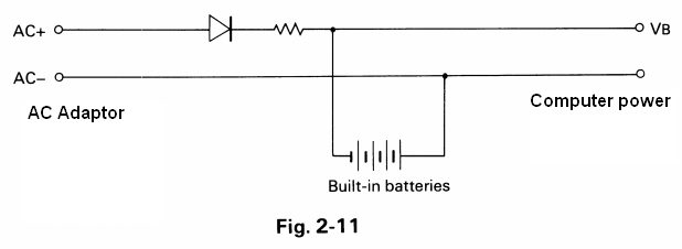
(charging current should be about 150mA). Nothing more. Look at the
schematic presented by the end of this section to see how it looks
like (it's from Technical Reference Manual). AC+ and AC- are + and - of AC adapter, that's how they mark it in
technical manual.
So in result, the battery is not only charged with inappropriate
current, but also for uncontrolled time which dramatically shortens its
lifespan.
I think, but I nevet tried it, that it should be made using a battery
set with own charging circuit, like in one of these ready modules
available in DIY stores. This way the circuit limits the current and the
battery doesn't overcharge.
The computer will not operate if the battery is shorted, wat sometimes
happens. So if the computer during printing shows "CHARGE BATTERY!" and
resets, it means that the batteries need replacing.
The computer needs some time plugged to power adapter to
charge its battery. It was not designed to operate from power supply,
and user must remember to disconnect power supply after 8 hours starting
from the empty batteries, or the power unit will overcharge the
batteries.
For a short time for testing, a voltage around 7-9V may be used, if it
won't blow the internal fuse.
After powering up, the system beeps and displays (if not, try pressing
the Reset button)
CTRL/@ Initialize
1 MONITOR
2 BASIC
In German units there is a paragraph sign (§) instead of
@. If it doesn't go to BASIC or displays garbage, counts more than 2
items or does similar strange things, press CTRL-@ (or CTRL-§ in German
units) to set date, time and clear RAM. You may do it after pressing
Reset or Menu, trying a few times to make the computer catch it in the
right moment (which may be very short).
If it beeps, but doesn't display anything try to tune contrast with a
"VIEW ANGLE" knob.
According to manual (Page 34), DIP switches change character set. The
last one selects between Disk and ROM BASIC.
Typical problems (except battery)
Printer
The printer is a true precision mechanics device. The single motor
operates head, ink ribbon and paper transmission. First, the motor spins
driving cylinder with cam, this cam moves the head back and forth making
a "machine gun" noise. Simultaneously, the same motor spins the gear for
moving the ink ribbon. Every head move back and forth, the pulling rod
advances the paper. The result is printed on 57mm-wide paper
tape.
If it doesn't move its head well, it means that you need to open the
computer (remember not to tear the expansion ribbon cable from the
connector - open the casing in few centimeters, disconnect ribbon and
proceed, pay attention to bottom keyboard ribbons too), then remove the
silver shiny cover from printer and lubricate the leading cylinder and
driving rods. Don't use WD40 for it. WARNING: The head's ribbon cable
breaks very easily, so don't bend it too much.
For the future: The ribbon cartridge is called ERC-09.
Microcassette recorder
While the printer was a precision mechanics, this is even more complex.
The main motor has magnetic tachogenerator to coordinate speed and
counter. Additional motor moves the head to tape using the screw thread
mechanism. This way, the recorder can operate back and forth by control
only with software.
A typical fault is fatigue of a belt which transfers rotation from motor
to the mechanism. This is a piece of precise mechanical part, so don't
use excessive force here. In my unit, unfortunately I had to re-work one
bolt's head to unscrew it.
First of all, the belt: 50mm in diameter, 1x1 or 0.8x0.8mm square.
| How to replace the belt: 1. Remove two screws and the rear/bottom cover of tape recorder. 2. Remove bolts holding the circuit board in place. The long bolt at the upper part near motor has a distance tube under the board, don't loose it, don't install distance tubes in places of another tubes! I use labelled boxes to temporarily store these bolts and tubes during repair in removing order. 3. Carefully move the board downwards (seeing the recorder motor upwards, connector to the right) to see the motor's part. Be careful of the wires! Remove two bolts holding the speed detector in place and remove it taking care about 2 distance tubes under (the proper service name for this round piece is "FG yoke assembly"). Now you can remove belt from the motor. 4. Having the speed detector hanging on the cables, you can move the board to the sides enough to remove bolts locking the aluminum piece holding the big, brass wheel and smaller plastic wheel (using flat spring) in place. One bolt, then PCB goes to the other side and the second one. Take a photo or note about wires soldered to the board, which one goes where. You may need it when one breaks. |
|
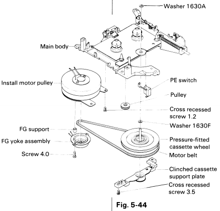
5. Remove this aluminium part (service name: Clinched
cassette support plate) holding brass wheel (Pressure-fitted
cassette wheel), taking care not to loose bolts and wheels.
6. Remove the old belt from wheels. Replace the belt, Check does it run
smoothly. The belt should go from the motor parallel to the connector
side, then to the brass wheel, then it should go back to the motor,
touching the smaller wheel (Pulley) - the small wheel should be
outside of the belt's loop.
7. Replace the aluminum part, fasten the bolts.
8. Clean the rotating magnet and the sensor using soft brush.
9. Replace the speed sensor. Restore distance tubes and bolts. Check the
cylindrical magnet by rotating the brass wheel and observing does the
motor shaft run inside speed sensor - it should not scratch the detector
during spinning and it should spin without problems. If it gets stuck -
move the sensor a bit to center it. Repeat until it works (requires more
time if bigger force was used to remove bolts, be patient here).
10. If any wires fell off the board during speed sensor alignment, now
its time to resolder them.
11. Replace PCB and its bolts with distance. Two smaller distances may
require to be glued to the PCB (use very small amount of a weak glue -
this is temporary) to be installable easier.
12. Close the casing.
Loading programs
BASIC programs are usually distributed by text. It can
be fed to the computer using serial port by rs232 cable. Programs in
machine code are very rare and sometimes distributed on the Internet
with BASIC loaders.
HXTape is a tool to make
tapes waves under Linux, I haven't tested it and it seems that it
requires... PHP. Generally tapes, because they are micro-cassettes, are
recorded in a computer as it's harder and harder to get decks (usually
portable) for them.
Driving the cartridge-type tape recorder is purely automatic,
program-based. There is a built-in "tape recorder mode", press Ctrl-PF1
to get to it. The screen will show tape counter position. Then:
PF1 - Fast forward
PF2 - Slow forward
PF3 - Stop
PF4 - Rewind
PF5 - Exit this mode.
Like in a sticker under PF keys. You can also use WIND command to rewind
tape.
The saving is made by
SAVE "PROGRAM"
and it saves instantly. If the floppy disk is conencted,
it is saved on floppy, then microcassette, and if it's not found,
external cassette output. The name mustnot contain characters: . / , ( )
- the dot may happen once like extension separator.
Loading:
Just LOAD loads the first BASIC program from microcassette, or ROM
cartridge if present. It is also possible to look for program:
LOAD "PROGNAME"
To load from other device, you can make the "device;
program name" notation, while devices are CAS0 (microcassette), CAS1
(external tape), PAC0 (ROM cartridge), A, B, C, D (disk drives).
To print something on the printer, use LPRINT command.
Loading from PC's serial port
Loading from RS232 port is useful when transmitting programs from the
PC.
Here is the way to do it the most simple way, but it's a bit slow. There
are other methods, like using additional flow control wires (a
full cable) or with internal loops in PC side of serial port. Making
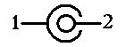
the cable. 3 wires: GND, Tx and Rx. You can use 5-pin DIN plug, only 3
pins are used. Warning: Pinout belo shows connectors at the computers,
so you need a male DIN8 (or even DIN5) plug and female 9-pin plug for
serial port. The pins should correspond to these, i.e. pin marked as 1
on the male DIN plug should not fit to pin 3 in this picture. If
in doubt (because Epson manuals show pin numbers both in plugs and in
connectors in different places) - check in which pin the GND is.
| Connectors at the computers! | ||
 |
 |
Epson->PC |
| Epson RS232C | PC COM port | |
| 1 | 5 | GND |
| 2 | 2 | Tx->Rx |
| 3 | 3 | Rx->Tx |
In the PC, configure the terminal program (e.g. Minicom or WIndows'
HyperTerminal) to the proper serial port, baud rate, parity and stop
bits. Do not use any handshaking. Now the most important parts: Loading.
The command for loading is:
LOAD "COM0:(BLPSC)"
Filling the BLPSC:
B is a number meaning speed:
0 - 110bps, 1 - 150bps, 2 - 300bps, 3 - 600bps, 4 - 1200bps, 5 -
2400bps, 6 - 4800bps. A very safe, but slow option is 300bps.
L is number of bits, 7 or 8.
P is parity: N (none), E (Even) or O (Odd)
S is stop bits, 1 or 2.
C determines state of CtS/RtS, DSR and CD lines. For example is
"B" ignoring CtS and CD, using DSR, RtS (high level), F ignores
everything, only notifies the system by high level on RtS.
So:
LOAD "COM0:(28N1F)"
will load 300bps, 8-bits, no parity, 1 stop bit,
ignoring data lines.
After confirming the command, order PC terminal program to send text
file with BASIC code. After the file is sent, press the BREAK on the
computer and LIST newly loaded program. You can use it or save to
cassette.
The exact tables of characters in BLPSC is shown in
this archived page.
Pinouts:
|
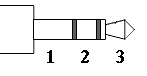
RS-232C port:
|
Serial port:
|
Barcode reader port:
1 - GND |

WARNING: According to the schematic, POUT is output while PIN is input. According to the Technical Reference manual (Section 2.2.2), it's opposite. In cable connecting two HX-20s they're crossed.
Links:
http://web.archive.org/web/20070926235927/http://www.epson.com/cgi-bin/Store/support/supDetail.jsp?BV_UseBVCookie=yes&oid=14492&infoType=Doc
- Epson's support, guides and manuals.
http://web.archive.org/web/20160313142222/http://classway.com/hx20/index.html - HX-20 Enthusiast's page.
http://oldcomputers.net/hx-20.html - In collection, description.
https://fjkraan.home.xs4all.nl/comp/hx20/ - In collection, some
handy tips for running HX-20, how to dump ROMs etc.
http://electrickery.xs4all.nl/comp/hx20/doc/index.html - PDF
documentation of Epson HX-20.
http://www.ganjatron.net/retrocomputing/epson-hx20/index.html -
Description and advertisements.
http://web.archive.org/web/20090805173203/http://www.geocities.com/abcmcfarren/hx20/hx20.htm
- programs in BASIC as well as interface cable schematic, plus
information how to load/save to RS232 port using terminal. Additionally
memory map, character table and system ROM partitioning, opcode list.
http://web.archive.org/web/20140228044441/http://www.wickensonline.co.uk/hx-20/index.html
- Programs and information
http://hx20.jatman.uk/ - More
information on a HX-20 in a specific application.
http://www.atarimagazines.com/creative/v9n3/101_Epson_HX20_computer.php
- Review from Creative Computing, March 1983.
http://bahamas.gestalter.at/hx20/ - Some photos of RAM-upgraded
units, Software for download.
http://www.zock.com/8-Bit/D_HX20.HTML - German description with
emulator screenshots.
http://frigolit.net/projects/hxemu - HX-20 emulator project. At
least works (builds) on Linux.
http://takeda-toshiya.my.coocan.jp/ - eHC-20 emulator. To download
visit eHC-20 page and "Common source code archive", then get binaries or
sources
http://web.archive.org/web/20150524014207/http://www.schwaben.de/home/glassix/HX20schnitt.htm - Pinouts.
http://web.archive.org/web/20150323081245/http://efb-1.de/c_hx20.htm
- Photos e.g. of display output on monitor.