![]()
![]()
![]()
![]()
![]()
![]()
![]()
![]()
![]()


All my content and ptohos

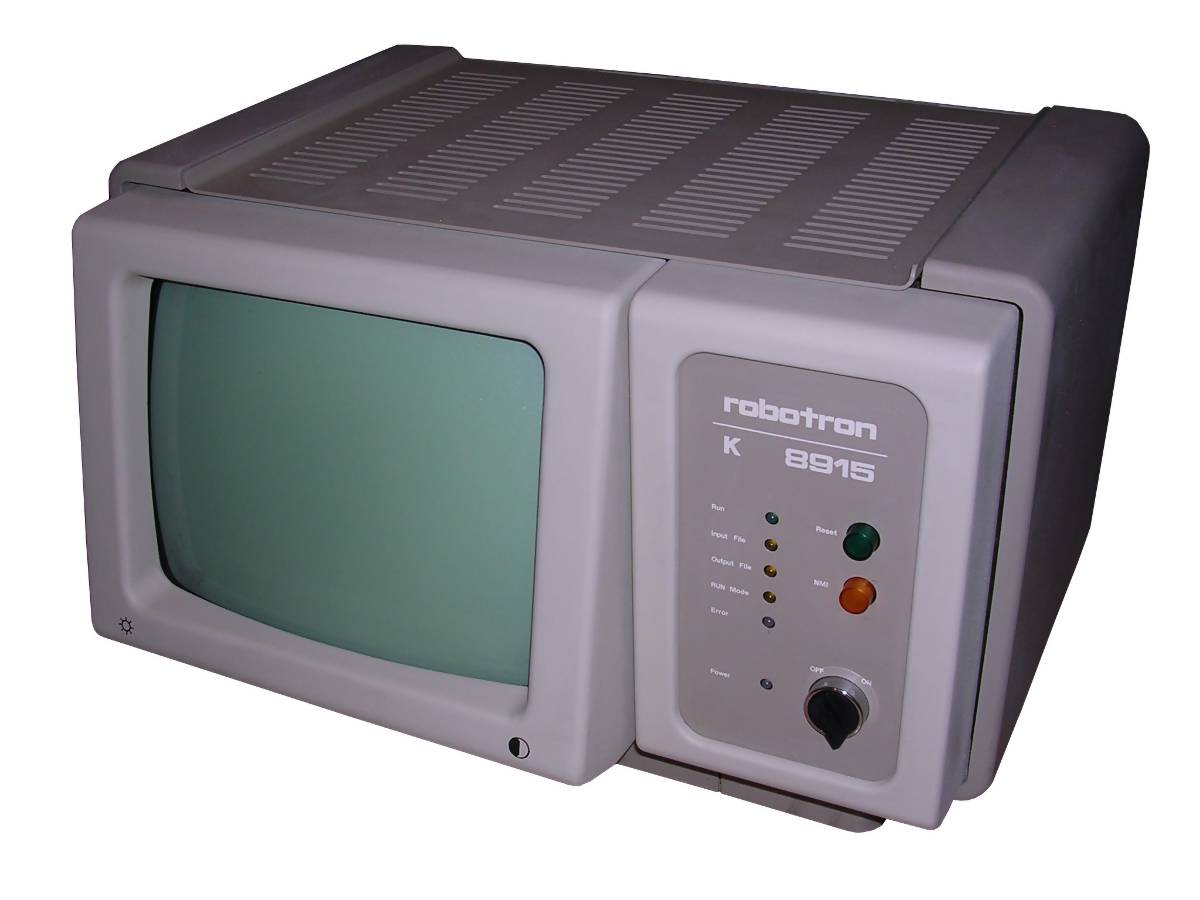
Robotron K8915
Not much is known about this computer, in some pages
described as terminal. I think that this casing was used in one or the
other, maybe using only different ROMs. It is definitely Z80-based CP/M
(Robotron SCP) machine with external 8" or 2x5.25" drives.
Contrary to older Office Computer A5120, this machine is very compact -
there is a CRT, control panel, board cage behind it and that's all.
Power supply, although still made of blocks, lacks stand-by unit (that's
why there is a big power switch in front) and fan. It was based on
components of K1520 microprocessor system developed ca. 1978 and applied
(among some industrial computers) in A5120. And although K8915 looks
like A5120's next version and was probably designed as successor, both models were manufactured simultaneously
for some time (my A5120 is from 1989).
Inside, there is a set of printed circuit boards responsible for
different functions: CPU board, RAM (later incorporated to CPU), serial
I/O board with keyboard (IFSS current-loop port, like in A7100/7150),
video board pretending a terminal for CP/M, as well as floppy drive
controller and, in some rare units, hard disk controller boards while
20MB hard disk was located in computer's base where in A5120 power
transverter/power converters were installed.
These machines also had their ROM improved enough to initialize CRT and
perform a power-on self test by itself. A5120 even didn't cleared its
CRT while more compact PC1715 had no CRT routines, so CRT had to be
initialized from disk.
There were at least 4 versions of this computer not counting terminal.
Early, with magnetic tape reader and KOBRA operating system, later one
with 8" drive, "old" brown unit with 5.25" drives and newer ones - with
gray housing and flat keyboard. These last units had 128kB of RAM on CPU
board.
Robotron manufactured their hardware the way that it fits physically
quite well - on top of A5120 you can put its keyboard or printer
(however, newer model), in this model you can put K6313 printer, but I
don't recommend it as there are quite important vent holes.
| Manufacturer | VEB Robotron, Zella-Mehlis |
|
| Origin | East Germany | |
| Year of unit | 1990 | |
| Year of introduction | 1986? | |
| End of production | 1990? | |
| CPU | Z80 | |
| Speed | 2.5MHZ? | |
| RAM | 128K | |
| ROM | 8kB | |
| Colors: | 2 | |
| Sound: | Beeper in keyboard? | |
| OS: | SCP (CP/M Clone) KOBRA (?) KOKOS (?) |
|
| Display modes: | Text: 80x24. Built-in monochrome green CRT display unit. | |
|
|
||
|
|
||
| Media: | External 2x 5.25" floppy disk drive | |
|
Power supply: |
||
|
Built-in switching power supply givnng +/-5V and +/-12V directly to bus. |
||
| I/O: | External FDD connector IFSS (serial current loop) for keyboard. Parallel port? Serial ports (2) |
|
| Possible upgrades: | Not known, but possible. | |
| Software accessibility: | ?CP/M? |
My unit is a late one with serial number 9999, manufactured in 1990. Most parts are German or western, although few Soviet chips are present. I don't have keyboard for it (the K7672, like for A7100/7150). It looks like some of 16 RAM chips require replacing as it displays "RAM F" message, in which "F" seems to be for "Fault" or "Fehler".
| Contents: | Starting, disassembly | PCB scans | Recording media | Links |
Starting:
Machine boots to ROM. In the bottom line of screen, power-on self test messages are shown. Generally, "F" means fault. Then it tries to boot OS (e.g. SCP - CP/M clone) from floppy.
DISASSEMBLY:
To get into main power fuses, you have to loosen two screws holding rear
panel of the base at its bottom, then slide it paying attention for
power cable. Look to the right. Deeper, there is a AC electrolytic
capacitor. If your Robotron blows fuses, check does it work without this
capacitor :).
Keyboard is usually connected to the topmost connector (the only DB9) on serial board, yet I don't have pinout and I'm not sure about its pinout compatibility with A71x0. These computers were installed by technician in operating place so detaching keyboard/disk drive was not so simple.
Removing of main rear cover: Two screws at the
bottom, open rear upwards, pull downwards, it should separate.
To remove boards, loosen two screws on the upper side of PCB cage,
another two in lower side, slide and remove locking metal bars. Boards
go off hard, this is normal in these systems.
Power inverter boards are easier to work with as they have small metal
"locks" for putting in and out. Remember that in most cases slots are
not easily interchangeable as connections in wire-wrap bus are
different.
Removing top cover: Remove rear cover, then topmost screw, pull
the cover and lift off.
This computer is made the way that screws should stay in their casing
parts (there are an elastic washers on them).
Power supply unit
...is much simpler than the one in A5120. 12V block is behind CRT, while
5V in the same bay as PCBs. Below it, there are two modules, one for
controlling power and releasing CPU from reset state, the second ones
contains two switching converters which make negative voltages. This
board also has LEDs for different voltages to quickly evaluate does it
work at all. Here, PSU power blocks are not chained and they start
together. The first board, containing RESET electronics, has also
connector which can be used to take 5V and 12V from it. It is protected
by fuses on board.
PCB Scans:
| Description | Component side | Solder side |
| Board: 045-8762 Function: CPU, RAM, ROM Ports: None |
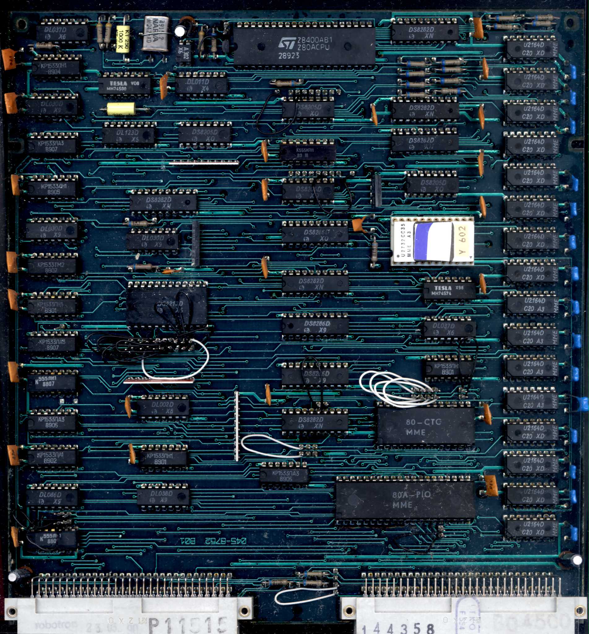 |
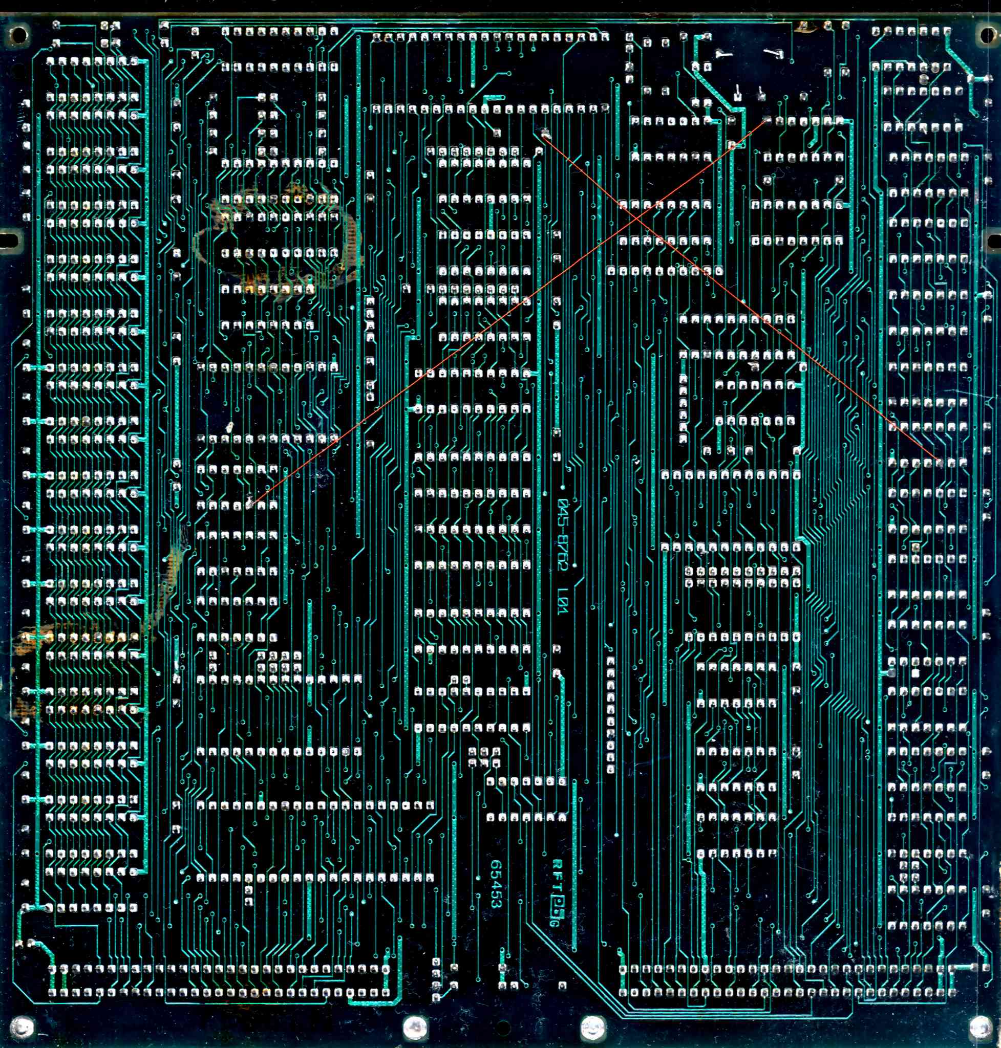 |
| Board: 045-8778 Function: Graphics board Ports: Display output |
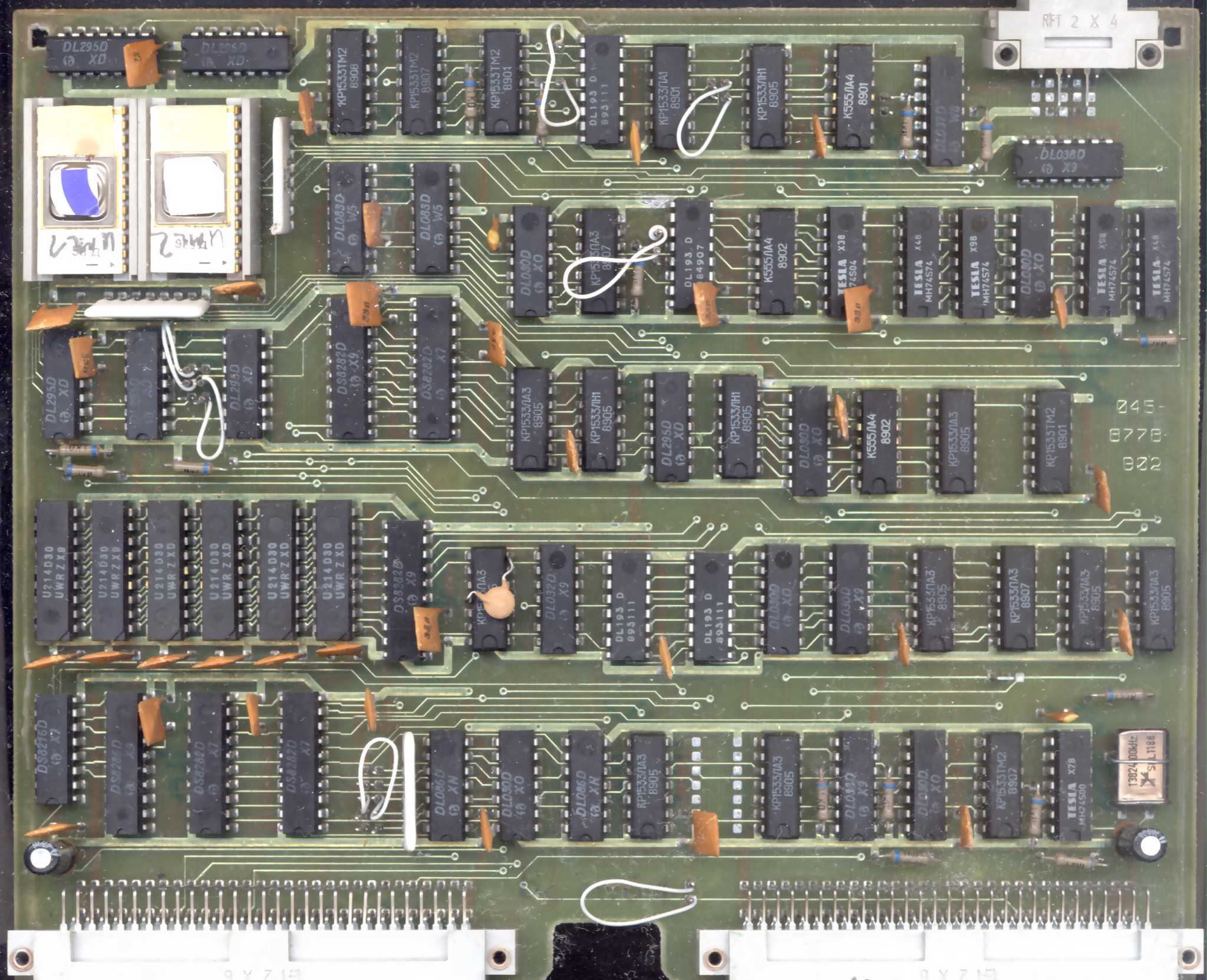 |
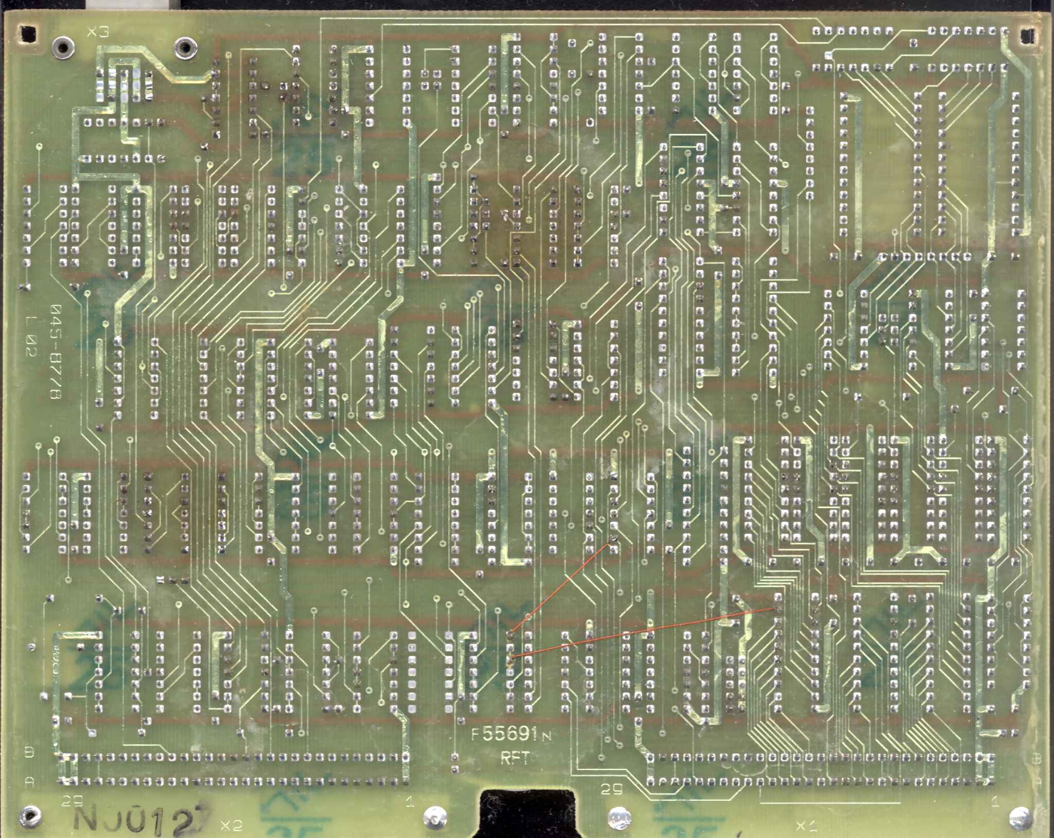 |
| Board: 045-8390 Function: Floppy disk drive controller Ports: Floppy connector |
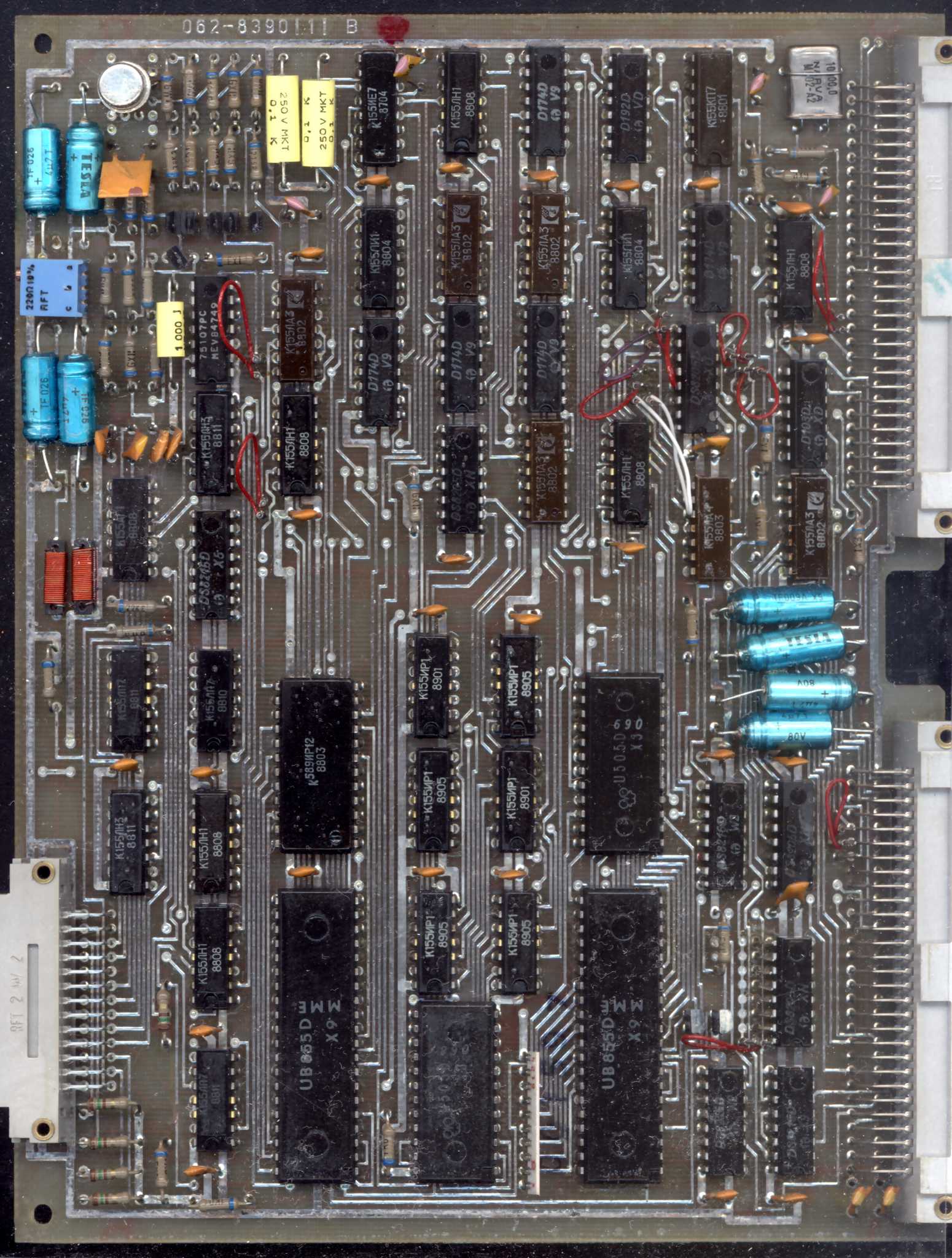 |
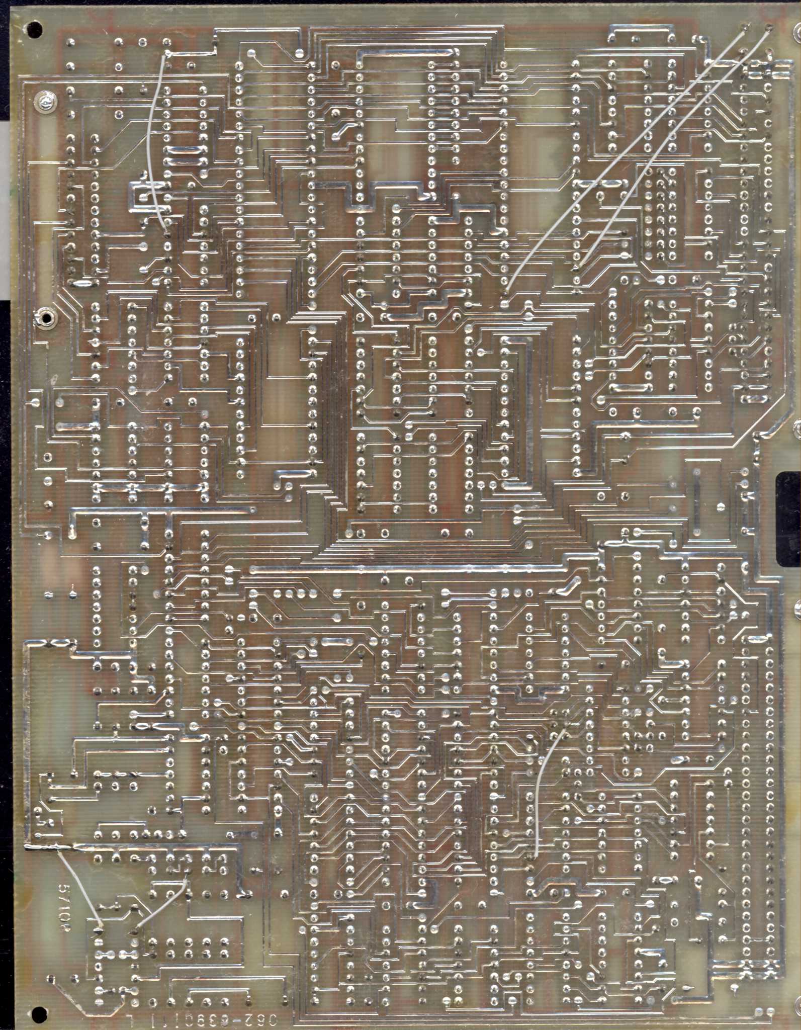 |
| Board: 045-8732 Function: Keyboard/ports controller Ports: Keyboard (DB9), Serial ports, parallel port. |
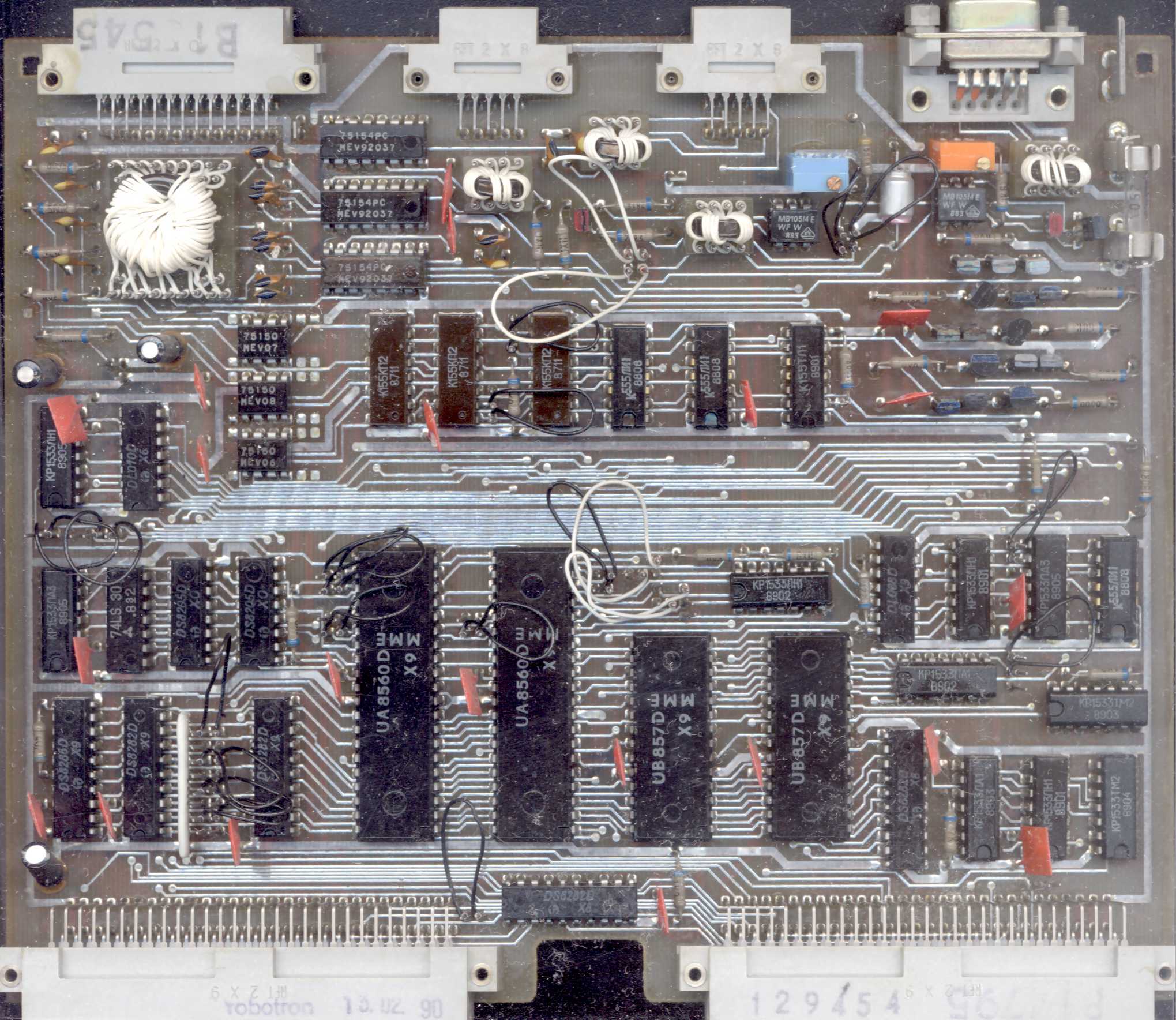 |
 |
Recording media
Currently the floppy standard (geometry) seems to be unknown. Teledisk images should do their job.
Links:
http://www.robotrontechnik.de/index.htm?/html/computer/k8915.htm -
Description in German.
http://www.robotron-computermuseum.efb-1.de/c_k8915.htm - Photos of
a complete set!
http://www.computermuseum-muenchen.de/computer/robotron/k8915.html -
Technical parameters in Computer Museum.
https://www.iee.et.tu-dresden.de/~kc-club/09/RUBRIK37.HTM - Boot
disk for HDD-version
http://www.tiffe.de/Robotron/K1520/K8915/ - incomplete schematics
http://www.tiffe.de/Robotron/K8915/Schaltungsunterlagen/ -
Schematics, second part
http://web.archive.org/web/20040202064844/http://www.kc85.de/Service/Dokus/K8915schaltpl.ZIP
- another part of schematics.
http://www.tiffe.de/Robotron/K8915/ - some ROM dumps
https://archive.org/details/robotron_k8915-mk-sw-ekg - Magnetic tape
I/O documentation?
https://archive.org/details/robotron_k8915scp-doku1 - SCP system
documentation.
Part 2.
Part 3.
Mirror
WARNING: Schematics are for different versions of this
machine. Documentation is in German!.