![]()
![]()
![]()
![]()
![]()
![]()
![]()
![]()
![]()


All my content and ptohos

Tesla PMD 85 (PMD 85-3)
PMD 85 is a computer designed by Engineer's Roman
Kišše team. It was produced in Tesla Piešťany. Mainly used in schools in
Slovakia, as teaching aid (Information Technology). Many interfaces of
this computer shown it also good to teach Automation and to control
industrial machines. In today's Czech Republic IT was taught mainly
using IQ151 computers.
PMD 85 was continuation of PMD computer series: starting with PMD 81
(not much popular because of high price and lack of software), PMD 83
(not much popular because of poor performance, lack of software and
keyboard made of telephone keys). This telephone keyboard survived to
PMD 85-1 model. In 85-2 it was replaced by something a bit better (yet
the keys are a bit small to type quickly from the first try).
PMD 85-2 had better keyboard and it could be left running for longer
than first version (less heating components).
PMD 85-2A had 64K of RAM.
PMD 85-3 was another step forward - Mainly the same as 2A, but less
overheating, it could run for hours. It had much better switching power
supply with last-stage linear regulation. Engineers added more ROM
making Monitor program better, yet incompatible (compatibility mode was
included).
In Didaktik Skalica, Didaktik Alfa and Beta computers - clones of PMD,
were produced.
| Manufacturer | Tesla |
|
| Origin | Czechoslovakia (Slovakia) | |
| Year of unit | 1988 | |
| Year of introduction | 1985 | |
| End of production | 1989 | |
| CPU | 8080 | |
| Speed | 2MHz | |
| RAM | 48K/64K | |
| ROM | 8K | |
| Colors: | 4 | |
| Sound: | Beeper | |
| OS: | Monitor Basic Pascal |
|
| Display modes: | Text: 25x48 Graphics: 288x256 |
|
|
|
||
|
|
||
| Media: |
ROM cartridge External tape recorder |
Power supply: |
|
Male 5-pin DIN at the computer.
P.S. The pinout etched on PSU case is pinout of INNER soldering fields (not the same in all models, some are different than these markings), NOT pinout of DIN plug. |
||
| I/O: | Serial Tape IO RF output Luminance video IMS-2 (IEE488 merely compatible) Two parallel ports System bus ROM expansion |
|
| Possible upgrades: | Not known | |
| Software accessibility: | Possible (dedicated sites) |
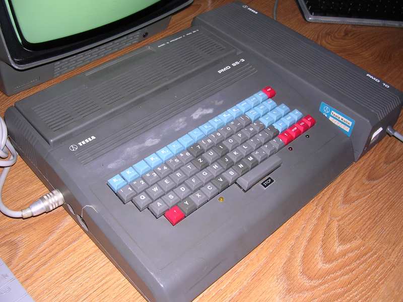

My unit was heavily used in some factory, where it was
driving SUF16CNC numerically-controlled metal milling machine. It has
markings from Tesla Kolin (Czech Republic), probably the machine was
used there.
Photo on this page shows it as it came. It has been restored a bit: the
huge crack near display connector has been chemically repaired.
Unfortunately these stains above K-keys are unerasable.
| Contents: | Starting | Recording media | Joystick | Pinouts | Links |
Starting:
First thing: Reset is Shift+RST.
If no cartridge is in computer, it'll boot to Monitor. This program allows simple memory manipulation and IO.
Loading binary (not Basic, Pascal etc.) program from
tape requires to switch to Monitor. To do it from BASIC,
press Shift-RCL.
If required, PMD 85-2 mode may be switched in -3 version by typing:
JUMP FFF0
Now loading command should be used (instead of 00, use number shown by Emulator's Tape Manager, usually 00):
MGLD 00
After program loads, use JUMP to run program:
JUMP 1234
Where 1234 is program's loading address - every program has its own one. To determine it, try to load PTP in emulator and see "starting address" of file.
Loading from BASIC is simpler:
LOAD 0
Now play tape. It loads... Should display program's name.
RUN
Loading BASIC program from ROM cartridge:
If a BASIC program is placed in cartridge after BASIC iterpreter, you have to use Basic's
ROM statement:
ROM 0
to run first program after BASIC.
Recording media
You can play PTP tape images by sound card using PMD-85 emulator's tape manager - just click a speaker button.
Better way is to use PTP Manager - it can also read PTP from data played to sound card input.
Installing joystick:
Schematic is copied from program accessible here:
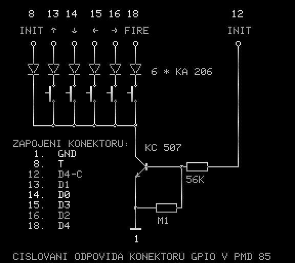
You must connect this to GPIO connector, pins are
designated on drawing. See pinouts for exact pin numbering. Remember
about ground wire, pin 1 at the bottom of picture.
For KC507 you can use BC167, BC182 or BC237. For KA206 use normal
1N4148.
Pinouts:
Let's begin with the simple things. Connectors in
PMD are not labeled any way, so we need to explain what is where. We
will start on the left side of the computer:
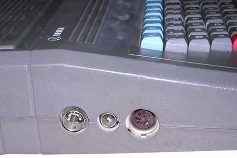
The male DIN connector is power supply connector. Small one is RF
output for connecting TV, the last one, female DIN5, is video output.
Video connector:
|
|
| 1 - Composite sync 2 - GND 3 - Green/Luma 4 - Red 5 - Blue |

I could not get RGB from it. The fastest way to
get any picture is connecting grounds and pin 3 to composite input
of the monitor.
Here's the rear connector:
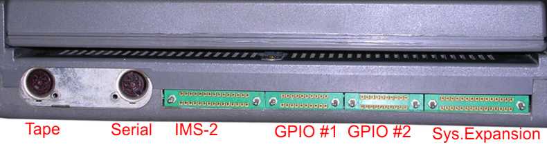
Tape connector:
|
|
| 1 - input 2 - Ground 3 - Output 4 - n.c 5 - n.c |
Serial connector (V.24):
|
|
| 1 - Data IN+ 2 - GND 3 - Data OUT+ 4 - Data IN- 5 - Data OUT- |
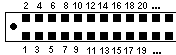
IMS-2 (more or less IEE488 compatible):
|
|
|
| 1 - n.c 2 - /NRFD 3 - DAV 4 - n.c 5 - /NDAC 6 - n.c 7 - GND 8 - GND 9 - n.c 10-REN 11-SRQ 12-D3 13-EOI 14-D2 15-n.c |
16 - ATN 17 - n.c 18 - D1 19 - n.c 20 - IFC 21 - D0 22 - D7 23 - D6 24 - n.c. 25 - D5 26 - D4 27 - n.c. 28 - n.c. 29 - n.c. 30 - n.c. |
GPIO (Parallel port) (Port 2):
|
|
|
| 1 - GND 2 - INV1/OUT 3 - INV2/IN 4 - INV2/OUT 5 - INV1/IN 6 - INV3/OUT 7 - INV3/IN 8 - INIT 9 - PC3 (PC7) 10 -PC2 (PC6) |
11 - PC1
(PC5) 12 - PC0 (PC4) 13 - PB1 (PA) 14 - PB0 (PA) 15 - PB3 (PA) 16 - PB2 (PA) 17 - PB5 (PA) 18 - PB4 (PA) 19 - PB7 (PA) 20 - PB6 (PA) |
Inv are normal logic inverters.
System bus expansion:
|
|
|
| 1 - GND 2 - -5V (+12V in 85-1) 3 - BA6 4 - BA3 5 - BA2 6 - BA5 7 - BA4 8 - BA0 9 - BA1 10 - BA7 11 - Gate 1 (8253) 12 - Out 0 (8253) 13 - Gate 0 (8253) 14 - Out 1 (8253) 15 - INT |
16 - Clk 0 (8253) 17 - IOREAD 18 - DB5 19 - /RESET 20 - DB6 21 - /Fi2 (TTL) 22 - DB7 23 - IOWRITE 24 - DB3 25 - DB1 26 - DB2 27 - DB0 28 - DB4 29 - +5V (-5V or nc in 85-1) 30 - +12V (+5V or nc in 85-1) |
Don't trust these voltage pins! Some schematics have them, some units don't or they're re-aligned!
ROM cartridge connector:
|
|
|
| 1 - DB7 2 - INTE (?) 3 - DB6 4 - /INTR 5 - DB5 6 - /Fi2 (TTL) 7 - DB4 8 - A2 9 - DB3 10 - A3 11 - DB2 12 - A4 13 - DB1 14 - A6 15 - DB0 |
16 - A7 17 - /RESET 18 - A1 19 - /IOWRITE 20 - A0 21 - A5 22 - /IOREAD 23 - +12V 24 - +12V 25 - -5V 26 - -5V 27 - +5V 28 - +5V 29 - GND 30 - GND |
Links:
http://www.schotek.cz/pmd/ -
Technical info, ROMs, simple emulator
http://pmd85.borik.net - The best
emulator, games, ROMs, donwloads
https://github.com/jose1711/simpmd - Emulator for Linux
OS
http://pmd85.topindex.sk/ -
PMD-85 emulation using Atmega processor.