![]()
![]()
![]()
![]()
![]()
![]()
![]()
![]()
![]()


All my content and ptohos

Signal Sintez 2
| A Soviet/Moldovan ZX Spectrum clone sold as gaming console in early
1990s. The first version of Sintez was made as modification of a
well-tested ZX clone design sometimes called "Leningrad" as
some
popular Soviet ZX Clones were made under this name, yet other clones
used this design too and the mainboards were sometimes built in homemade
housings. However, not many first Sintez machines have been made by
Signal plant in Cisinau. The next one, Sintez M, was re-designed to use
available components and reduce number of chips. Sintez M was modified
by "Interkomplex" in Moscow in late 1980s. If you got one of these, prepare TTL probe as it may
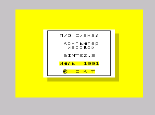
suffer different IC faults. Finally Sintez 2 was a re-design loosely based on original Sintez computer, designed probably near 1989 or 1990 by someone signed as "TERMINAL" - this signature is visible on PCB as well as in demo software. |
|
| It was manufactured by Signal plant,
and it was made in relatively large quantities as for their
conditions. Computers were
manufactured until ca. 1993 (after Moldova became independent country),
however in 1990s not many users were interested in Spectrum clones and
near 1998 most unsold Sintez units have been sent to recycling. Later,
used units have been sold for scrap metal too, so currently they are not
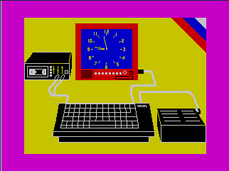
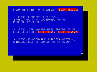
so common outside former Soviet Union countries. Sintez 2, contrary to ZX Spectrum, has no ULA chip, but it's built entirely on TTL logic chips. Single-voltage DRAM chips are powered from 5V, fed directly from regulated power supply. There is also no RF modulator inside, only RGB output to connect by e.g. SCART to a TV. As a gaming machine, Sintez has joystickports for typical joysticks and one Kempston one. Near 1991, Mezon plant (also in Chisinau), started to make small quantities of Sintez 3. They were based on proprietary chip and had possibility to bump RAM to 128kB. |
|

| Manufacturer | Signal |
|
| Origin | USSR / Moldova | |
| Year of unit | 1991 | |
| Year of introduction | 1991? | |
| End of production | 1993 | |
| CPU | Z80 | |
| Speed | 3.5MHz | |
| RAM | 48K | |
| ROM | 16kB | |
| Colors: | 8x2=16 | |
| Sound: | 1-bit (in video out signal) |
|
| OS: | BASIC (Spectrum-compatible) |
|
| Display modes: | Text: 32x24 Graphics: 256x192 |
|
|
|
||
|
|
||
| Media: | By default used with tape recorder | |
|
Power supply: |
||
|
8-pin РШ2Н-1-17 (RSh2N-1-17) female at the computer:
|
||
| I/O: | 2 * Joystick 1x Kempston joystick Tape I/O RGB Out System bus (no connector) |
|
| Possible upgrades: | Not known, but possible. | |
| Software accessibility: | Easy (Spectrum-like) |
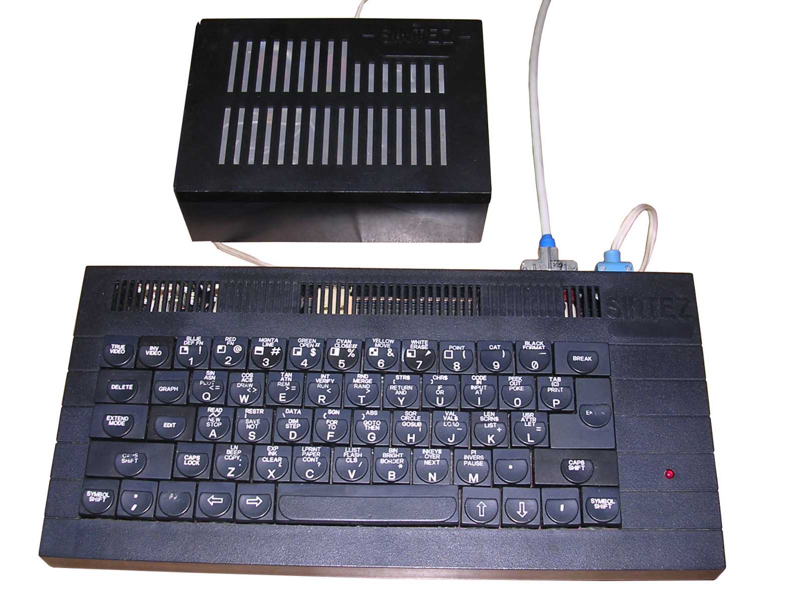

My unit is in relatively good condition. There is an original power supply unit and video cable with SCART connector. In its history someone needed this power supply unit for some other application and cut the connector, but preserved it inside power supply casing so it was only needed to solder it back. From the quality of production we can see that it was made in rather harsh economic conditions - there is no system bus connector, and Reset switch is installed on the rear, while in many units it was located on right side (needed longer wires).
| Contents: | Starting | Recording media | Pinouts | Links |
Starting:
It's a Spectrum-like computer. It starts right to BASIC.
If you perform checks, look for the following things:
- Fuse in power supply unit is 500mA. Power unit gives linearly-regulated
5V at 1A max.
- RGB connector needs RSh2N-1-29 (РШ2Н-1-29) plug. See photos.
- RGB and sync signals are tunable by trimmer resistors accessible from
side of computer. Tune for your TV set to see nice white background like
in Spectrum.
Recording media
See ZX Spectrum.
There are programs "TEST" and "REKLAMA" in tape sold with computer:

Pinouts:
WARNING: Some pinouts on an original, scanned schematics are
wrong. They may be related to mainboard, not connectors which are
installed by wires soldered to mainboard. In re-mastered schematic
pinouts seem to be correct.
RGB Video and connection for SCART plug (euroconnector), other pins have
some internal signals pulled out:
|
|
|||||||||||||||||||||||||||||||||||||||||||||||||||
|
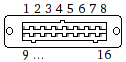
Joystick (I'm not sure about this pinout):
|
|
| 2 - Right 3 - Left 4 - Down 5 - Up 7 - Short to this 9 - Fire |

Kempston Joystick (I'm not sure about this one):
|
|
| 2 - Right 3 - Left 4 - Down 5 - Up 7 - Short to this (Vcc) 9 - Fire |
Tape:
|
|
| 1 - Out 2 - GND 3 - In |

Links:
http://trastero.speccy.org/cosas/JL/Sintez-M/sintez-m.html -
Sintez M in Spanish collection
http://www.retropages.hu/Gepek/Sintez/Irodalom/Sintez.html - In
Hungarian collection
http://speccy.info/Sintez -
Russian Wiki page.
http://museo8bits.com/wiki/index.php?title=Sintez_2 -
Description of computer in Spanish wiki. THEIR DESCRIPTION OF POWER
(9V) IS WRONG!