![]()
![]()
![]()
![]()
![]()
![]()
![]()
![]()
![]()


All my content and ptohos

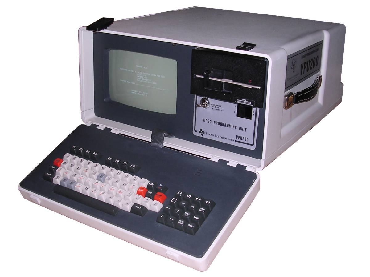
Texas Instruments VPU200
This device called "Video Programming Unit" or VPU is
an industrial computer from 1980s used to program PLC control units with
ladder logic programs. Then the program could be printed or stored in
the controller's memory to be executed. It has also a key lock, which,
by software, protects the memory from overwriting. The machine contains
everything needed: Floppy disk drive, keyboard, display and power
supply. Additionally, serial ports are available for expansion or
connecting a printer to print the program out. Inside, it is powered by
TI TMS9900 microprocessor known from TI99 microcomputer, but has 128kB
of system RAM as well as 128kB of additional RAM. Originally the floppy
drive used was a Kodak drive with very peculiar format allowing to put
2.7MB on a single 5.25" disk, but not all units had this drive.
Although it has been made in 1984, it has an older, but well tested
technology inside. Most of logic is made in TTL chips and only the most
complex things like clock generation, Serial I/O, disk control or ports
expansion is made on VLSI chips and they are a bit aged even for 1980s.
The display buffer is implemented on recirculating shift registers which
is a very Apple I-like technology and these parts were obsolete even in
1980s. However, using these registers allowed to have a reliable picture
board with almost no VLSI chips so it could be fixed using off-the-shelf
components available in the storage of industrial electronics workshop.
And that's how industrial computers have been built.
| Manufacturer | Texas Instruments |
|
| Origin | USA | |
| Year of unit | 1984 | |
| Year of introduction | ?1984? | |
| End of production | ?? | |
| CPU | Texas Instruments TMS9900 | |
| Speed | ?MHz | |
| RAM | 128kB (ROM OS) 128kB (System addiitonal RAM) |
|
| ROM | 8kB (simple diagnostics + loader) |
|
| Colors: | 2 | |
| Sound: | Beeper | |
| OS: | Monitor, ??? | |
| Display modes: | Text: 80x25? | |
|
|
||
|
|
||
| Media: | Built-in 5.25" FDD | |
|
Power supply: |
||
|
Built-in switching power supply |
||
| I/O: | Built-in keyboard 2 RS232 ports for connecting printer and ?PC? (?modem?) Expansion port? (5TI) CRU port ??? |
|
| Possible upgrades: | ?? | |
| Software accessibility: | Probably impossible |
I don't know much about my unit except that it was very
dirty, stored in poor conditions. I probably opened it first after
years, as I have not seen any traces of manipulation. Two boards are not
present, but they are missing in other units too so they are some
expansions.
A non-typical thing is a floppy drive used in my unit, it's Shugart
SA455-2 (documentation)
which is a normal 40-track drive, and usually these TIs had a specific
Kodak drive which could squeeze even 160 tracks with 17 sectors per
track. Although this format was extremely fragile, it was possible to
fit around 2.7-3MB on a single 5.25-inch disk.
| Contents: | Starting | Disassembly | Links |
Starting:
WARNING: This computer has about seventy (70) 4116 DRAM chips. These chips fail when there is no -5V power. So if in doubt, DO NOT start up right off the bat, but test the power supply first!
To test the power unit: Disconnect power supply
cable. Remember that some grounds are not connected in power supply but
are connected in backplane. Now what you need to check is three 12V
phases (mainboard, display and floppy phase, they are separated in the
hardware and never connected to each other), +5V phase distrivuted on a
few wires, -12V phase and the most important -5V phase. Be quick as the
power supply should not operate for too long without load and coils make
noises in such condition!
If all voltages are OK, try starting it up... with memory board
removed. My unit boots its firmware without memory board as it uses
128k on floppy disc controller board for it. If in such case there is
still -5V, turn the machine off and install board with 4116.
I cannot tell more about this unit as I don't have any disks and
software for it.
For your convenience, here is the pinout of power supply unit in the PSU. The connector to backplane is 1:1.
===============================
| 1 2 3 4 5 6 7 8 9 1 1 1 1 1 |
|___________________0_1_2_3_4_|
| 1 - +12V for floppy drive 2 - Power-on 3 - -5V 4, 5, 8 - GND (Logic) 6 - GND for floppy |
7 - GND for display 9, 10, 11 - +5V for logic and FDD 12 - +12V for logic 13 - +12V for display 14 - -12V for logic |
(display connector is similar, 9-pin, counted the same way 1, 9 - GND; 6 - +12V; 5,7,8 - signals; all other are NC).
So after pressing the power switch, it should beep a few times and
finally, after a short time, show a picture on screen. There will be a
menu for booting from disk, formatting disk, copying disk or running
diagnostics.
Disassembly
You need a long screwdriver which ends with a hexagonal
socket. It must be long enough to reach between the display unit from
the top, to remove screws from there. Another problem is that literally
no metric hexagonal sockets fit these screws, so I needed to modify a
6mm socket using a flat file to enlarge the socket a bit.
The general order is:
0. Main casing: Screws at the rear-bottom, screws in front.
1. Remember to clean the air filter on the side of boards cage! It is
usually dirty.
2. Remove two metal brackets locking boards, now boards can be removed
They are color-coded.
3. Remove 4 screws using the hex-socket screwdriver to remove display
unit.
4. Remove floppy drive (remove its side screws and shove to front).
5. Remove Floppy drive cage, also these hex screws on the bottom (power
supply unit becomes visible).
Because the bottom may be shielded, retain the rubber grommets which
should be under display unit.
Links
http://web.archive.org/web/20010710055831/http://www.sea.siemens.com/automat/product/plc/505/au505dl.html
- Some downloads for Simatic 505 and 560 PLC controllers.