![]()
![]()
![]()
![]()
![]()
![]()
![]()
![]()
![]()


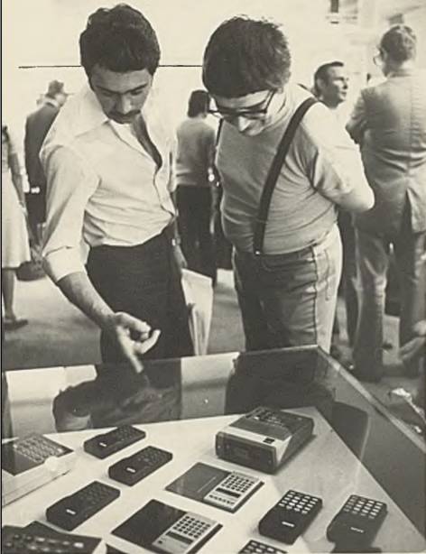
All my content and ptohos

ELWRO DESKTOP CALCULATORS LIST
MCbx 2011..2016
 |
SOURCES: Photos from internet auctions, inspecting lots of
units in flea markets. THIS LIST MAY NOT BE COMPLETE (and probably isn't). It probably is not 100% correct too. Because there were many calculators, some made using currently available parts, not ones designed in schematics, it may not be OK for all units. If you have an unit with different guts, it's normal. A WORD ABOUT POWER: Elwro calculators were manufactured in quite unstable market conditions, so many times only available components were used. This applies to power connector too, so you can find these 4 types of power: - Cable going from a hole near bottom edge of rear cover. Hole for socket covered by piece of plastic/laminate. - Cable going from a hole in a special plastic cover covering power socket hole in rear cover. - Typical 2-pin "Radio type" socket. - Typical 3-pin socket, as seen in computers (early 105LN). And all these calculators need 220-230V AC, 50Hz. |
WHAT IS NOT COVERED (only listed as existing models):
- Pocket calculators:
- 440 (Bolek with poor manufacturing process, early units not labelled
Bolek but "Elwro 440"),
- 441 Bolek (simple model),
- 442LC Jacek (The only Polish LCD!, black or silver metal housing),
- 480 Lolek (scientific model),
- 481 Lolek (scientific, better manufacturing process),
- 482. (???)
- Printing calculators:
- 230, (???Soviet Elka clone???)
- 240,
- 242,
- 255L,
- 255N, (2xx were printing models)
- 330,
- 343
- Eltra K-741, Unitra Brda series, etc. It's NOT Elwro.
- Magda - LCD pocket calculator made in small quantities on Japanese
parts, probably recovered from licensing material.
In general, the 3-digit type designation was used to inform about
calculator capabilities (source):
- Digit 1:
- 1 - Tabletop calculator
- 2 - Tabletop calculator with printer
- 3 - Tabletop calculator with printer and display
- 4 - Portable calculator
- Digit 2:
- 0 - basic 4-operations
- 1 - 4 operations with percent and K-constant
- 2 - As above with 10^8 overflow?
- 3 - As above, with 1/X, X and X^2.
- 4 - As above with one-number memory
- 5 - As 3 and two-number memory
- 8 - Engineering
- 9 - Programmable
- Digit 3: Version, usually it means that the same functionality has been
achieved with different components. Additional PCB revisions were marked
on PCB with letters like "Elwro 143A".
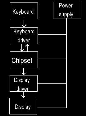
TYPICAL COMPONENTS or how the calculators are described: - Power supply unit - supplies all needed voltages to run both logic part as well as display, which in some cases requires special voltages. - Chipset - set of chips (or single chip) used to perform logical calculator functions. - Display - A device to show numbers. - Display driver - A device to transform results from chipset to display-compatible signals. - Keyboard - A set of keys to control the calculator. Usually aligned in multiplexed grid. - Keyboard driver - usually built-in chipset, circuit to transform pressed keys to commands for chipset. In Elwro desktop calculators, chipset may be single-chip or (usually in some scientific or financial calculators) composed of multiple chips, with keyboard driver built-in. Power supply unit is usually the same transformer-based one supplying two voltages: For logic and for VFD display tube which requires a bit higher voltage to operate. Also a AC filament for tube is supplied by mains transformer. Display driver may be realised on transistors, integrated circuits or hybrid circuits. |
 |
Quick jump:
Simple: 105L 105LN
EW-115 EW-116
120L 130
131 140
142 141 143
144 151
Scientific: 180 181
182 183
184 Programmable: 190
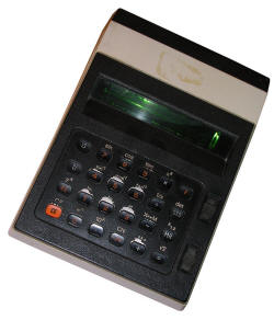
![]() ELWRO 105L
ELWRO 105L
The first calculator made by Elwro using Busicom's technology, maybe a
license (as in 1970s Poland bought many licenses from western
countries). Built around Japanese parts, Mostek MK6010 chip, with
transistor-resistor circuits to drive 12 Futaba VFD tubes. Remember
these circuits, in later models Elwro used hybrid circuits (Japanese
first, Polish and soviet later), later switching back to transistor-resistor
because lack of components (Telpod manufacturing hybrids was doing
something more important). Elwro 105L has an unusually long shape and
it's its first known Elwro calculator based on Japanese project. This
shape is taken from earlier Busicom model, which used logic chips,
not calculator-in-a-chip circuit. L here could mean "Licensed".
Power supply: Transformer-based
Chipset: Mostek M6010
Display driver: Transistor-based (see
photo here)
Display: 12 VFD Tubes, probably Futaba 1001 / DG1001
Keyboard: Spring buttons with sliding decimal place switch
Source:
http://gallery.olek.waw.pl/inne_zdjecia/stara_technika/ELWRO_105L.jpg.html
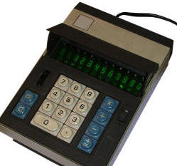
![]() ELWRO 105LN
ELWRO 105LN
This is a very popular unit, first really mass manufactured. Simplified
version of Busicom 120DN, used 12 Futaba VFDs too. In some units VFDs
are driven with hybrid circuits made in Poland (GC-003), some use "black
boxes" (JRC IC-3552).
I have no idea who exactly made these circuits, as they were probably
manufactured in Telpod workshops only. From former Telpod employees I
got two names of hybrid circuits designer centres: OBREM (for analytical
devices, no idea about acronym) and OBRMHiR (Ośrodek Badawczo-Rozwojowy
Mikroelektroniki Hybrydowej i Rezystorów - Development-research centre
of hybrid microelectronics and resistors -
their web page archived).
| It has a wheel rotary switch for setting decimal places mode. Switches
are purely mechanical. Elwro simplified this model very much to
manufacture is as cheaply as possible. PCB was used as in Japanese
models, but most connectors can be seen only in earliest models, in
later units they're gone - wires are just soldered to pads. Yes, edge
connector of keyboard too. In later models they drilled holes in PCB, so
it looked more professional, but in 105LN wires are just soldered to
edge connector pads and they stick from behind the board. Power supply: Transformer-based, "canned" one. Chipset: Mostek MK6010 Display driver: Hybrid chips, Japanese or Polish Display: 12 VFD tubes, Futaba DG10 Keyboard: Spring buttons with rotary decimal place switch Source: e.g. my units |
 |
![]() ELWRO EW-115
ELWRO EW-115
Used Soviet VFD tube, because import from western countries was very
difficult. It was Soviet IW-18, VFD tube designed for calculators: 8
digits and minus. It needed some construction changes, mostly re-wiring.
In the left, manufacturer's logo instead of rotary decimal
places switch. Probably in some units they used Soviet ICs.
Power supply: Transformer-based, "canned" one.
Chipset: ??
Display driver: ??
Display: ??
Keyboard: Like Elwro 105LN but without rotary switch
Source: Mentioned in
Mera bulletin from 1977, page 40
![]() ELWRO EW-116 (Elwro 116)
ELWRO EW-116 (Elwro 116)
Two major changes: One: it's made using better process, Second: some
units are not using IW-18 but 8 or 9 separate IW-6 VFD tubes. IW-6 tubes
are LIKE Futaba tubes... LIKE, doesn't mean the same. They're few
milimeters bigger horizontally. These tubes will be used in some later
models.
Power supply: Transformer-based
Chipset: ??
Display driver: ??
Display: 9 VFD tubes (one for sign)?
Keyboard: Like Elwro 105LN but without rotary switch
Source: Mentioned in
Mera bulletin from 1977, page 40,
collection item,
Another Mera bulletin with photos (page 35).
![]() ELWRO 120L
ELWRO 120L
Like Elwro 116. Probably contained some metal stand to make it more
comfortable, but it was not the primary difference. Some models used an
exotic MCX74204 circuit which was manufactured in very small quantities
by Polish CEMI, probably from pre-made stuctures (MCX is a designation of
raw structure) packed to ceramic DIP40 housing.
According to Mera bulletin, model 120 was made using only components
from Poland and Eastern Block countries.
Power supply: Transformer-based, "canned" one
Chipset: CEMI MCX74204 (source)
Display driver: ??
Display: ??
Keyboard: Like 105LN
Source:
Alek's site ,
Auction archive,
Mera bulletin with photos (page 35)
![]() ELWRO 130
ELWRO 130
Used a foreign VFD tubes and HD36290 chip popular in Canon pocket
calculators.
Power supply: Transformer-based
Chipset: HD36290
Display driver: Built-in chipset
Display: Futaba 9BT02 - small rectangular 9-place VFD tube.
Keyboard: ??
Source: Schematic in
Leon Instruments site (?article
saved but no schematic?).
|
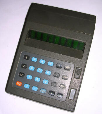
Better keyboard. Well, today it's not better, membrane keyboard has smaller and more comfortable keys but today distance foam falls apart between contacts. It's possible to clean this foam away, it will work but will make multiple clicks. And more functions: Simple memory, "finance mode" with 2 decimal places, 1/x, 00 and % keys. Using a 12-place tube with Memory/Error/Minus signs. which in current chipset are not used. Power supply: Transformer-based, PCB-soldered or fastened one Chipset: Soviet K145IK508, K145IK1802. Display driver: Soviet K161KN1A Display: Soviet 12-digit VFD tube IWL1-8/13 - 12 digits + -/M/E. Keyboard: Membrane, black-white-orange with rocker power switch and sliding decimal places switch. Source: e.g. my unit |
 |
![]() ELWRO 140
ELWRO 140
No "finance mode", but squares, square roots and finally full-featured
memory as seen in today's calculators, with M+, M-, X->M, MC, MR keys.
Because keyboard was too small some keys had to be "shifted". Display:
IW-18. Chip: MPS7545-004.
Power supply: Transformer-based, fastened to board
Chipset: MOS Technology MPS7545-004
Display driver: built-in chipset
Display: Futaba 9BT-02 - 9-place rectangular VFD tube,
smaller than window.
Keyboard: Membrane, black-gray, power switch is slider while in a
bottom there is a "1" quality sign
Source: e.g.
this movie ,
Schematic in
Leon Instruments site (?article
saved but no schematic?).
![]() ELWRO 141
ELWRO 141
See Elwro 140. The only difference is with displaying tubes: They're 9
?IW-6? Soviet VFD tubes.
Power supply: Transformer-based
Chipset: MOS/LSI MPS7545-004
Display driver: ?transistor-based?
Display: 9x VFD tubes
Keyboard: Membrane , blue-black or grey-black keys, sliding power
switch.
Source: Schematic in
Leon Instruments site (?article
saved but no schematic?).
This advertisement,
collection page
![]() ELWRO 142
ELWRO 142
From outside very similar to model 140. Exact differences not known.
Power supply: Transformer-based
Chipset: ??
Display driver: ??
Display: 9 VFD tubes
Keyboard: membrane, blue-black
Source:
This page
|
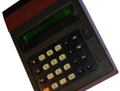
Built with Eastern components, CEMI circuit and Zatra transformer, number is displayed on 8 IW6 Soviet VFD tubes + 1 tube for minus and memory indicator. Known A and B models with slightly modified power supply. There's also 143K PCB revision, some photos show it with IW-18 tube, while other with 9 IW-6 tubes. Usually black case with blue keys. Rarely used 3-pin power connnector instead of typical in these machines 2-pin "radio" type. Power supply: Transformer-based, fastened to PCB Chipset: CEMI MC74007 Display driver: Transistor based Display: 9 VFD tubes, IW-6. Keyboard: Membrane, blue-black-orange keys, sliding power switch Source: e.g. my unit |
 |
![]() ELWRO 144
ELWRO 144
The most popular calculator manufactured since early 1980s till early
1990s. All experiences from developing earlier models resulted
in 144 model, which used IW18 tube, MC14007 and transistor-resistor
drivers. Only typical operations could be performed: +, -, *, /, %, sqrt, +/-, decimal point setting and memory operations.
This calculator had 3 models, but differences were small: track sizes
and power supply simplification (PCB-mounted mains transformer). Units
from 1990s are very poor quality, made of paper-based laminate and too
small quantities of soldering alloy.
| Power supply: Transformer-based, soldered
to PCB (fastened in early units) Chipset: CEMI MC14007 (formerly MC74007 according to datasheet) Display driver: transistors Display: IW-18 VFD tube Keyboard: membrane, white-black-orange, black-red, blue-black-orange, different variations of power switches (mostly sliders), white and brown cases, sometimes with model printed on the top. Source: e.g. my units,
|
 |
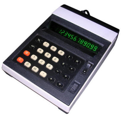
![]() ELWRO 151
ELWRO 151
The last upgrade of Elwro's simple calculators. Casing is as in 144, but
keyboard has been revamped, keys are longer in width, like in 183
series. 12-digits and minus in one VFD tube, capabilities similar to
144 but probably two-number memory.
Power supply: Transformer-based
Chipset: ??
Display driver: ??
Display: 12-digit VFD tube with minus sign / M / E.
Probably like in Elwro 131.
Keyboard: Membrane, black-white-orange, longer keys, two
sliding switches (?memory?)
Source:
Legendy PRL site,
|
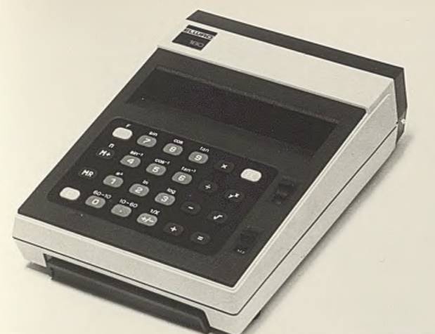
Scientific calculator with enhanced functions, 12-digit VFD and DEG/RAD support (by mechanical switch). All features of 144 plus: Pi, sin, cos, tan and their inversions, e^x, ln, log, degree to radian and back, y^x. Power supply: Transformer-based Chipset: ?? Display driver: ?? Display: 12-digit VFD tube. Keyboard: membrane, black-blue-orange with sliding switches Source: collection page, this movie, photo |
|
|
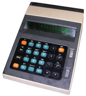
Small keyboard layout change. Still built with western components, as there were no components for these scientific calculators in eastern block countries. Built around uPD953C chip and single 9-digit VFD with 8 active digits (one for minus and memory). Power supply: Transformer-based, fastened to PCB Chipset: Nec uPD953C Display driver: Built-in chipset Display: 9-digit rectangular VFD, smaller than calculator's window. Keyboard: Membrane, black-blue-orange, sliding switches. Source: e.g. my unit,
|
 |
|
Making 181 with Eastern components? Let's use old good IW-18 to display, but K145IK1301 soviet chip. Some functions were added, support for bracketed computation, simple DET function - delta of polynomial, coefficients are "("-separated?. And different memory handling - using STO/X->M/MR/M+/CM keys only. Soviet chipset required external clock generator, here implemented on K165GF3 chip. Power supply: Transformer-based, fastened to PCB Chipset: K145IK1301, K165GF3 as clock generator Display driver: transistor-based Display: IW-18 VFD tube Keyboard: membrane, black-orange keys. Power switch and function sliders. Functions painted on and above keys. Source: e.g. my unit, collection page |
 |
![]() ELWRO 183
ELWRO 183
Used different casing, the same as MIK-1 CA80 teaching computer.
Manufactured in small quantities in late 80s/early 90s.
Power supply: Transformer-based
Chipset: ??
Display driver: ??
Display: 12-digit rectangular VFD tube,
Keyboard: Membrane, long keys in new casing,
white-red-orange.
Source:
Retroplayer site,
Photos on Leon Instruments site (mirror)
![]() ELWRO 184
ELWRO 184
Changes not known. Existed.
Power supply: Transformer-based
Chipset: K145NK1301 (source)
Display driver: ??
Display: ??
Keyboard: As in Elwro 183
Source:
Archive auction,
another one,
small
photo,
![]() ELWRO 190
ELWRO 190
Programmable calculator built in very small quantities in late 1990, but
design was much, much older. Made of Polish chips (chips made to order
too) only. Today it's very rare. Programmable using 10-variables programming
chip with jumps and IF instructions.
Power supply: Transformer-based
Chipset: CEMI MC14009, MC14010, MC14011
Display driver: ??
Display: 12-digit VFD
Keyboard: Membrane with long keys, white-red-orange-black
(instruction keys are black).
Source:
Legendy PRL Page,
Leon Instruments reconstruction (mirror),