![]()
![]()
![]()
![]()
![]()
![]()
![]()
![]()
![]()


All my content and ptohos

Commodore 16 - 64kB memory upgrade
This howto shows exactly step by step how to perform modification described here. Thanks to Raf, who motivated me to perform this mod on my C16.
Open C16: Remove 3 screws at the bottom. Remove keyboard lid, disconnect ribbon and LED cable. In my C16 white cable was going to the left in keyboard and red cable to the left in LED plug.
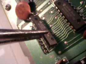
Carefully slip the clip out the expansion port shield. Now you can open the RF shield of mobo. Locate U5 and U6, they're ..416 Dynamic RAM chips.
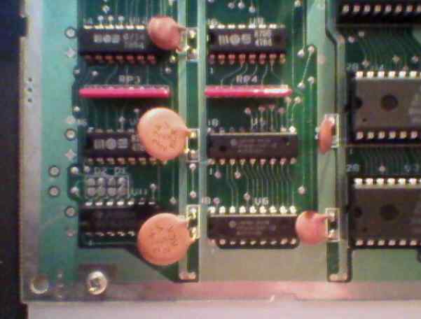
The photo shows lower left edge of the mainboard. U5 and U6 are two not MOS manufactured chips in the second column. U8 - above U5 (and RP4), U7 - to the left of U5 covered by decoupling capacitor.
REMOVING U5 AND U6.
If you have a complete soldering equipment, you can desolder them. But I had only a soldering iron. The technique I use is a simple destructive chip removing I don't recommend, but it may be done if nothing else can be. It's cheap because it doesn't require any specialized tools but destroys removed chip. All things you need is a sharp knife, soldering iron, a sewing needle and pliers. Best pliers are medical ones, with handles like in scissors. They can be also locked to hold something constantly. Begin with cutting all pins on one side. Cut them near the point where they bend, on chip side. You can use other pins as support point for a lever-like cutting but be careful not to cut delicate tracks below!
Now gently bend the chip upwards. Take it with pliers and bend it many times to break pins, gently pulling the chip each bend (do not pull it of the board!). If you won't pull it, you'll leave very short pins in the board.
You'll end with something like this:
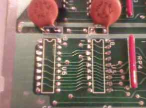
Now the thing is simple: For every pin do: 1. Heat the solder, 2. Pull the pin out from board using pliers. Maybe it sounds simple but you need 2 things to know:
1. Don't use too much force - we don't want to pull off hole metalization which contacts both sides of board. In fact after heating it should come off easily except a few pins bent on bottom side. Soldering tip should have some solder on it, it'll make melting faster.
2. Watch where you put these pins! And never leave them in/near mainboard or in the computer case. It's very easy to make a short circuit in m/b with them.
OK, we haven't removed the mainboard from the bottom part of case till now so we had a comfortable places to put arms while working with mobo. Now, remove the mainboard by removing screws. There will be 2 screws near metal side shield. Remove the one closer to the arrow on the lower part and, as I remember, closer to the shield on the upper. Anyways, the shield screws WILL be a bit different. Now we can remove mainboard.
OK, but we want to solder sockets there. So we need a clear holes. You can use solder sucker... if you have one. I don't have so I had to figure some "McGyver's method" out.
Get a sewing needle. They're made of high-carbonated iron and diffused by thin layer of nickel. If you rub it in fingers, there's no way to solder to it. It just won't stick.
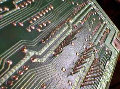
So put the mainboard on a table the way that U5 and U6 place is outside table, over the floor. Take the needle in pliers, rub it in fingers. Then heat up the hole, stick a needle in there thru the board, take soldering iron off and remove the needle. Repeat it with all holes avoiding manipulating the bottom side of PCB. If you feel that needle gets in/out too hard, just let it cool and rub it in fingers one more time.
As you turn the board, you'll see "craters" of solder on the other side. We need to remove them by simply cutting them off with a knife. Remember to rotate the board, so that pieces of solder won't short other pins.
Now check with ohmmeter haven't you cut any lines. If you did, repair it with wires or solder. We're ready to solder sockets there. If socket's pin can't go into hole, repeat the needle procedure.
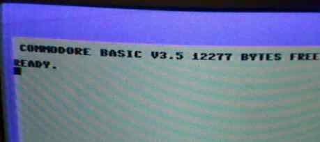
Now put two 464 (4464, 41464, 2464 etc.) into these sockets. Check everything one more time. Any short circuits? Finally power up the computer. You should get a normal startup message with 12277 bytes free.
OK, if it booted that's good. We can proceed to preparing two additional addres lines to get 64K.
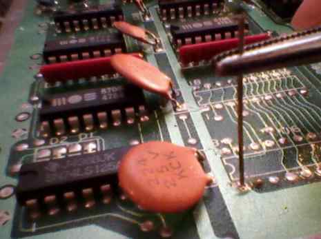
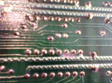
The first thing is to cut 5V blocking our address lines in multiplexers. They're pin 14 on U8 and pin 2 on U7. U8 is quite simple - just flip the board to solder side and you'll see 5V rail. Cut it as in picture (5V goes also to pin 16 and it must stay there to power the chip):
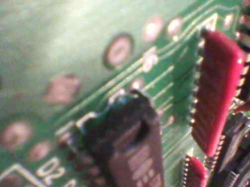
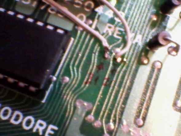
U7 is more complicated. 5V line goes on the component side from its pin 16, which must stay powered. So we flip the board back to the component side and look in pins 1 and 16 of U7. Unfortunately it's covered by the chip and this is the best photo I could do. The thing is to stick a knife just below pin 16 and try to cut this track coming down from pin 16. After some cutting check with ohmmeter is there a conductivity btween pin 16 and 2. If not - very good!,
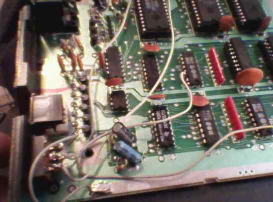
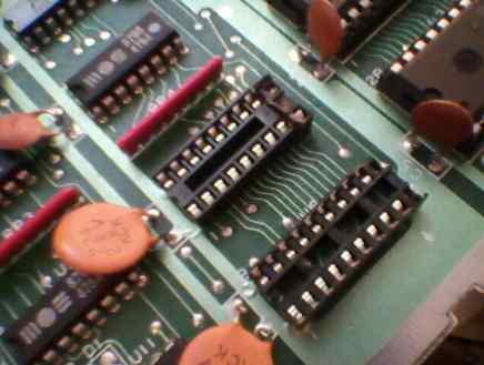
Now let's solder wires to these pins: to pin 14 of U8 and pin 2 of U7. If you want to make your C16 always 64K, solder them to U2 pin 22 (U8/14) and 21 (U7/2). If you want to switch between 16 and 64K, get a switch with 6 pins like this:
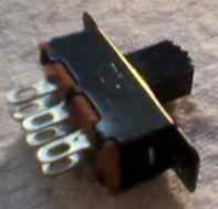
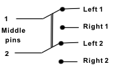
and install it somewhere in your C16. Solder U7/U8 wires to middle pair. This pair is switched between left and right pair. Connect one (left or right) pair together and solder it with a wire to ground or 5V - you'll find ground in silver areas of mainboard. This will be 16K. Now solder the other pair to pins 22 and 21 od U2, so that when it connects it'll connect pin U2/21->switch->U7/2 and U2/22->switch->U8/14.
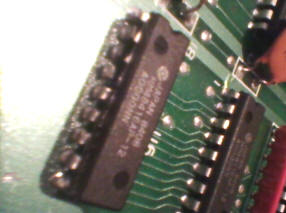
And how to avoid soldering to socketed IC U2: Take it from here (the IC on the left is U2, pin 20 on the right). I don't know about other revisions, so better check it with ohmmeter:
Check again everything with ohmmeter. Switch your C16 in 16K mode, start it. Should show 12K free.
Switch off, change mode, wait 5 seconds to discharge capacitors, turn it on. Should show:
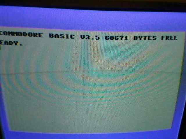
Plug everything in (keyboard, LED, lid) and test.
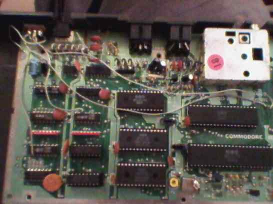
Finally 2 photos of my installation: