DIY book scanner
DIY book scanner. English translation of notes made post-build.
There were no building plans.
2015 MCbx
   __/\_/\__
  /_(*_l_*)_/\  ASCII art test. If you see the cat in a box, you will likely see text drawings
 //______W_/\/  in this document correctly.
  |         ||
  |_________|/MCbx
|
INTRODUCTION Scanner is a device to digitize printed material into computer-readable form.
Digitizing data allows quick building of searchable databases, data mining or
easy and fast research. Scanning books allows to quickly search, recall and
share information, especially if someone has many, many books on the shelf. Many companies try to show book digitizing as theft - it isn't. I have books which were published in 100 or 500 copies. Ask any publisher for such book you e.g. lost in flood and you'll see how worth are all licenses to them.
But digitizing books takes time. Imagine you have 300-page book, which you scan with flatbed scanner, 60 seconds per sheet (2 pages, scanning, turning page, positioning, pressing button). 150 minutes if you're really quick and have no breaks or distractions. But usually scanners aren't so fast. Before e-book markets, e-book making was an important part of computer Scene. Polish groups
(e.g. SCAN_DAL or UUK) used home scanners to transform books into high-quality OCRed ebooks, literally remaking the book, like typesetters and metrampagers
did before printing. In early 2000s it took them even few weeks to "rip" a book completely.
In this text I present a quick-and-dirty version of a DIY book scanner based on a different principle. This scanner uses 2 cameras to take photos of 2 pages of a book simultaneously. It takes about 3-4 seconds if cameras need to focus. Next, platten is lifted, page turned, platten goes down (3 seconds), which takes
ca. 7 seconds per 2 pages. In result, 17-18 minutes per 300-page book. If you have good cameras with constant focus, you can minimize picture taking time. If you get used to operation and "feel" the device, you can turn the page under 2 seconds. Camera-based scanners are very fast.
This documentation is based on ASCII file and contains ASCII drawings. The file has been made in my trusted HP 200LX palmtop after building parts of a scanner - it was not a plan, it was a log. There was no plan at all except "build something usable". Later, photos of a ready device have been taken to complete description and everything is now ported to HTML.
I don't know much how to make things of wood, I have only basic tools (except screw cutter, this is the most complicated
tool) and I usually don't use calliper as much as I want. Everything except cameras comes from recycling or disassembly of old parts (mostly furniture). But it is still possible to make operable scanner with such resources. |
 |
Here is one of scanned pages after processing with ScanTailor and thresholding
to monochrome. Because of image size, it is resized from ca. 4900pix to 2048 pix
in height, keeping ratio.

DIMENSIONS (usually unneeded, as you will likely have different pieces of wood):
Single plate (base) board: 50x50cm
Vertically worplace is ca. 30cm because: a. platten, b. stator mounting, c. Cameras range.
Base board: 45x110cm. Stator goes a bit to the front.
Cameras heights have been discovered experimentally. Start with lower positions and go upwards until you get more or less straight view.
As sources of components, Author used remains of wardrobe, bookshelf and some steel junk (C-shaped bars). All components except cameras have been taken from recycling junk. Complete building time:
Two weekends.
It is very important to keep plates angle exactly 45 degrees. In the document I will call
sliding piece of plates also "Stator" contrary to constantly moving glass "platten".
Every hole for screw has to be cut to fit screw's head in the surface. OK, maybe except topmost stator mounting, in which screw goes 45 degrees to board.
DO NOT use rubber pads under base board or you will have to wait for cameras to stop shaking. |

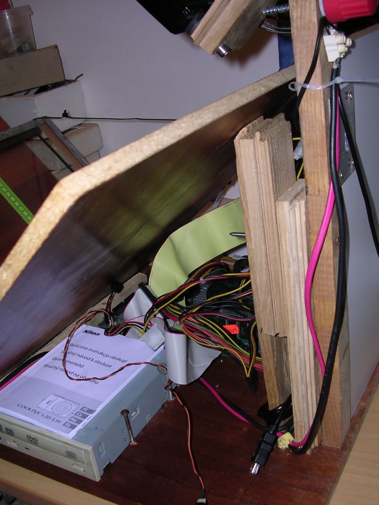
Scanner under construction |
Camera used: Any 10MPix or better. Should support taking photo using PTP (gPhoto2) by USB cable. Or CHDK, Canon cameras were too expensive for this project. My unit is made around Nikon Coolpix L20 cameras. In fact, very good cameras have German or Japanese lenses.
CONTENTS
1. Stator right-hand side construction
2. Stator left-hand side construction
3. Stator shifting mechanism
4. Camera column
5. Crank mechanism
6. Mounting camera to column
7. Platten
8. Right-hand camera column
9. Loghting
10. Electric part
11. Shutter
12. Meters
13. Computer
14. Appendices and scripts
STATOR RIGHT-HAND SIDE CONSTRUCTION:
               /
              /|   <---Cut 1
             / |
            /v |
=================
v - wooden part cut (in diameter) like this:
   __
  /  |
 |___|
Cut 1 and its mounting:
   /|                /
  / |               /
  | |              T/|
  | |             // |
 ......          //  |
  |_|           / |  |
========          |  |
Screw's head (T) limits available vertical space to ca. 43cm. A whole platten goes below it.
Side view:
 __________
|          |
|    ||    | <--Cut 1 is in the center of stator part
|    ||    |
|    ||    |
|vvvv||vvvv|
============
Both vertical and horizontal parts should be fastened from underside to the base plate. Horizontal part in 3 points, vertical part in 2 points to prevent rotating. Horizontal part should be mounted to stator plate between screws connecting it from base. All holes should be cut to fit screw's heads - the plate must be smooth in its bottom!
LEFT-HAND PART OF STATOR (SLIDING PART):
   \
   |\
   | \
   |_v\
==============
Use sliding part only if you plan to scan VERY thick books, like magazine yearly archives. If you want to scan typical 40-400page books, it's not needed and malicious sometimes.
Use the same cutting and "V" part. It is important not to screw this part to base, but use additional flat piece of wood to make triangle (see "_" in drawing above). Part should slide using this part. Here is a detailed view:
Up to Cut 1               \\
|  |                       \\
|  |                      __\\
|  |---------------------|  \\\
|__|_____________________|__| \\ <--"Stator" plate
Fix horizontal base to vertical part using two screws coming from the left, then one screw from the right through "V" part, then fix plate to V-part and Cut 1.
LEFT-HAND STATOR SHIFTING MECHANISM
Fix (preferably from bottom) two flat parts with spacing exact as width of base of the triangle. It should slide like in a slipstick. Allow ca. 15cm of plate-plate drawback. Seen from top through plates:
 _________________________
|      |       v||v       |
|      |       v||v       |
|      | ===   v||v       |
|      |X======v||v     X |
|      | ===   v||v       |
|      |       v||v       |
|______|_______v||v_______|  <--Still part
     Moving part
Where "=" are vertical flat parts. "===" are fixed to base making track for "======".
To shift the part before scanning, a screwed rod and crank is used in conjunction with camera column. For most books V-like is enough, for some very thick ones, like magazine yearly archives, it is needed to apply some drawback to make platten go into book smoothly.
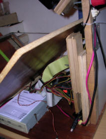
In both photos there is sliding mechanism, camera column and unfinished
crank mechanism. It is needed to use rod which doesn't deform on its
sides when squeezed in its width. It is not needed to cover the
"slipstick" from the top, as it slides smoothly and doesn't go upwards
(in fact I had to stick a few layers of tape below to make it go a bit
upwards to correspond with right side stator part). |

 |
CAMERA COLUMN (LEFT)
In my first model, only left-hand camera was used. I had opportunity for second camera and added right-hand camera to shoot two photos at once.
In the left, the vertical camera beam is mounted perpendicularly to base. It is needed to mark the geometrical center of stator (in depth), and center of beam, then mark center line on base and move the beam on this line to proper distance. Then holes can be drilled and 2 screws fastened from bottom of base. This will make the column exactly in the center of plate.
To prevent vibration and keep everything firmly in place, you should add another piece of wood to keep column from wiggling back and forth. See the picture:
  |
  |
  |
  |  \      /
  |  |\    /|
 /|  | \  / |
/ |  |==\/  |
==============
This piece of wood is cut special way (45 degree) and fastened to base and column, two screws each side:
      ||
    /|||
   / |||  <---Fasten
  / / ||
 / /  ||
/_/   ||
==============
Above this piece of wood, drill a hole with a long drill, then drill a corresponding hole in vertical part of sliding piece of plate.
Now cut a screw on a long steel rod. Bend the rod with crank on side without screw. Using this crank you will be able to quickly and precisely shift plate without problems.
CRANK MECHANISM
It looks like this:
       ||             ||        \\
  |ZZZZ||PN===========X|=PN      \\  <--Sliding part of stator
  |    ||             ||          \\
--|  /J||             ||           \\
    // ||             ||            \\
   //  ||             ||             \\
  //   ||             ||=============V\\
=======================================
From the left:
- Crank, part is in pipe "ZZZZ". Pipe may be even twice wide as crank rod, then it's needed to use two nuts to hold rod in its center, nuts with a bit larger inside diameter than a rod.
- The screw on the rod starts from "PN" - P is a washer, N is a nut applied with force to the end of screw, to make crank spin freely but not go back and forth (in the picture right-left). This nut should not unscrew during normal work.
- === is a screw on the rod. Rod is ended with "PN" - Washer and nut.To make nut not unscrew use hydraulic teflon-like tape.
- "X" is a specially embedded nut:First, find the largest nut with hole corresponding to screw on the rod. If you see it from its front, it looks like (hole omitted):
  _.....
 / \    |<-- a - nut's height
 \_/....
Now drill part of hole in slider with a drill of diameter a. It should look like: |
 |
  |_   |
|   |__|
a    __
|  _|  |
  |    |
  |-|
   b
b is a thickness of your nut.
Using a screw cramp press the nut into hole. It should make its way in wood and not rotate. Usually securing with small nails is not needed, but if it rotates, apply them. Temporarily protect the nut using bolt, and cover it with washer with larger outside diameter. Drill 3 holes in its edges and lock it with 3 small screws. Looking into horizontal slider part it should look like this:
|           |
|    _W_    |
|   /   \   |
|   | O |   |
|  W\___/W  |
|           |
W - screws. We can see O - hole in the washer, nut is pressed under the washer. Screws secure the washer in place.
Remove securing bolt and screw rod into. Now by rotating crank, you can precisely slide the moving part of plate.
CAMERA MOUNTING
It is usually needed to do it few times to get proper camera height. Then after getting proper height fasten bolts. It should look like this:
  ||
  |||_  <--A hinge, the angle of its opening is different than in this picture
  || \\
  ||  \\/ <-Bolt for camera
I=||===\\
  ||         I===== - Screw to precisely set angle.
The base is a small wooden block, about 5x20cm, the hinge is fastened to its shorter side. In the end of this block a hole for camera bolt is drilled and camera bolt is screwed. A rubber washer (like in a water tap valve) is applied to secure the camera and mount it in proper rotation.
The other arm of hinge is mounted with at least two bolts to holes in column. To make it movable don't use screws, but nuts and bolts.
It is important to maintain the proper horizontal angle of the board not to tilt the camera.
To properly tune the camera, mount it and watch is the bottom of its picture parallel to the spacing between plates.
After proper setting of camera, it's needed to drill additional hole for a big and long screw ("I=====" in the picture) - it will be used to keep the angle of camera and eventually correct it. |

 |
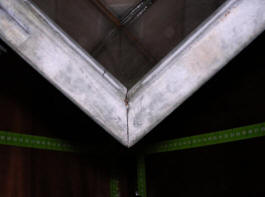
PLATTEN
This part is used to keep pages opened at 90 degrees. My platten is made of glass from a bookshelf. Platten should be a bit longer than stator plate. It is made of two glass sheets aligned in "V" letter.
We have our glass sheet:
 ____
|    |
|    |
|    | <-B
|____|
  A
We need C-shaped bar of length a bit smaller than 4*A+2*B. C-shaped bar looks in diameter like this:
  __
 |       | \
 |__     | / spacing between arms
In spacing between arms, you have to fit:
- Window foam pad
- Glass
- Second foam pad
- A bit of wood to join C-shaped bars
And it shoulg fit tightly.
First, cut a bar to two halves of length a bit smaller than 2*A+B. Each of these halves should be processed the following way:
In the middle, there must be a cut to bend the bar at 90 degrees preserving channel.
Simplifying, the bent bar looks like:
 \    /
  \  /
   \/
We need to cut a rectangular part in one side of channel, and triangle in the "Comb" of channel. Then it's only needed to bend the bar. The bar becomes much less durable in its place!
So here are the steps:
Step 1: Cutting rectangle in arm:
_____....____
_____|__|____
| One arm seen in front. Dots are edge of the arm in far. Comb in the bottom.
Step 2 2: Cutting "V" in the "Comb":
_____  ____
_____\/____
In the top you can see the cut from Step 1.
Now try it to glasses laying on stator plates (check 90-degree angle using set square!). Mark ends of glass sheets on the bar, cut arms in this height preserving comb. One side in, second out, bend 90 degrees to wrap edges of glasses.
So 2 glass sheets seen from the top with single metal bar looks like this:
   _______
  |   |   |
  |   |   |
 ||   |   ||
 ||   |   ||
 ||===|===||
Lines "||" and "=" mean a C-shaped bar wrapping glass sheets.
The second bar is placed on the other side.To fix the glass to bar, use the following "sandwich"
======
|DDDDDDD <-A wooden strip (e.g. from floor panel)
|XXX     <-Window foam pad
|ZZZZZZZZZZZZZZZZ <-GLASS SHEET
|XXX     <-Window foam pad
======
To make a full frame, join two bars using joints:
======
|DDDDD <- A wooden block protected with insulation tape
|DDDDD
|ZZZZZZZZZZZZZZZZ <-GLASS SHEET
|XXX     <-Window foam pad
======
The wooden block goes to both C-shaped bars. Drill the bar in its place and fix using screws.The platten should be squeezed to keep 90-degree angle using wide cable ties. In the angle sharp glass edge can easily cut the ties, so use piece of aluminium (e.g. from cans) to protect it.
To these large ties, fix the U-shaped metal bar to easily lift the platten to turn pages.
View from front:
  _____________ <--Cable tie goes around
 \\          //
  \\        //
  O----------O  <--U-shaped handle kept with cable tie
    \\    //
     \\  //
      \\//
       \/ <--Cable tie goes tot he edge of glass, protect it!
Such platten is quite durable and allows to be used without lifting mechanism - just lean it its the back to lift it.
Remember to glue foam pads on stator, the way that they won't collide
with a book. They prevent platten glass from scratching.
|


 |
CAMERA COLUMN (Right one)
I found that there is no space for support beam. I used a piece of wood (XX) to fasten it to stator support beam:
         ||
     //  ||
    //|XX||
   // |XX||
  //  |XX||
 //   |  ||
===========
LIGHTING
Scanner viewed from front with lighting:
      X    X
     /      \
    /        \
   |          |
   |>        <|
   |          |
   |  \      /|
   |   \    / |
_/-|---|\  /| |
   |   |_\/ | |
 ================
| Using normal 40W light bulbs (X), fastened on metal pipes bent about 45 degrees, mounted in hole drilled in the top of camera columns. Cable goes through pipe, hole in column and hole in a side of column:
  Pipe
---   ---
| |   | |
|_|   | |
 _____| | <-Hole for cable
|       |
|       |

From top:
 _____
|  :  | <- Hole for cable (unseen, drilled in wood)
|  O  | <-Pipe nest
|_____|
|
 |
Before fixing light bulbs, try their alignment. See the view from cameras, light bulbs should not be visible in glass. White ceiling few centimeters above bulbs spreads light nicely.
ELECTRIC PART
| OK, High-voltage is running here. Do not connect cables by twisting them, use insulation tape, cover critical parts, don't let any wire to be exposed and it'll be fine. If you have a power cable with plug, the safest way to service the electrical installation is to
keep the plug in your pocket. 3 wall surface switches are used. 2 are single, they turn light bulbs on and off, one is double. It turns on the power supply for cameras and a socket for computer.
Power supply unit consists of few parts. Transformer (TRAFO) gives 7-8V
at 1,5-2A. It is rectified in Gretz bridge (G) and smoothed with
electorlytic capacitor (>1000uF per camera). This voltage is linearily
regulated using LM317 tunable regulator to the voltage required by
cameras. There are two regulators for two cameras (useful if there are 2
different ones).
It is VERY important to connect grounding wire to sockets. Switching power
supply units don't like sockets without earthing. |
 |
230V--+---[SW]---Light 1
      |
      +---[SW]---Light 2           ----Monitor
      |                           /
      |   |SW|---------------[Socket]------Computer
      +---|  |
          |SW|---------------[TRAFO+G]----- Regulator ----<>-----Camera 1
                                  \
                                   ---- Regulator -------<>------Camera 2
                                                     Connectr
Regulator (Trimmer's slider is connected to its edge connector):
   3 _______ 2
+>--| LM317 |--+-------+---->Out       ___
    |_______|  |       |              | O |
        |1    |-|      |+             |---|
        |     |_|240R ===             |___|
        +--+---|      --- 470uF/16V    |||
        |  |           |-              123
       |-|/            |
       |/| 5K         ===
      /|_|
        |
       ===
Fasten separte or insulated heatsinks to LM317 circuits. For two cameras it's needed to have 2 regulators because:
1. Current from one regulator is only 1,5A
2. 2 different cameras may require 2 different voltages.In many cases it is
needed to add a small fan to cool linear regulators, in my unit it's
running from linearily-regulrate 5V supplied from transformer. It's a
small-power 12V fan, under 5V it runs quietly but efficiently.
Remember, the power disspiated by the linear regulator is ca.: P =
(Uin-Uout)*I Where: Uin - input voltage, Uout - output voltage, I -
current drawn. |
 |
SHUTTER
It's easy with CHDK, if you have Canon camera or with high-end cameras with
external shutter. I don't recommend ripping cameras to get their shutter
switches, as you may find button with 12 tracks going to it, which need
to be crossed in a special (and unknown) way to focus and take a photo. If
there is no way to trigger camera using external switch, it's needed to use PTP and Linux shell scripts with GPhoto2 program.
Generally, you need a switch which presses Return (Enter). There are 2 ways to do it:1. Get wires which connect Return key from your keyboard. It requires to dismount keyboard and use e.g. small socket for it. In my small PoS keyboard there was a space for small Jack socket. And it is needed to figure out which pins of IC are shorted when Return is pressed. "Shorted" means even 130 Ohms between them, because foil has its resistance. For protecting chip ports, if you have measured some significant resistance, add some to your connector.
2. Use PCB from old keyboard, connect proper wires and connect this keyboard as second one (two USB or one USB and one PS/2 keyboards may be used the same time).
The button is mounted in a small piece of plastic to platten's handle. Wires are going along platten's edges to its back. Presing button links proper keys and it results in pressing Return. For solution 2 it looks like:
Button      Connectr ____PCB
 \--------------<>--|____|------------[PS2-USB converter]---USB in computer.
Thanks to connector, we can remove platten for cleaning.
I've used second solution first (see photo 2 on the right), then
switched to first solution as more elegant and less demanding from PC. |


 |
SCALES
It is useful to add some measuring scales to plates. It allows to monitor book position during scanning and measure resolution easily.
Measuring scales can be made of freely available paper mesauring tapes from building/hobby shops. They can be fixed using a wide transparent tape. It is handy to add the following measuring tapes:
1. Resolution-marking - with marked inches (1in=2.54cm) to measure pixels per inch. Vertical scale goes in the center of plates, with zero in the bottom, horizontal one goes from user outwards, few centimeters above the bottom. This scale is also used to check won't book moved too much during scanning.
2. Additional scales showing maximum range
3. Plate drawback scale.
 ___________   ___________
|           | |           |
|    ---I---| |---I---    |
|   |   I   | |   I   |   |
|  =====I===| |===I=====  |
|   |   I   | |   I   |   |
|    ---I---| |---I---    |
|___________|~|___________|
Where: ==== - vertical inch scale, I - horizontal inch scale, --- and | - range scales, ~ - drawback scale (below stator).
"Horizontal" and "vertical" are relatively to picture shown in camera's screen.
In my 10MPix camera, I'm getting ca. 400dpi picture.
It's better to place a white paper (or other sheet) on platten not to confuse
ScanTailor later, but I haven't done it yet.
COMPUTER
Any small PC with USB ports (better USB 2.0) and Linux OS with gPhoto2 program.
It's good to have network adapter too, to send developed files by
network. I've started with a small embedded system with Cyrix Kahlua (like National Semiconductor GX1) 300MHz (like Pentium MMX 266MHz) and 64MB of RAM, but if you have 256MB or more you can afford
a simple GUI. If you have more than 2 cores and 1GB of RAM, you can even process with ScanTailor in PC
(but it's rather slow). Currently I'm using an embedded Celeron 1.5GHz and 512MB of RAM
to run Debian with software.In general, scripts for losslessly rotating 10MPix JPEG files (not to be confused with EXIF rotating
which is changing few bytes in JPEG contrary to matrix transpositions and
lossless recompression) are very slow on 64MB of RAM. Linux is a system with memory management different than Windows, DOS or some older Unix systems. If there is a memory unused, Linux will use it to speed things up, storing frequently accessed data in special buffers. If some program wants to use more memory, buffers are just freed
- memory is used, but system runs slowly. So if you add more memory, you'll in most cases just get faster system. 10MPix photo requires 30-40MB of memory to be processed,
if it's processed optimal way, and in Open Source tools it may not be. When 64MB of RAM are
installed, most of it (ca. 50MB) is used by system services (Display, console, network) and processing program, so not much is left for photo. Buffers, in such situation, do not exist. That's why the system must use disk-based space (swap) which is much slower. Generally prefer
>=128MB computers, because 64MB is really slow.
To operate scanner, special scripts are needed. I've made Bash
scripts to use both in general-purpose machine or in specialized
embedded PC configured for scanning only.
Here you can download shell scripts in two variations:
1. "On-demand" - an universal script for taking photos, acquiring images and separate script for joining from two cameras. It can be used in higher resource systems used not only for scanning.
2. "Environment" - is a complete environment written in Bash and Dialog to take photos, acquire, join and send to USB drive or FTP server. This software can be used in embedded systems. |
 |
Before installing these scripts, get the following packages (Debian Jessie):
aptitude install dialog mc fbi libjpeg-turbo-progs gphoto2 beep imagemagick sudo htop rsync ncftp
In Debian Wheezy:
aptitude install dialog mc fbi libjpeg-progs gphoto2 beep imagemagick sudo htop rsync ncftp
You can also install usbmount (USB drive
automounter) if it won't collide with PTP.
WARNING: In Debian Jessie there may be a problem with gPhoto2. The symptoms are following: Single photo is taken (or two, each from one camera), the second photo hangs camera (or both), request times out and gPhoto2 cannot shoot next pictures. I've found that the only way to fix it is to go to Debian Wheezy.
If you use GUI, make sure to permanently disable PTP camera automounting/detection or you won't be able to access them from gPhoto2. In LXDE, you usually have to forcefully remove gvfs packages, or it won't work, as options in PCManFM are not working for cameras (Tested under Wheezy).
Remember to look (gphoto2 --list-ports) how Your cameras are identified and change CAM1= and CAM2= lines from usb:001,... to your own - there may be e.g. usb:004 in your mainboard, it depends on USB bridge construction.
 On-demand scripts package
Contains operate.sh - script to operate cameras, join.sh - script to join two
directories and rotate images. Also contains Windows batch to rotate images, it
requires JPEGTran (http://jpegclub.org/jpegtran/).
Software used to process scans in high-resource computer:
- ScanTailor: Requires Qt and returns nice, processed scans. Doesn't build easily in CPUs other than Intel.
- SkanKromsrator - Not developed anymore, complicated, used as "test site" for ScanTailor algorithms.
- LizardTech DjvuSolo - Runs in Wine, makes djvu files smaller than Linux tools because it uses segmentation algorithms not accessible in Linux programs.
(http://djvu.org/resources/)
- ImageMagick - To generally process images.
- JPEGTran - Lossless JPEG rotation.
- DjVu Small and DjVu Imager - Works with Wine. Makes small DJVU files. It is recommended to install WinDJView under Wine with them.
(http://www.djvu-soft.narod.ru/soft/djvu_small_v0_4_4.rar)
(http://www.djvu-soft.narod.ru/scan/djvu_imager_en.htm)
- Tesseract OCR and OCRFeeder - Best free OCR.
- DjVu Toy - Small GUI thing to join Djvu files. Works under Wine.
(http://www.comicer.com/stronghorse/software/exe/DjVuToy_eng.zip)
Do not blindly use compression from DjVuLibre, because it lacks pre-processing. Pre-processing is the main thing which makes Djvu files small. DjVu Solo is a bit outdated, but it still generates files usually smaller than DjVu Libre. Linux DjVu tools cannot easily compress merged DjVu, and this makes compression even worse.
Environment scripts package
Things to customize first:
- As always, usb:001,... to your needs, sometimes it may be usb:002 or other number.
In operate.sh and acquire.sh
- In join.sh, there is a function called SHIT (SHow Image in Terminal) which should be modified for usage in text-mode only or with X viewer (feh by default)
- Buffer is in home directory by default.
- Welcome.msg and Goodbye.msg are to user customization.
- Last used password for FTP is saved on disk in dangerous non-encrypted form. I think that if You can set up Debian, You will also be able to make a limited account on Your network drive/NAS.Start with bootstrap.sh.
It will check for Dialog presence, make Buffer directory in Your home
folder and start operation greeting with WELCOME.MSG contents. Then it
will display menu, as shown in the picture. |
 |
MCbx, 2015