![]()
![]()
![]()
![]()
![]()
![]()
![]()
![]()
![]()


All my content and ptohos

Normal PC floppy drive in Schneider Euro PC II (probably in Euro PC too)
Schneider Euro PC suffer from floppy drive problems. These drives have 26-pin connector, but only 25 pins are used. In this small tutorial, I'll show how to turn a standard PC floppy disk drive with 34-pin interface to Euro PC replacement.
This modification involves cutting ground tracks and soldering one (in some rare cases more) wires. It looks simple, but if performed wrong it may destroy power converter in Euro PC II, so carefully check for any solder drops or too big/ too small cuts. i take no responsibility if you blow something up, I tried it, it works in my Schneider.
First, which drive to use? Look at the PCB, especially at the power connector. It has 4 pins. Two middle pins are ground pins, outer ones are 12V and 5V. Only 5V should be used (a track should go from it). If second one is used too, this drive won't be suitable.
If the drive is OK, see solder pads of the connector. The drive I'm reworking has ground lines in the lower row of pins, it means it's near the edge of board, and drawings will be made as for this type of disk drive. If you perform it wrong with other type of drive, you may blow the converter etc.
First, bend pins 33 and 34 slightly outwards. Do the same thing with 1,2,3,4,5 and 6 (don't connect them!). There may be no pin 3, it's normal. This makes space for Schneider's connector. Carefully cut track joining pin 5 (third counting right to left) with the rest of grounding pins. Now look haven't you cut ground to other parts of FDD. If so, use additional wire to fix this using grounding pins on the left side of the connector to take grounding from, but keep this pin separate from any ground signal.
The second cut is 4 pins to the left of the first cut. The same thing - look haven't you removed ground from any part except a row of 4 pins, they must not be connected to anything except themselves. With next 2 cuts separate 2 pins to the left completely. If the modification visually looks good, check with ohmmeter are these pins separated and is ground supplied to the rest as it was before modification. If you won't separate these pins you may short +5V to GND, and we DON'T want it.
Now using a wire join newly separated row of 4 pins with 5V inlet of connector. This connector won't be used in Schneider.
One more time - check is 5V not shorted to ground? :)
OK, it should look like in the drawing below:
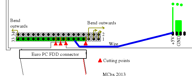
This drive should (except some minor problems with built-in LED) work in Euro PC, at least it worked in Euro PC II.
Here is a pinout of Euro PC II's mainboard floppy connector. I figured it out with schematics, manuals, WD controller datasheet and my tries with ohmmeter:
/SIDE1-> x x <- GND
/RDATA-> x x <- GND
/WPROT-> x x <- GND
/TRK0 -> x x <- GND
/WGATE-> x x <- GND
/WDATA-> x x <- GND
/STEP -> x x <- GND
/DIR -> x x <-NC ?
/MOTORB-> x x <- PWRON
/DSELA-> x x <- +5V DC
/DSELB -> x x <- +5V DC
/MOTORA-> x x <- +5V DC
/INDEX-> x x <- +5V DC (not used)
Board Edge ---> |
This pinout is used with ribbon cable (25 wires) with twist at the end (lines 3-9) going to connector to drive A. Without twist, a DB25 female port is attached for external drive B. That's why there are two MOTOR and DSEL signals.
The pinout of DB25 connector is:
1. /INDEX
2. /MOTORA (not for ext. drive!)
3. /DSEL
4. /DSELA (not for external drive!)
5. /MOTOR
6. /DIR
7. /STEP
8. /WDATA
9. /WGATE
10. /TRK0
11. /WPROT
12. /RDATA
13. /SIDE1
14-16. +5V DC
17. NC
18. PWRON
19-25. GND
MCbx, 2013

