![]()
![]()
![]()
![]()
![]()
![]()
![]()
![]()
![]()


All my content and ptohos

Making a simple LED display for PC casings
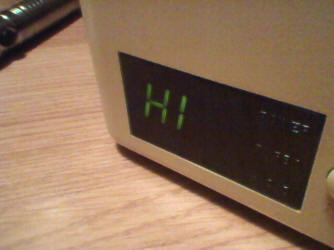
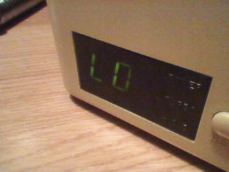
Some PCs come with a display which shows numbers, usually frequency or "HI/LO". They are usually not connected to anything important, only to power supply through a 2-pin 5V connector and to "Turbo" switch to toggle numbers shown. There were displays showing numbers coming from mainboard for some high-end 486 sets, but they are very rare now.
| Recently I got PC case which definitely had such display, but it was
removed. There is a window for display as well as marks of screws which
held it in place, but display with its circuit board is gone. I
decided to make a simple version, commonly used in newer cases, which
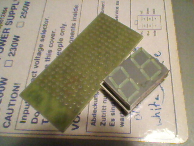
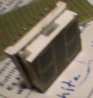
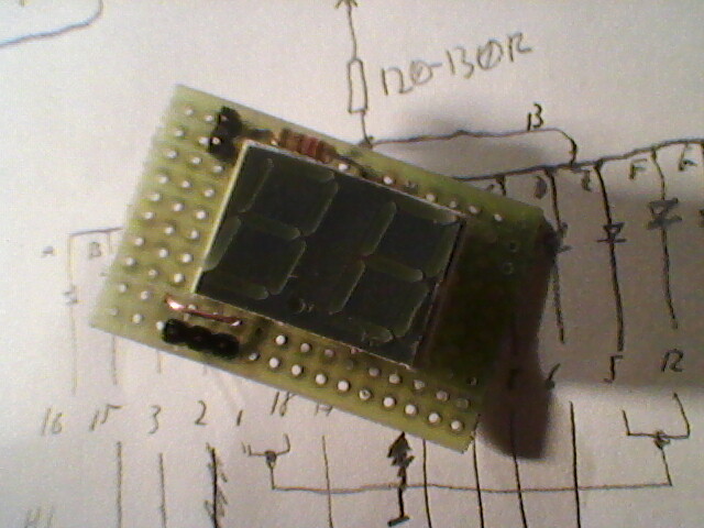
used not numbers, but "HI" and "LO" markings. You need: Note that I had only a bigger LED display, so I had to grind it down a bit. It can be done if you don't damage a PCB inside. The display is shown below: |
 |
 |
The LED display may be with common Anode or cathode, it doesn't
matter in this project. We will short both common pins together and feed
power through resistor. The most important thing here is to use a proper
resistor. Usually 150 Ohm is more than enough. If you need brighter
display, use smaller resistance, but don't overcurrent the LEDs as it
will make them fade dark very quickly. When HI is switched to LO, for a
very short moment, only 4 segments are lit up and this should never
cause them to burn out. If you have a totally unknown display, get its datasheet and figure out where pin 1 is. If it has been unsoldered, it may be handy to test LEDs at this moment to make sure that display works correctly. In most PC cases, LCD goes into small hole in plastic part and the transparent part is in its front. Make sure that display fits there. |
Display circuits used in PC cases have 2 connectors made of
Goldpin-type pins, with 2.54mm raster:
- One, 2-pin is 5V and Ground for power supply
- Second, 3-pin, comes from Turbo switch. Middle pin is toggled to left or
right one, depending on switch position. This will switch from HI to LO.
Now how to connect it: Common pins are connected together, then resistor and on its other side GND or +5V, depending on display type, is it common cathode or anode. Other pins have to be connected specific way:. Look at the scanned picture for example in common-anode display.
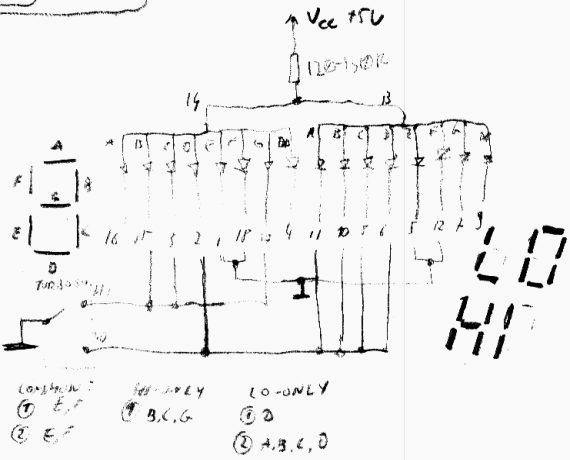
Pins 14 and 13, being common anodes, are tied together and +5V
power is supplied through resistor.
Pins 1, 18, 5 and 12 are tied together to ground making segments E and F on both
digits light all time.
Pins 15, 3 and 17 light segments B, C and G of first digit, making letter H with
segments E and F shining continuously. Letter I is lit all time.
Pins 2, 11, 10, 8 and 6 light segment D on first digit to form "L" and segments
A,B,C and D on the second forming "O".
Pins 16, 4, 7 and 9 are not connected. Pins 4 and 9 are for decimal points, 16
is for segment A in first digit, 7 is for G in the second. These LEDs don't
light both in HI and LO.
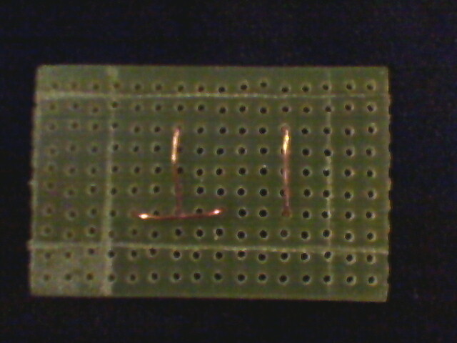
So having a schematic, it is only needed to draw how it will look in PCB, and then solder it. Remember not to cross many wires to minimize shorts and, if possible, conduct wires under display. This will make things easier. The first photo shows connection under display. Remember to put connectors on the SOLDER side as component side goes to casing.
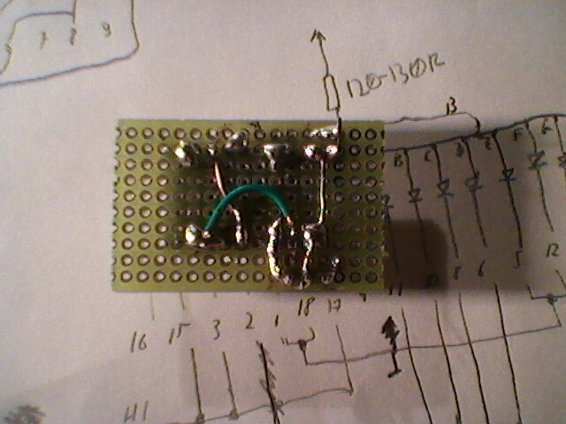
Finally, solder resistor and pins, then connect them to the
circuit. At all time make sure that there is enough space for screw which holds
the PCB in plastic part of case. At the last step, test everything and install
in case. Sorry for quality of pictures, I used my cell phone to take photos.
MCbx, 2017

