![]()
![]()
![]()
![]()
![]()
![]()
![]()
![]()
![]()


All my content and ptohos

Tuning a Sony/Dell CRT monitor using service mode
Some time ago I got a Dell P1130 21-inch CRT display. The only
problem with it, as previous owner said, was that the picture was "a bit
greenish" and that it has been opened once.
When I turned it on, I found that "a bit greenish" means that black is
dark-green. Quick messing with settings shown what happened - old Trinitron tube
had its age. Contrary to most tubes, Trinitron CRTs don't go darker with age,
but brighter. User then decreases brightness, and it's not possible to easily
"extinguish" green like other base colors. The idea was: Reduce brightness by
grid voltage trimmer.
But the thing is, that there is no trimmer for it. There are no trimmers in this
Dell at all. Everything is controlled digital way, by dedicated microprocessor.
But, according to information on BlurBusters forums, it is possible to hook into
service port called ECS port and act there. Small view in schematic and... it's
an ordinary RS232 port on TTL levels!
Getting inside
To get inside, in P1130, two screws on the bottom are removed. Then two locks in
both sides of monitor's plastic case are unlocked by sticking screwdriver there.
To open casing it's then only needed to press the upper part and open the rear.
In my unit I found that someone glued this part into the front one, probably
because all locks were broken. Well, if it's not possible to get this way, I
just looked at connector's location and drilled a hole in the rear of display's
case. It sounds terribly, but works. I got to 4-pin connector with on-PCB
description, from the left: TX, RX, +5V, GND.
So to hook up there, anything connected to computer and visible as serial port
on TTL levels can be used. Physical serial port with MAX232-like converter,
USB-Serial adapter, Arduino board,
dead badger... ok, the last one is incompatible with TTL signals :).
To connect through it, I used an Arduino Uno board because it works well as
USB_RS232 converter (contrary to Prolific ones which tend to fail in longer
transmissions). I removed the AVR chip and connected pins 0 and 1 to first two,
and GND to the last pin in connector. The only thing to remember is to cross
the Rx-Tx lines to make Rx connect with Tx and Tx with Rx (in Arduino, it's
the converter's Tx and Rx, NOT AVR's). That's all.
 |
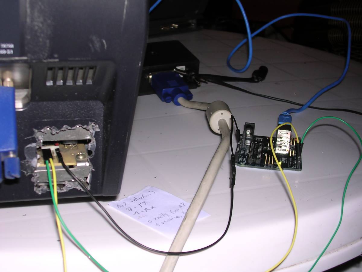 |
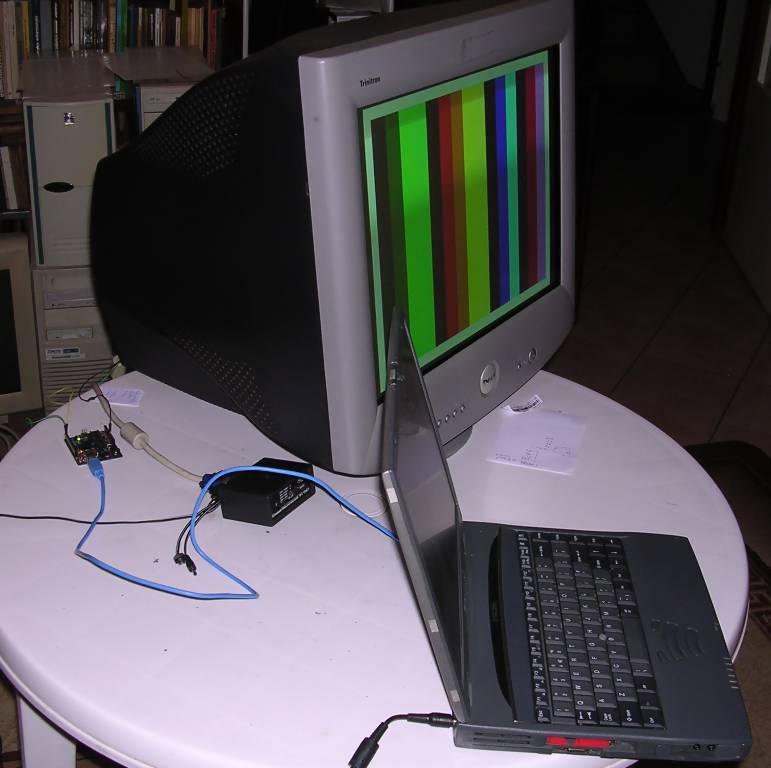
| Monitor, notebook and test picture generator, on the rear, the Arduino Uno board. | Rear of the display showing the drill and connection to Arduino module. |
The software
The software, called WinDAS, is in fact an early, unstable
and incomplete version, and is probably not an official program but a result of
some kind of quick reverse engineering - I highly doubt that any company would
use such unstable software in production. There is no complete "install" version
- the original release's
website recommended to assemble own distribution using dlls found in the
Internet. Text only briefly corresponds to actions and some toolbar buttons are
not connected to their functions. The program's engine is executing procedures
on monitor's microcontroller which correspond to different settings. Suddenly,
the procedures are made very well.
First of all, Set up->Config and there put SG to MANUAL, it
should stop complaining about SG ASTRO or similar stuff. SG is Signal Generator,
the thing connected to the second serial port which generates test signals on
its VGA port. You will generate picture manually for it, I recommend
Nokia
Monitor Tester program. Then set up the COM port to Arduino one. It should
stop complaining about MDL files if it has connection, it then just asks for
model.
Before changing any settings, please backup your configuration from monitor
using File->Save Data command! During copying settings, monitor will turn
itself off for a few minutes, this is normal, it comes on after copying is
complete.
 |
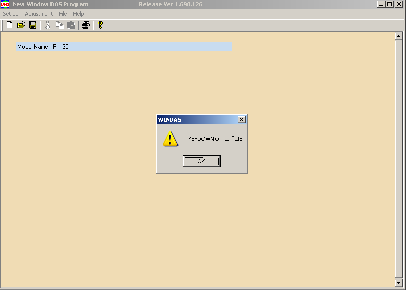 |
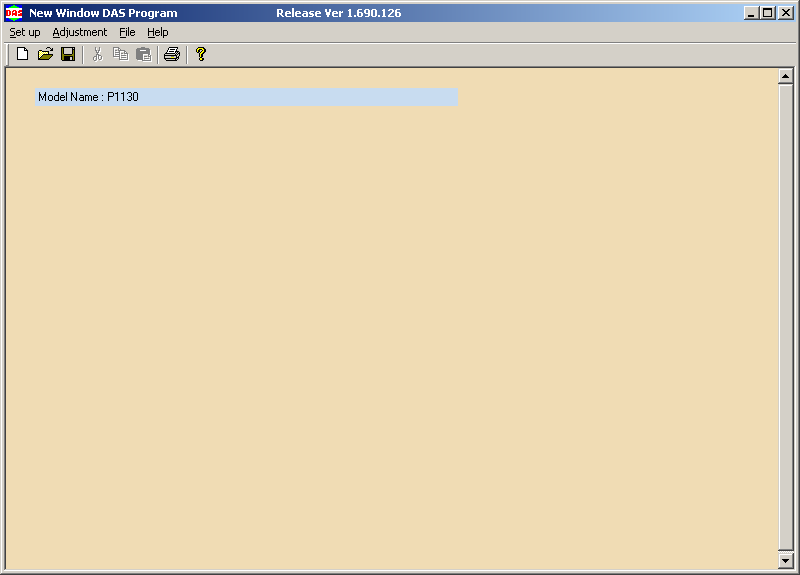
| Boot screen of the program - not much is shown in main windos | It's so debug version that it even reports some keys! Here are "Windows" and "Menu" keys. |
Quick course over this program:
There is an old overview
here but there is no exact description.
Fact_preset - After clicking this, a Factory Preset menu appears and you
can write monitor's factory settings.
Cont_SG - If a WinDAS-compatible picture generator hardware is installed,
it allows to control it.
Maintenance - Degauss, Aging test, power switch, software ID, factory ID.
Touch up - Rotation, pincushion, tilt, etc.
Procedure - Allows to perform a tuning procedure on display's driver and
it looks like it is like in-factory tuning method. There are also:
- Preparation for Alignment - asks for a few things.
- Alignment at VDC MODE
- Alignment at Maximum Frequencies
- Alignment at Minimum Frequencies
- Alignment at Mid Frequencies
- Prime Mode Alignment - these 4 procedures roughly correspond to each other
aligning geometry at different resoltions.
- Alignment of Factory Preset
- Landing Alignment
- Focus Alignment
- Convergence Alignment
- White Balance Alignment
- Final setting
DCnv - allows to launch convergence tuning procedure, see
http://dor-lomin.com/images/forums/hardocp/windas-conv/ for it. In some models
it may not work.
Failure - Views diagnostic points and test results of them. Refreshing
causes a power cycle during which monitor gathers information about start-up of
its components.
File menu:
Save data - saves config data from monitor to file.
Load data - Loads data from file into monitor.
MPU - Initialize microcontroller unit (anyone tried this?). Do it only if
replaced CPU is totally blank. Then you go setting by setting of a new CPU.
Help Menu:
Expert - allows to view .dat files and see registers contents. Do not
edit .dat files in notepad or WordPad - use hex editor or WinDAS will not
read them.
The biggest problem was that to decrease G2, a whole color calibration (White
Balance Calibration) must be performed from scratch and doing this without
colour meter is nearly impossible - I did it while comparing picture with
another Trinitron display, but this is not the proper method of doing it - too
many parameters for simple comparation.
Because we messed with brightness, convergence may fall apart. And convergence
in Trinitrons is something really hard to set. Typical convergence setting is
just making beams go in their spots. Of course it's changing with distance from
the center of screen, but it can be fixed by hardware just lineraly correcting
the convergence when the beam is far from center. In Trinitrons there are no
spots, there are horizontal columns, and convergence is highly non-linear. There
is a circuit called dynamic convergence, which monitors beam position and
applies corrections dynamically. The screen is divided to regions and by using
DConv it's possible to set the convergence for them if it works. If doesn't you
have to use Procedure convergence setting, but before this, a pincushion setting
must be set very precisely - the more precisely it's set, the better pincushion
convergence setting will be.
A good ending
To make the monitor's CPU remember changes as well as to make it free the
OSD (for programming settings, the OSD is locked and it may be left in a totally
locked state - displaying key icon on screen when buttons are pressed) it is
needed to finalize work with the monitor with the following steps:
- Give the display 1600x1200 signal.
- Adjustment->Procedure
- Select "Final Setting" and click SEL
- Confirm the signal, confirm tuning, confirm "Do you set the final
values". The procedure ends.
- Exit WinDAS dialogs by their apropriate Exit buttons, not with "x" in
the corner.
This is important especially when closing end of procedure and procedures window
- during this time WinDAS frees the OSD lock.
- Close WinDAS Window.
MCbx, 2017

