![]()
![]()
![]()
![]()
![]()
![]()
![]()
![]()
![]()


All my content and ptohos

Universal mouse
This mouse will work with:
-
- old, pre-ADB classic Macintosh computers (like Apple Mac Plus)
-
- Atari ST
-
- Amiga
-
- IBM PC, but only these with Bus Mouse / inPort Mouse add-on card
Currently it has been tested with my Mac Plus and it works very well. Other computers require other connectors, other pinouts and to make this mouse work with other computer you need only to change connector/pinout. Signals are universal.
WHAT YOU NEED:
-
- A computer (PC) ball-type mouse. Doesn't matter which standard, we will use only mechanics/optoelectronics.
-
- 8x10K resistor pack with common output
-
- 5-8x3K3 resistor pack with common output.
-
- A PCB-mounted variable resistor. 5K... should be good...
-
- One LM339 IC
-
- Two 100R resistors. One if you have a DUAL-detector mouse
-
- A 9-wire cable.
-
- a PCB veroboard... maybe...
THEORY OF OPERATION
There are many types of computer mice. But all computer mice
types can be divided to three categories:
-
Mice with analog output - the most known analog-output mouse was the mouse in Engelbart's NLS (oN Line System) shown in December 1968. They're not used since 1970's, when "mafia" from FCC forced manufacturers to buy more equipment and to make transferred signals digital (there was a "crusade" against using analog signals in transfer since 1980s!).
-
Mice with digital-level waveform output - which feeds the computer with impulses produced according to mouse moves, in phase dependent of direction. These signals must be converted by computer's circuits. We're going to make this one.
-
Mice with digital data output - which supplies the computer a complete, ready-to-use data about moves in form of data packets, easy to send/receive and not requiring any other analog-digital processing. Today's PC serial port, PS/2 and USB mice are these. And ADB, they're too.
This tutorial explains how to make a digital-level mouse by re-working a typical cheap computer mouse. Ball mouse, NOT an optical one. Re-working an optical mouse requires a microcontroller.
Our mouse must make square impulses as it's moved. Because our computer must know is it moved left or right, there must be two waves in phase, generated on two wires. To make these impulses we're using impulses generated by mouse's optomechanical part. And because we get only about 2.5V from it, we'll use a LM339 quad voltage comparator - which means it will put 5V on its output if the input voltage is greater than other voltage applied, and 0V if it's smaller. It will generate impulses from all optical detectors.
If you open a computer mouse, you'll see:
- A ball.
- Two shafts, which move two discs.
- Optical part
- Electronic part.
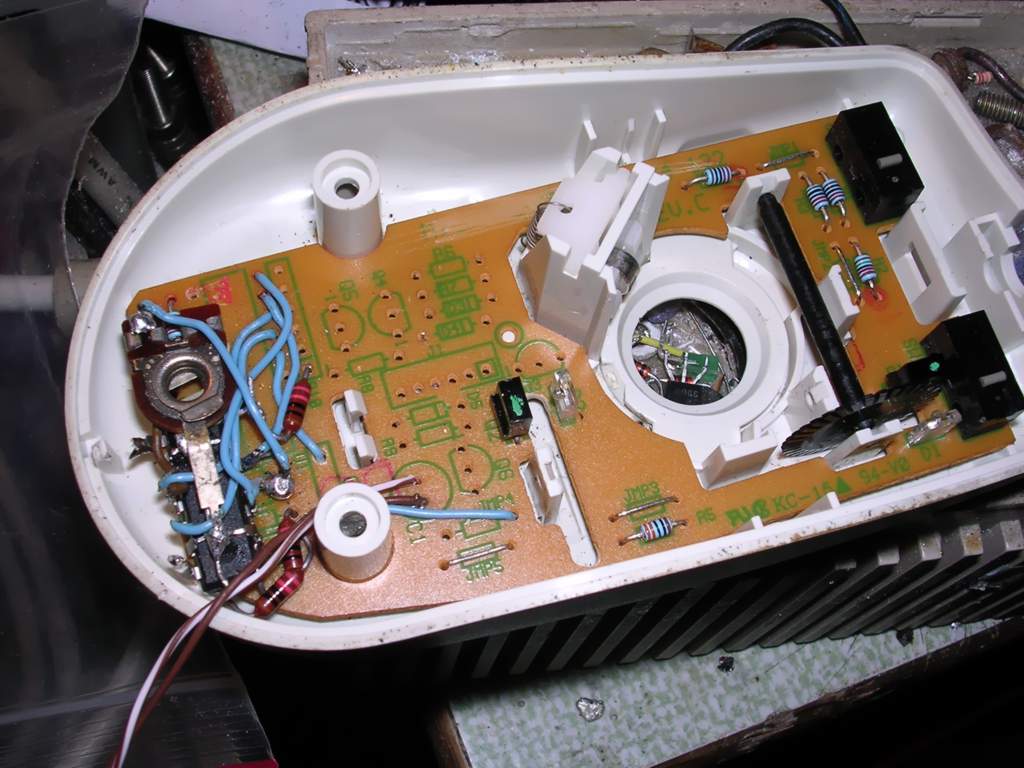
You have to remove everything from PCB EXCEPT optical LEDs and detectors (leave buttons too). The PCB must be left, because LEDs and detectors are there. Now cut the tracks to make connections easier (or use existing ones to now-desoldered proprietary chip).
There are two kinds of optical subcircuits. The most common in cheap mice are DUAL type, which means that one infrared LED (the component with two leads) lights to one component, which consists of two photo-sensors (three pins), and this pair is for each of two discs. Summing up: Two LEDs (2 discs), 2 sensors, which are 4 in fact. The other, SINGLE type, uses 4 LEDs and 4 optical detectors, two pairs for each disc usually on both sides. If your mouse is SINGLE, you have to make it DUAL by connecting two photodetectors with one pin (the same on two detectors).
In fact, the thing is easier than it looks. You have to make this inside your mouse:
This is a very simple thing, but this schema is screwed up. If you have a DUAL, you have only two LEDs, so do not build one of these LED segments. About the polarity of PHOTOdetectors - discover it. Power up the LEDs (you can use existing resistors or add one) and measure resistance on photodetectors while rotating disc slowly. This large thing labeled "CONN-SIL9" is your cable coming out from mouse. 1 is 5V, 9 is Ground. 6, 7, 8, are the buttons. All other pins are movement output pins (X1, Y1, X2, Y2...). To power it up, you need any regulated 5V DC power supply. Old computer PSU, cell phone charger - this circuit isn't much demanding.
If you successfully made this thing inside your mouse, it's time to tune it. It's good to make it in a dark room (to reduce incoming light), but not in a complete darkness (to see what you're doing). Power it up (do you remember that you need to power the chip too? pin 3 to 5V, pin 12 to ground, as shown on a schematic!), connect a voltmeter to one of mouse's outputs. With RV1 set the voltage as low as possible and slowly turn it higher, while moving a disc corresponding to measured output. MOVE IT SLOWLY. There are 30-36 windows, which makes photodetectors detect the motion. If you see the pointer of voltmeter going to about 5V and going back quickly - stop turning RV1, it's tuned. Check other detectors and, if they need different tuning (really old and tired mice) find a common point.
Here is a photo of this mouse inside.
I prepared a quick-and-dirty PCB layout to quickly put this into a mouse... There is one modification, RV1 is connected to the ground, not RP1, but it's not a big difference and gives a bit smaller current consumption.
 |
 |
| PCB drawing (view from component side - OK if you use thermo-transfer) | Components diagram |
PINOUTS!
To connect this mouse to computers
Macintosh Plus:
 (at the computer) - MALE plug
at the mouse cable.
(at the computer) - MALE plug
at the mouse cable.
| Pin | Name | Notes |
| 1 | CGND | Chassis Ground |
| 2 | +5V | +5V to mouse |
| 3 | CGND | Chassis ground |
| 4 | X2 | Movement Line |
| 5 | X1 | Movement Line |
| 6 | n/c | not connected |
| 7 | BUTTON | Connect all 3 here. |
| 8 | Y2 | Movement Line |
| 9 | Y1 | Movement Line |
Amiga:
 (at the computer) -
FEMALE plug at the mouse cable
(at the computer) -
FEMALE plug at the mouse cable
| Pin | Name | Notes |
| 1 | V | Movement Line |
| 2 | H | Movement Line |
| 3 | VQ | Movement Line |
| 4 | HQ | Movement Line |
| 5 | BUTTON 3 (M) | Middle button |
| 6 | BUTTON 1 (L) | Left Button |
| 7 | +5V | 5V for the mouse |
| 8 | GND | Ground |
| 9 | BUTTON 2 (R) | Right button |
Atari ST:
(at the computer) -
FEMALE plug at the mouse cable
| Pin | Name | Notes |
| 1 | XA | Movement Line |
| 2 | XB | Movement Line |
| 3 | YA | Movement Line |
| 4 | YB | Movement Line |
| 5 | BUTTON 3 (M) | Middle button |
| 6 | BUTTON 1 (L) | Left Button |
| 7 | +5V | 5V for the mouse |
| 8 | GND | Ground |
| 9 | BUTTON 2 (R) | Right button |
PC MS/Logitech Bus Mouse or MS InPort Mouse
This is a hard one... I know there's a mini-DIN 9-pin connector, but I don't know the exact pinout. Here are two pinouts I got from an internet:
Pin 1- SW 2 Mouse button 2
Pin 2 - SW 3 Mouse button 3
Pin 3 - GND Ground
Pin 4 - XB X position
Pin 5 - YA Y position
Pin 6 - YB Y position
Pin 7 - SW1 Mouse button 1
Pin 8 - +5 V Power
Pin 9 - XA X position
And the second one (from http://www.cs.rochester.edu/~kparkins/pinouts.txt ):
|-----------|----------------|---------------------------|--------------------------|
|Wire Color |   Mini-DIN Pin |  Logitech P-Series Signal | Microsoft InPort Signal  |
|-----------|----------------|---------------------------|--------------------------|
|Black      |       1        |        +5V                |          +5V             |
|Brown      |       2        |         X2                |           XA             |
|Red        |       3        |         X1                |           XB             |
|Orange     |       4        |         Y1                |           YA             |
|Yellow     |       5        |         Y2                |           YB             |
|Green      |       6        |        Left               |           SW1            |
|Violet     |       7        |       Middle              |           SW2            |
|Gray       |       8        |       Right               |           SW3            |
|White      |       9        |        GND                |        Logic GND         |
|SHIELD     |     shell      |      Chassis              |         Chassis          |
|-----------|----------------|---------------------------|--------------------------|
They may be just counted in a different way.
MCbx, 2010
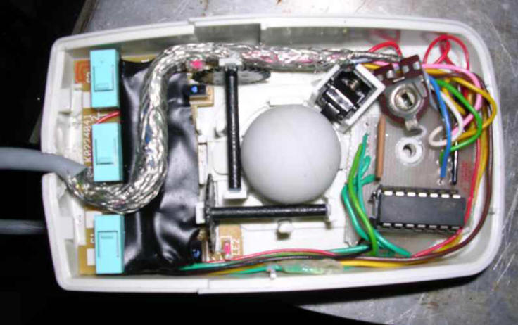
[UPDATE 10.2013]
Working prototype with LM324 IC (the same schematic, only ICs pins are different)
- photo before it was secured with hot melt glue: