![]()
![]()
![]()
![]()
![]()
![]()
![]()
![]()
![]()


All my content and ptohos

Numeric keypad for C64
Many years ago, N. Coplin released a circuit and a software program to attach a homemade numeric keypad to Commodore 64. The archive containing schematic and software driver can be downloaded HERE. Schematic diagram of this device is shown in the picture on the right. It's a very difficult thing... You can get scared of logic gates and lots of connections between them. To make these chips work, an extrenal power supply is also needed. It's probably possible to build it on a veroboard, but using a normal PCB it will require at least 2 layers of copper to connect every piece of logic. But if we look further into this thing, we'll see that's only a binary encoder. We can make it simplier. To make the keypad working, loading a special software "driver", included in archive, is needed. Writing special "drivers" may make this device work in other 8-bit computers.
There is one more thing - C64 scans the keyboard in a strange way and is not electrically compatible with diode matrix, so when none of these keys are pressed no output lines must be loaded. If they are, a whole key lines will be swapped, for example typing QWERTY... you'll get: ERERTY..., ASDFG... will change to DFDFG... etc. That's why there are 74HC05 open-collector inverters in the last stage of the circuit. And we must do the similar thing.
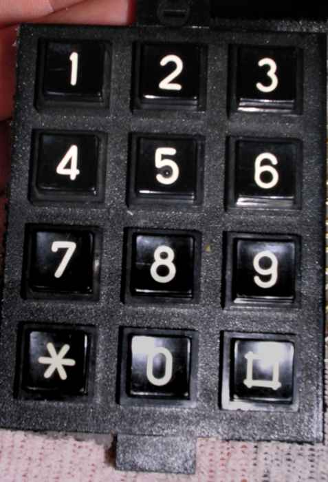
Switches - The keypad itself
I used a typical numeric keypad from an old phone. It's a matrix keyboard, which means it's a grid of wires connected by switches. If we have a 12 keys, there will be only 7 wires coming out from the keyboard (3 columns, 4 rows). It's practical in a complex digital devices with keyboard scanning routines, but it's useless in this device. This keyboard must be a normal key set which shorts every key's wire to the common one (in our circuit: ground) - 12+1=13 wires.
To re-work the matrix keyboard we must:
0. Determine which wires are for columns, which are for rows.
1. Connect all columns/ all rows together (choose this with fewer wires)
1a. Get to the keyboard's PCB, and after modifications put it back together :)
2. Cut the tracks between switches to make every floating wire lead to one switch. Cut tracks connecting other switches in a columns/rows. Do not touch connected wires' tracks.
2a. Drill holes near removed tracks, file the tracks with sandpaper.
3. Solder additional wires to the tracks. Make the solders as flat as possible, and as close to the hole as possible. Use a thin wire.
Here is a simple diagram what to do:
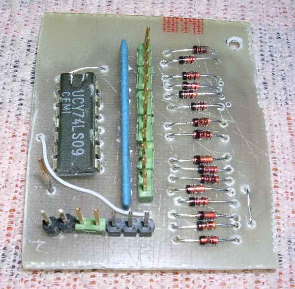
OK, Finally, here is the schematic diagram of the keypad driver. It's quite self-explanatory, the last open-collector stage is realized using 74LS09 quad AND gates IC. It MUST be 74LS09, because there's a limited load we can draw from C64's joystick port. RP1 is a 12x20KOhm resistor pack, you can use any value from 15K to 47K. Diodes are a typical signal diodes, in my case 1N4148. Keypad's key wires are connected to J2, J3 is its common ground. C64 cable goes from J1 (SIL) as shown in the table and ends with female DB-9 connector (DB9F). Its pin numbers should be OK, as they're etched on the connector's plastic part.
BEFORE connecting to C64 check if there aren't any short-circuits, and, if possible, measure the current took by a keypad. It shouldn't exceed 50mA. If you fry something inside a C64, it'll probably be a CIA ciruit. The keypad is compatible with Coplin's version, so after connecting keypad to C64 you must load Coplin's driver to make it produce numbers.
PCB layout:
 |
 |
| Looking from component side (good for thermal transfer print) | Components placement.
|
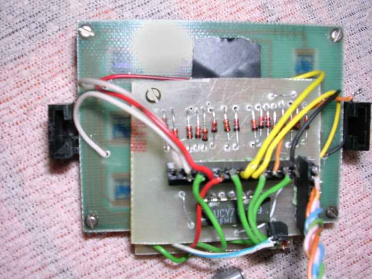
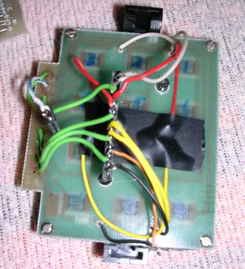
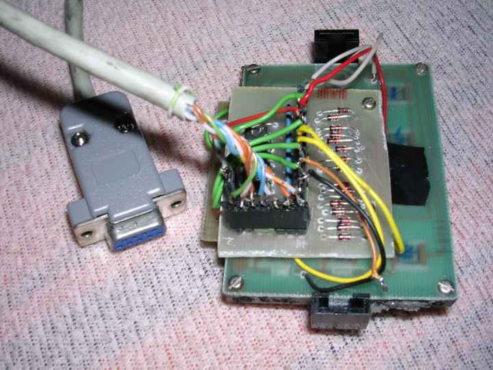
Photos of a complete device:
 |
 |
 |
 |
 |
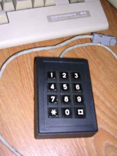 |
| A board | Board and keypad | Front of the keypad | Matrix keyboard-normal keyboard rework. | Back of the keypad. | Final version |
MCbx, 2010

