![]()
![]()
![]()
![]()
![]()
![]()
![]()
![]()
![]()


All my content and ptohos

Monochrome picture in old VGA boards fix
This thing plagued me for years and I finally decided to do
something with it. Monochrome, grayscale or no picture at all when using old VGA
video boards with KVM switch or just a new monitor. This happens in older,
ISA-based Trident and WD video boards (or on-board chips), usually when an
electronic KVM switch is used. The problem may be related to two things, and if
the test does not show this problem, it means that it's something else.
Short version:
If shorting pins 4 and 11 in VGA plug to ground doesn't work, try to short R, G
and B to ground through 100R resistors. OK, and now we go to explanation.
The test
When the problem is related to passing picture through KVM switch, to determine
is the problem caused by misdetection of the display, boot the computer with a
proper monitor connected to see the proper, color picture. Now with machine
still running disconnect the monitor, connect it to KVM's output and connect
KVM's input cable to the computer. Set the KVM to the computer. If the picture
is shown properly, it means that there is a proper pass-through but the problem
is in detection of monitor. If there is no picture, usually the KVM cannot
transfer properly signal from video board (or maybe it is a "high-end" of early
90s and has a real-time auto-detection?).
If the problem is not with KVM, the same thing can be done with different
monitors. Usually booting without display should also give monochrome/grayscale,
but may be worth a try.
Solutions
There are two most common ways for the video board to determine is the monitor
connected or not. The best try is to check the first one, then the second using
an adapter, and then build the final version of the adapter.
The first method uses ID bits, which are usually pins 11, 12, 4 and 15 in 15-pin
socket, respectively ID0,1,2,3. These bits came into use in 1990s, but sometime
in mid-90s they got replaced with VESA DDC which crammed a whole serial bus
there. Many DDC video boards should fallback if they sense ground in some pins.
Generally to tell the video board that the monitor is connected, you have to
short some pins to ground. Typical shorts are:
Nothing connected - No monitor.
Pin 12 connected - Monochrome monitor, uncapable of 1024x768
Pin 11 connected - Color monitor, uncapable of 1024x768
Pins 4 and 11 connected - Color monitor, capable of 1024x768.
The closest ground is in the shell of a plug, it's not a very good ground but
sufficient.
So shorting pins to ground tends to work with old, rather 16-bit and maybe VLB
boards, not the early ones for 8-bit ISA or WD on-board chips.
The second method is a bit more complex in video chip's structure but is
historically the first one. The video chip checks electric current drawn from
each pins R, G and B. With this information it gives the proper picture. It is
assumed that these early monochorme-only monitors will draw only from one line,
the grayscale will not draw much from all lines and colour will draw more from
all 3. The problem here is that digital KVM may use much less current from these
pins than current meaning that the color monitor is connected. This usually ends
with grayscale picture or no picture at all.
To fix this, it is needed to connect resistors between R, G and B lines to
ground. The value of resistors should be around 100 Ohm. Theoretically it should
be 75 Ohm, but we include the small current KVM draws and some reserve so we
need to draw less.
Building the adapter
We will need two VGA connectors for soldering wires to them (not the PCB ones).
One male, one female. The adapter should be short not to introduce
interferences. First, orient these plugs back-to-back and solder the protruding
middle row of connectors to each other. Preferably do not keep them on solder
only, use short pieces of wires where you can. Then, soldering small pieces of
wire, connect pins 1, 2, 3 and 5, as well as, in the other side, 13 and 14
making a 1:1 pass-trhough for them. The best thing now will be to use some
longer screws and nuts to secure this construction not to break it. This should
be tested with ohmmeter (and may even work in computer without any visible
effect on picture).
Now, solder pins 4 and 11 of male connector to its shield and try this in a
computer. Test the thing. This fixes the first method of detection.
If this does not solve the problem, you can solder a longer wires to GND and
other ID bits and try connecting various lines to ground the other way, but I
found that most of these early 90s video boards will still not give proper
results - they implement a second method of detection and it's time to try the
second fix.
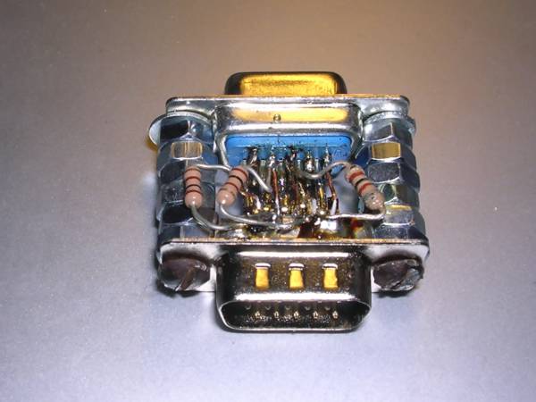
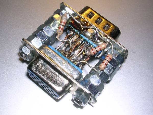
Remove additional wires from ID pins. Use three 100Ohm resistors soldering them
between R, G, B lines (pins 1,2,3) and ground (I know that's not a good
practice, but there's a metal shield nearby and grounds for R, G and B only
should be separate, usually they are not). This should "emulate" monitor
connected all time.
Below there are photos of a ready adapter I use with my KVM. It is a good
practice to secure this with some resin, cover it with a grounded conductive
foil outside and insulate one more time, but for this 640x480 given by early
boards shielding may not be needed.
MCbx, 2019

