![]()
![]()
![]()
![]()
![]()
![]()
![]()
![]()
![]()


All my content and ptohos

DIY ZX Spectrum keyboard membrane / foil.
INTRODUCTION
The biggest problem in a rubber ZX Spectrum is its keyboard - because of its construction it wears out very quickly. If someone lifts off upper part of Speccy's case too enthusiastically connections between keyboard membrane and PCB may break. If it broke near PCB, you can cut foils and try to make a new "plugs" sticking hard pieces of plastic ripped from damaged part back to ribbons. I can tell you that it works, but if it broke near the keyboard, you have little chances of repairing it - or you can make new foil. In Poland there were a few methods of making a home-made membrane. One of them was to etch a PCB and solder a small pieces of springing metal as contacts. This type of membrane has a short lifespan because metal springs deform and close circuit when no key is pressed. Using a flat tact switches is probably better but has two flaws: it's too expensive comparing with new membrane's price and it requires lifting Spectrum's metal part using a pre-made frame around keyboard - so that Speccy looks very bad. Construction shown here employs something like a remote controller's keyboard inside Speccy.
WHY NOT SPECTRUM+?
ZX Spectrum uses 5x8 multiplexed lines for keyboard. 5*8=40, Classic Spectrum has 40 keys and it can't have more. Spectrum+ has 58 keys, because they involve symbol shift combinations. The problem is with these additional keys - they use 3 conductive layers of membrane, two gaps shorted one after another during keypress. So pressing for example an arrow key is in fact pressing a symbol shift key first and corresponding key next. It's hard to reproduce this with our single sided PCB technology. You can build a keyboard to Spectrum Plus, but without these additional keys.
1. What you will need:
- A thin copperized PCB laminate - as I write thin I mean 0,2-0,4mm. With
thicker you'll have problems with cutting and installing it in Speccy.
- Your favourite PCB etching set - I use thermal transfer method and B327 (sodium
persulfate) which is quite safe to skin and clothing.
- A flat ribbon cable, for example from a floppy drive cable. In exact one
ribbon of 5 and one of 8 wires, about 12cm each.
- Soldering rosin (colophony) dissolved in alcohol.
- Sharp knife and scissors to cut thin PCB, Soldering iron, soldering alloy.
- A thin magnet wire.
- A
set of conductive rubbers used to re-generate remote controllers. Mine came from
"AG Chemia". Set contains 100 round rubbers and silicone glue.
How to make PCB?
![]() Here you have
PDF which MAY or MAY NOT be printed properly.
Here you have
PDF which MAY or MAY NOT be printed properly.
![]() Here you have a 300
DPI PNG image of a board.
Here you have a 300
DPI PNG image of a board.
Note that they're mirrored to be suitable for thermal transfer process. If you use another technique flipping it may be needed.
Before making PCB, make sure that you'll get an accurate width of a keyboard. Because I've made a few corrections to few Spectrums you should make a test print on a thin paper, cut it, fit it into Speccy's keyboard membrane place (printed tracks down), carefully align holes on sides to the bolts pressing them through the paper, and finally press the other ones with a rubber part to get through paper. Now you should check is everything OK: rectangular holes (rubber keeping bolts), thin round holes (round bolts) and keys (key mosaic is under a rubber part's key - if you can't see it through the paper mark it with permanent marker). If it isn't good, making width 1% smaller or bigger may solve the problem.
If you etched the board without mistakes, you should paint it with rosin solution and let it dry. Now let's cut it properly: Cut copper planes, separated bars and a measuring rectangles off. You need these bars to connect your keyboard to Speccy. Measuring rectangles usually doesn't work in so detailed PCB because of line thickness, so don't trust them too much (In fact, they're good over 1,5mm). In every stage you should check the alignment of PCB in your Spectrum's case and make alterations if needed. Why? For example during thermal transfer thermal expansion of paper and PCB is different so we loose some dimensions accuracy.
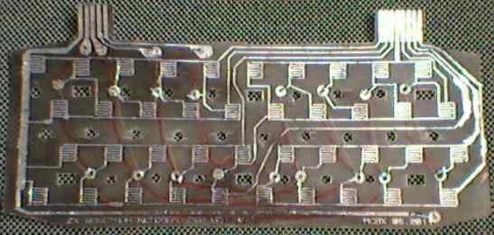
The next step is to cover every track with solder alloy and not to make shorts. It's important because copper oxidizes quickly and tin prevents from it. Check these shorts with an ohmmeter and cover these separated bars too. Now cut out round holes and rectangular ones. To make round ones (only thin outlined ones!) it's good to use a tool for making holes in belts. Rectangular ones may be cut with a sharp knife. To end machining a board make a small holes in thicker outlined spots. You should end up with something like this:
OK, you'll install the board with copper facing, so now you need to connect thick holes by magnet wire on the back side. Do it this way:
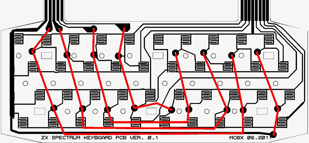 (click to enlarge, this is NOT a mirror like the PCB images - it's shown from
tracks side!)
(click to enlarge, this is NOT a mirror like the PCB images - it's shown from
tracks side!)
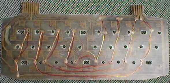
Because insulation of the magnet wire isn't rigid, don't cross wires. For a series of points you can use one long wire bent to get into holes, but peeling insulation will be a bit difficult. Finally secure the wires with sticky tape. The board from back side should look like this:
A close-up:
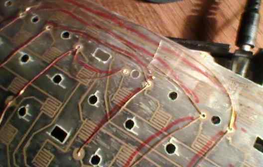
One more thing, magnet wire IS insulated by a thin layer of enamel, so peel off insulation on the ends of wire before soldering.
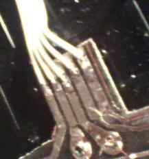
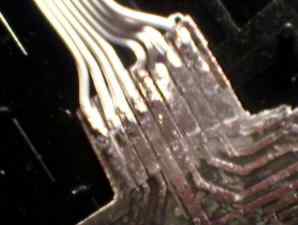
Now cut about 12cm of ribbon cable. Split its ends and peel them off insulation. Cover it with tin using soldering iron (it's good to apply rosin before). Now solder them to PCB terminals. Do this thing with 8 and 5-wire ribbons. Here are two photos of PCB terminals with ribbon cables. One magnet wire solder is visible too (magnet wire shows through thin PCB):
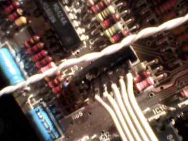
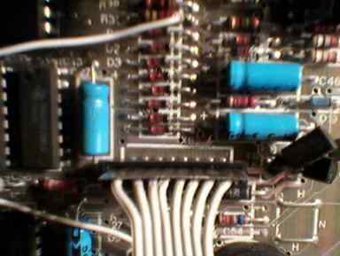
Now solder these blocks of bars you previously cut from board to the other side of ribbon cables. Align the keyboard PCB tracks facing you with ribbons running straight up. 5-wired left one goes with bars facing you but the right one goes reversely - back side facing. It must be done this way to plug into Spectrum connectors (you can make sure by peeking at your Speccy mainboard). Here are two photos of these blocks fitted to mainboard.
OK, get your new PCB to Speccy's case (if you can't push solder points through the aperture, pry it a bit wider, but not too much) , plug it in (I hope you checked it for short circuits) and test it by shorting every key with some piece of metal. It should work now.
MODIFYING RUBBER PART
This is quite easy. Just stick remote control rubbers in the center of "+" under every key. Here's a nice photo how it sholud be done:
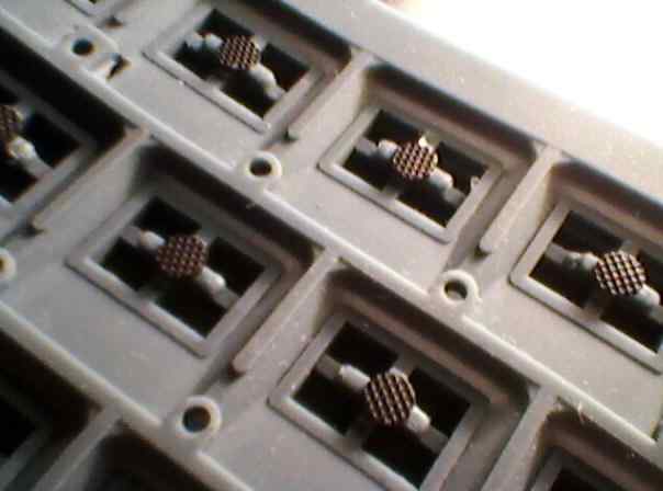
Avoid touching these pads too much, as they may loose their conductivity. To press the rubber part use a flat metal slab (baking form or sth.) loaded with something heavy. Leave it for longer than the glue hardens because of no air flow there.
Now there's only one thing to do - put the rubber on the PCB and test the complete set!
MCbx, 2011

