![]()
![]()
![]()
![]()
![]()
![]()
![]()
![]()
![]()


All my content and ptohos

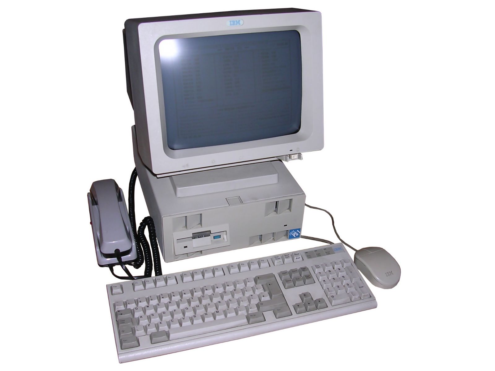
IBM PS/1 Model 2121
IBM's PS/2 line of computers was targeted towards
business and high-performance applications. In 1990 IBM released a new
line of low-end computers for home applications. First units, Model
2011, had 286 but later ones had 386 and even 486. Most PS/1 types had
normal ISA slots instead of MCA and had simpler design. To make
computing easier, early PS/1 computers have parts of software in ROM.
It was possible to fit many upgrades to PS/1. RAM was expandable with
special card, it was possible to add expansion boards using 2 16-bit ISA
slots, there was also expansion connector in the rear. It was possible
to use different mouse and keyboard. IBM offered "Enhanced" mouse and
keyboard versions. Such keyboards were smaller and mice more ergonomic
than standard ones.
| Manufacturer | IBM |
|
| Origin | USA | |
| Year of unit | 1991 | |
| Year of introduction | 1990 | |
| Class | AT | |
| CPU | Intel 80386SX | |
| Speed | 16MHz | |
| RAM | 2MB (expandable with proprietary card) | |
| ROM | PC BIOS, software launcher (called 4-Quad menu) | |
| Graphics | VGA | |
| Sound | PC Speaker | |
| System expansion bus | 16-bit ISA (2 slots) | |
| Floppy/removable media drives | 1.44MB floppy disk
drive (proprietary connector)
|
|
|
|
||
| Hard disk: | 42MB IDE (PATA) |
|
|
|
||
|
Peripherals in collection: |
||
| Other cards:
|
DYSP (Dyspozytorka) connectivity/telecommunication card | |
| Non-standard expansions: | Telephone connectivity | |
| Operating system(s): | MS-DOS |
My units are from army surplus, in which they were used as communication devices. They were equiped with special ISA expansion cards giving telephone connectivity and simple modulation for transmitting messages. This system has been used in early 1990s until 2000s in some Polish hospitals. I've made an attempt to describe system components. The systems of course came to me fully sanitized, so if you have a software to operate these cards, you can drop me a line.
| Contents: | Starting, usage | Pinouts | CRT Disassembly | Links |
Starting
This model has quite big problem with starting when CMOS
backup battery is exhausted. Generally when battery is dead, you will
end with errors 16x (161, 163) and booting to ROM. In most units hard
disk doesn't contain OEM software (yet it can be found on backups, see
links), so ROM software launcher won't launch anything. If you press
Ctrl-Alt-Del then you will restart system and it should boot from hard
disk. Nevertheless, it won't boot from floppy when started from dead
battery state.
If you have a dead battery, RTC may just not tick - sometimes time set
doesn't change, it's the main symptom of bad RTC battery. The battery is
located on the mainboard under expansion port PCB. Disconnect ribbon
cable and you have it.
To make the system boot from floppy, you have to boot DOS somehow and
run CUSTOMIZ.EXE program. This program changes settings responsiible for
starting and booting the computer. It allows to select boot options,
e.g. to try floppy, then hard disk skipping ROM. To run my unit, I had
to prepare hard disks in an other computer and add CUSTOMIZ.EXE and
CONFIGUR.EXE. The second program, CONFIGUR.EXE is for changing
parameters of ports and integrated devices, like "Integrated
peripherals" section of Award BIOS Setup program.
Power supply pinout:
The system has power supply and speaker built in monitor. Monitor is a
standard VGA with speaker and DC power supply. The pinout is shown
below:
(male connector in the computer)
1,2,9 - +33V DC
3,7,10,11,14,15 - GND
6 - PC Speaker out
The voltage is 33V (some sources: 32V) DC, I don't know current, but if you try to run it, give it 1,5A or more and try monitoring 5V and 12V in HDD Molex plug. The computer has a switching converter which makes all needed voltages from 33V DC.
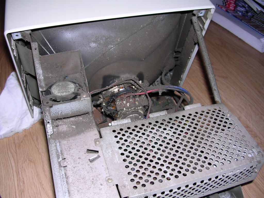
If you have this computer, remember to clean CRT monitor inside. This monitor has a fan built-in, so after few years of operation you may end with something like this:
To open a monitor, disconnect it from computer and place
it on the screen using carpet, cloth or other protective pad.
You also need a special Torx screwdriver with a hole inside.
Remove two such screws from the upper part.
Now squeeze two latches and lift the stand from monitor. You will see 2
Philips screws, after removing them you can remove monitor stand's base.
Then you will see chassis inside.
Now remove 3 Torx screws and lift the rear cover upwards. Be careful
with rubber pads, as they may fall off the cover. Carefully clean the
bottom and place the monitor on it. All screws inside are Philips type.
Remove 5 of them and lift the part with holes off the chassis. Then you
can clean wires and parts of PCB. Use a brush and vacuum cleaner.
To remove fan, unscrew it from the left side. Now clean power supply as
much as you can, it is quite difficult to get inside but brushing
through holes is sufficient. Remember to clear (using vacuum cleaner)
air inlet in the bottom-rear, as there usually is much dust in it.
https://ps1stuff.wordpress.com/ - Earlier model 2011 page.
There are diagnostic disks, Configuration tools and OEM HDD contents to
download, as well as emulator with quite realistic GUI.
http://ps-2.kev009.com/pcpartnerinfo/ctstips/c586.htm -
Information about models
http://ps-2.kev009.com/pcpartnerinfo/ctstips/3ab6.htm - Main
information about PS/1 computers.