![]()
![]()
![]()
![]()
![]()
![]()
![]()
![]()
![]()


All my content and ptohos

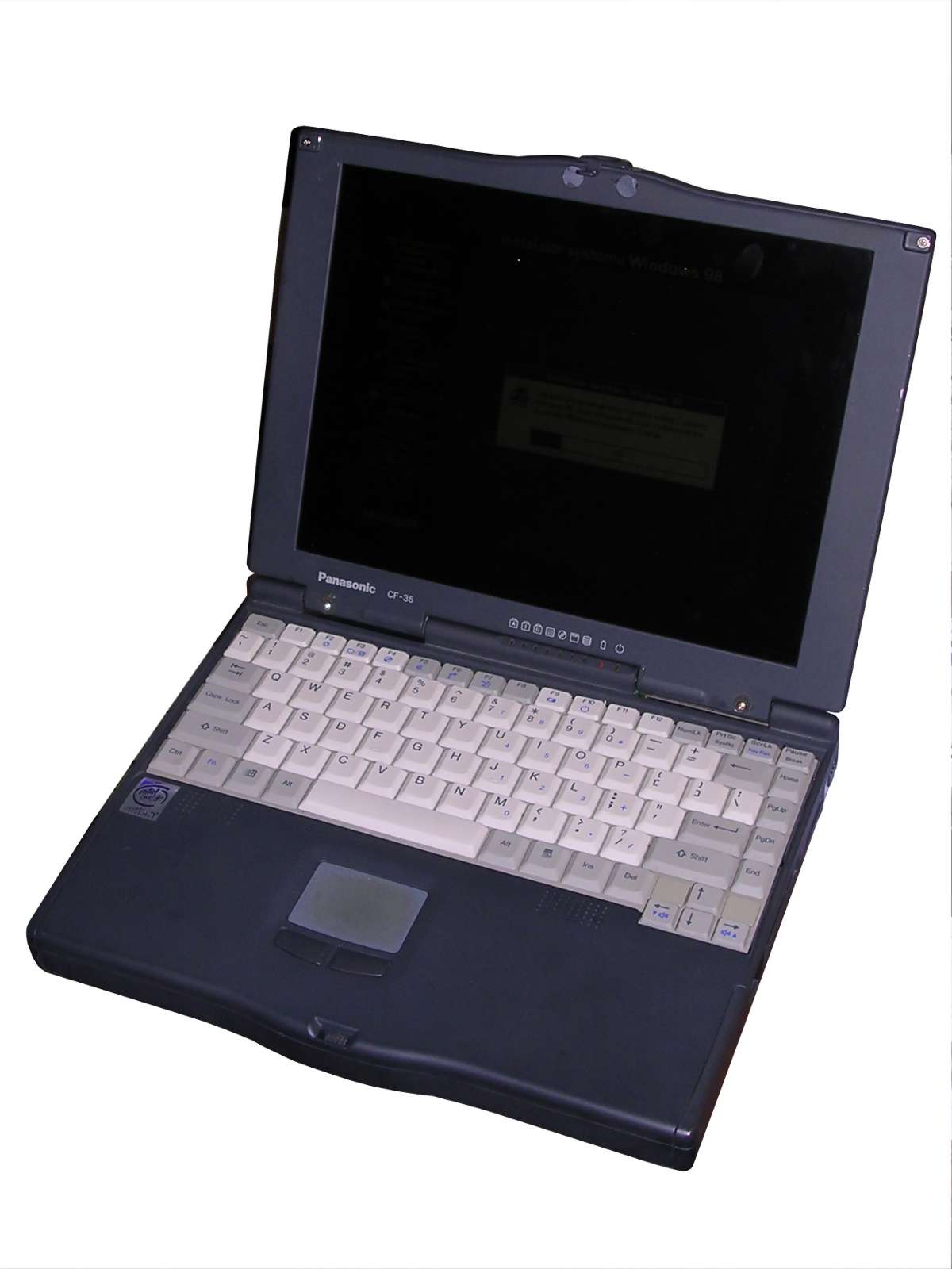
Panasonic Toughbook CF-35
In 1990s Panasonic, division of Matsushita Inc., was
known hardware manufacturer. Their Toughbook line was focused on a
rugged notebooks which could withstand harsh environmental conditions.
However, so durable computer was heavy and large. In 1997, Panasonic
released two interesting machines: CF-25 and CF-35. While CF-25 was a
heavily rugged unit, CF-35 was known as "slimline" - smaller, lighter,
but less durable. Magnesium alloy has been substituted with metallized
plastic, with a thick coating to prevent scratches, and the casing has
no humidity and water protection known from Toughbooks.
The computer has quite nice hardware inside for its age: A Pentium MMX
200MHz (in other versions: 150MHz) with a small fan which turns on
rarely, 32MB of RAM built-in (expandable by EDO SO-DIMMs) and a NeoMagic
graphics adapter. The LCD (TFT) is also nice, 16bit 800x600 which in its
time was definitely not a "budget". Inside, it is possible to install a
floppy drive or probably CD-ROM in a bay. I/O ports are also totally
sufficient: Serial, parallel, infrared and even USB. It came with 2 or
3GB hard disk. It has also a small touchpad, which was not common in
1997.
The problems were mostly related to unfinished CMOS part which caused
lots of troubles when it came to re-configuration.
| Manufacturer | Panasonic |
|
| Origin | Japan | |
| Year of unit | 1997 | |
| Year of introduction | 1997 | |
| Type | Laptop, PC | |
| CPU | Intel Pentium MMX 200MHz | |
| RAM | 32MB (upgradeable with EDO SODIMM) |
|
| Floppy Disk | In a bay | |
| Hard Disk | Originally 2 or 3GB, IDE 44-pin | |
| Other media | CD-ROM drive in a bay | |
| Graphics and display: | 800x600, 16-bit color LCD, TFT, 12.1" |
|
| Sound: | Stereo, speakers built-in. | |
| Keyboard and pointing device: | Small PC keyboard without numeric
part. Touchpad with buttons. |
|
| OS: | Windows 95 | |
|
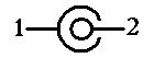
Power supply:
1 - Ground |
||
| I/O: | - Serial port - Parallel port - VGA video out - PCMCIA x2 - IRDA - USB 1.1 - PS/2 - Dock connector |
|
| Possible upgrades: | Memory | |
| Additional peripherals: |
The history of my unit can be discovered. First, it had a
promising military career: It has been bought and used in U.S. Navy in
flight/mission planning, mapping and inventory management. From this
usage it has a nice, although fatigued, sticker reading "N-PFPS". What
is this? According to 2002
US Navy document, N-PFPS is a "the Navy-Marine Corps standard
flight planning system that combines certified fuel performance,
National Imagery and Mapping Agency (NIMA) charts, and a PC-based,
intuitive user-interface presentation tool (FalconView) to interface
flight and mission planning". Then we know what it was used for.
With this software it is possible to plan a mission, with flight
locations, alternative paths, possible obstacles or regions in which
extended caution is needed and even track fuel or parts usage.
It was probably scrapped from inventory and sold, in Poland in 2000-2007
lots of small businesses bought scrapped stuff from EU and USA and sold
refurbished.
Next is an unknown episode, which left trace only in form of a small
piece of paper I found inside with the Polish auction number and name of
some photographer. Most of auctions from these times got removed, so I
don't know was it bought by him or sold, but some way it ended in a
service as parts source. After the service shut down, their spare parts
have been sold by a seller in a flea market. That's where I got it.
During its travel, it has been quite well sanitized so there was no hard
disk drive nor its cable. Fortunately, an ordinary 44F-44F ribbon cable
works if plugged from pin 1.
An interesting story is about this PFPS software package, especially
about its mapping/visualization component called FalconView. Around 2009
some parts of this component have been released as open source, probably
even releasing versions 4.0 - 4.3 with some sample data and then ... it
just disappeared. Totally. Its website started to point to an article
about commercial and open versions, and it looks like this does not work
either. What's strange, there are even no forks.
| Contents: | Starting | Disassembly | CMOS battery, setup | Drivers | Links |
Starting, setup
Press F1 at boot to enter Setup. Remember that there are
numerous problems with it which will be considered later, if you
encounter password for "Supervisor Setup" or settings reset options,
proceed to disassembly and CMOS battery replacement. It is especially
important that you have a fresh CMOS battery (CR2032) inside if you plan
to use the notebook.
Most devices work out-of-the-box if Windows 98SE is installed. However,
some hacks are necessary as by default BIOS after total reset disables
some devices and cannot enable them without external intervention.
RAM upgrade
Quite standard for its time. A 3.3V 144-pin EDO SODIMM works well,
tested at 64MB. According to manual 60/70ns will work.
Hard disk ribbon cable
A standard 1-to-1female-female 44-pin ribbon can be used. The first pin
of hard drive is near the separate block of 4 pins for Master/Slave
selection. In CF35, you have to connect 44-pin ribbon starting from the
last pins, so start plugging from the rear side of notebook, the hard
disk has then its 4-pin block in front. If you don't have caddy, use
some isolation to avoid metal casing touching mainboard.
Disassembly
This disassembly procedure is for replacing CMOS battery.
It is then described up to removing mainboard:
0. Remove memory, hard drive, battery, any PCMCIA cards.
1. Keyboard: Pry the upper latches and free the keyboard from it. Mind a
single pair of side latches.
2. Slide the keyboard from the front (touchpad side) to the rear to
finally unlock it. Do not lift it too much, rather open back towards
you.
3. Disconnect two ribbon cables, then remove keyboard.
4. Now you have a general access to connectors. Remove touchpad
connector and speaker connector.
5. Remove all screws in the bottom. One is covered by the rubber part in
the center. Remove memory door too and a small screw in the corner.
Remove two smaller screws near battery.
6. Gently pry the front (touchpad) part of casing on the join to remove
the top part. Slowly go towards the hinges.
7. If you are near hinges, open the LCD 180 degrees, meanwhile unlocking
the rear. Remove the part with touchpad.
8. Disconnect the smaller cable and larger multi-conductor cable. Do not
pull its wires, lift the plug with a small screwdriver.
9. Remove two screws keeping hinges in place.
10. Lift the LCD.
11. Remove two screws in the rear part of mainboard. It is not needed to
unplug auxiliary connectors board, it will go with chassis.
11. Slowly raise the mainboard from front to rear, finally sliding it
from the rear towards you. WARNING: Watch the power switch! It's easy to
break it.
12. The CMOS battery is in the bottom, it is a CR2032 in solderable
form. Desolder or replace.
Non-standard CMOS battery replacement
OK, doing this circus every time to replace a battery is not a nice
idea. How about locating it right under keyboard? Yes, it is possible.
No, you should not locate it in a cavity on the top-left side of fan as
it needs some air there. Let's go:
1. Solder one thin, but insulated wire into battery's "+" (closer to the
edge).
2. Pass this wire through some cuts in PCB. There are technical cuts on
the edge near main battery connector.
3. Reassemble until keyboard part is reached. Place the CR2032 socket in
some more accessible place under keyboard. My choice was under flat
+-like plastic part.
4. The "-" of the battery goes to ground. There is a comfortable
soldering area near LCD connector. Do not connect to plastic
metallization.
What should be done after replacing the battery:
1. Download KillCMOS.
2. Boot to DOS.
3. Run it. Warning: Clears CMOS without any warning and reboots.
Why? This computer has a peculiar security "feature". It sets the
(probably) random supervisor password when the battery dies. This is the
only way to clear it. Additionally, all values get default,
unfortunately.
USB
So after making all CMOS values default guess what happened to USB
setting? Yes, it is disabled. And do we have an option to enable it in
Setup? No, they forgot another setting. So, launch the system in command
prompt mode by pressing F8 at boot (or boot from floppy), the most
important thing is to have DIAG35.EXE file. Then run:
DIAG35 /CMOS 4A 80
And reboot. It should detect the USB now.
Drivers and their consequences
Drivers are still (2020) available at
Canadian site (type CF35 - without any "-") and they are
downloadable. Older drivers are available at
Panasonic FTP.
Windows 98 does not need any drivers, Yamaha sound chip will work out of
the box, NeoMagic graphics will give its 800x600x16 in LCD.
The driver disk 2 for Mk3 CF35 available at Panasonic Canada site is
bad. It does not even decompress into single floppy because it has
remains of disk 1 too. It has to look this way:
A:\ (main directory)
A:\COMMAND.COM (may contain other bootable distribution-specific files,
but you are tight in disk space!)
A:\SOUND (directory)
A:\SOUND\VSGM.VXD (1333986 bytes)
And that's all with it!
I have no idea how should I use the Setup disk to make hibernation work.
The hibernation based on partition tends to work only with Win95 and
hags 98 sometimes so I haven't tried this, but on the First Aid disk
there are two undocumented tools for it, probably one for making
partition and second for adding initial code also present in .BIN file.
Generally avoid their "restoring routine" as it blindly pushes files
into different directories. Better copy these files manually and install
drivers.
OEMification
In Win9x, copy OEMLOGO.BMP and OEMINFO.INI to C:\Windows\System to get a
nice Panasonic logo in "About" box. These files are accessible in their
"Tools" disk or here.
Links:
http://help.panasonic.ca/english/support/sandd/softwareResults.asp -
type CF35 - without any "-" - for drivers.
http://web.archive.org/web/20130824125918/https://www.pcworld.com/article/23014/article.html
- A Review.
http://kishy.ca/?p=115 - CF-25
Information page
https://panasonic.fandom.com/wiki/CF-35 - System information