![]()
![]()
![]()
![]()
![]()
![]()
![]()
![]()
![]()


All my content and ptohos

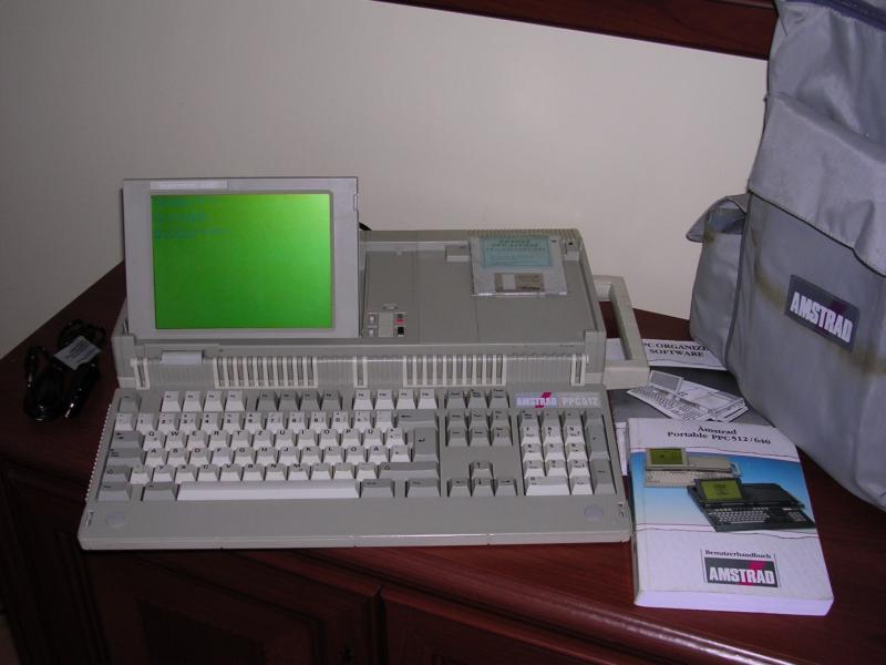
Amstrad PPC512
In 1980s Amstrad made a project called internally AIRO
- "Amstrad IBM Rip Off". In this project they tried to make a cheap IBM
PC XT clone which could be sold in Europe cheaper than IBM units.
Finally they made a complete line of PCs, PC1512 and 1640, with floppy
and hard disk drives, ISA slots and color display. These PC clones
became a success in Europe. To make these PCs
portable without doubling the price, engineers designed Amstrad PPC512 and 640.
Well, it's not the thing we know as "laptop" today. A full-sized 102-key
keyboard opens showing a small LCD (hinged too, MDA or CGA comparible)
without backlight. The computer is equipped with 2 3.5" 720kB floppy
disk drives. It can work from ten 1.5V C-type batteries for hour or two,
from power supply or car lighter adaptor. It could be also powered from
PC1512/1640 monitor. Processor was Nec V30, a 8086 with some more
instructions from 80186 and 8088 emulation mode. PPC512 had 512kB of RAM
while PPC640 had 640kB, internal modem and bi-directional parallel port.
There was no hard drive in it, nor HDD controller. One company in UK
added a small controller and HDD instead of one floppy drive, but it
required soldering to expansion connectors.
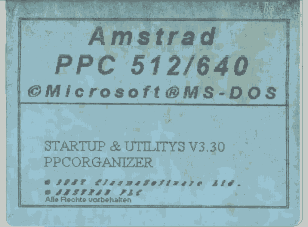
PPC512 was supplied with MS-DOS 3.3 and "Organizer" PIM software. PPC640
had "Mirror II" modem communication program.
| Manufacturer | Amstrad |
|
| Origin | UK | |
| Year of unit | 1988 | |
| Year of introduction | 1987 | |
| Type | Portable, PC | |
| CPU | Nec V30 8MHz | |
| RAM | 512K upgradeable to 640 | |
| Floppy Disk | 2x3.5", 720K | |
| Hard Disk | None | |
| Other media | None | |
| Graphics and display: | MDA/CGA with monochrome non-backlit LCD, external monitor compatible with CGA (320/640x200, max 16 colors) | |
| Sound: | PC Speaker | |
| Keyboard and pointing device: | Full-sized 102-key keyboard with numpad and function keys. | |
|
|
||
| OS: |
MS-DOS 3.3, - External/internal display switch program. - Organizer PIM. |
|
|
Power supply: |
||
|
1 - Ground |
||
| I/O: | - Amstrad
PC512/640 monitor connector - Two expansion bus connectors (unbufferer and unlatched ISA) - 1 serial port - 1 parallel port (unidirectional in PPC512, bidirectional in PPC640) - CGA video out (DB9) |
|
| Possible upgrades: |
- RAM Expansion to 640K - ISA expansion box - Internal modem in PPC640, in 512 empty bay. |
|
| Additional peripherals: | Power supply, car cigarette lighter adapter |
|
It should display standard Amstrad's "Please wait", put some dots and boot DOS from floppy. It should boot from any 720K DOS bootdisk, but if you want to try original disk, download original System disks images. It contains programs for display switch and Organizer too. German system disk set with my PPC was made by "Clasma
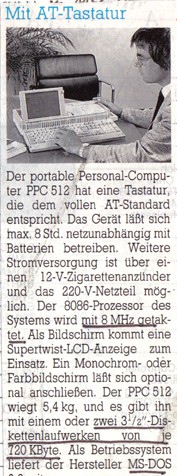
Software" in 1987: Clasma Software (acquired in 1997 by CSI) was indeed involved in PPC software development, as you can read in 1988 article here: "The PPCs, (...) will come with PPC-Organiser, a combined diary, wordprocessor and information card package with additional calculator functions, written by Clasma Software Ltd and published by Triangle Publishing Corp." I don't know history of my unit. It has Spanish markings "Ordenador
Portatil", but has German software disk and manual. Advertisement leaflet - unfortunately in Norwegian, I have no idea what's written there. On the right - excerpt from unknown magazine in German about PPC. There's a mistake about this 8088, PPC uses Nec V30 processor, which is 8088 compatible.. |
 |
| Contents: | Memory upgrade | Expansion box | Pinouts, DIP switches | Links |
To upgrade memory to 640K you need:
- Small soldering iron with sharp tip and soldering alloy
- Something to remove excessive solder (solder sucking pump, absorption
wire etc.)
- 4 RAM chips 41464 (64kBit x 4), -15 or -20.
- 2 RAM chips 4164 (64kbitx1) - -15 or -20
- Sockets for each chip - strongly recommended.
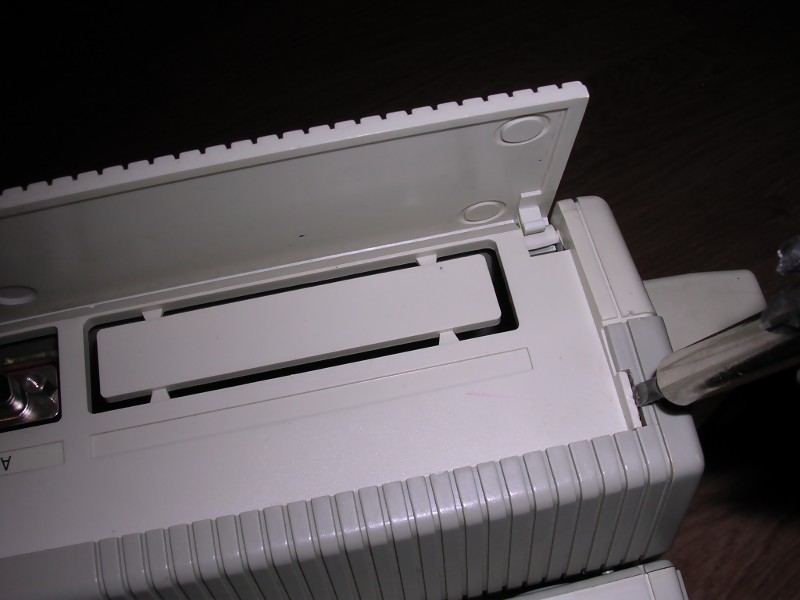
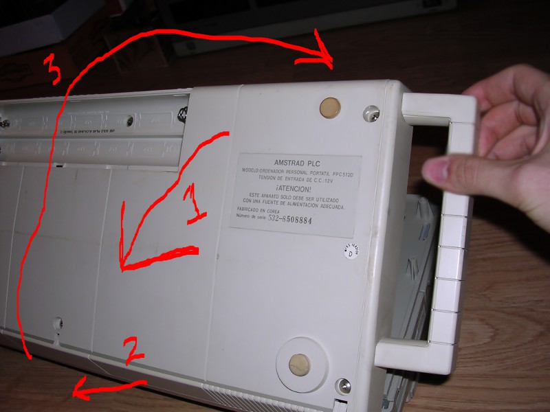
DISASSEMBLY
Do not open keyboard. Flip computer to the bottom and open battery
compartment. Remove 6 big screws. Carefully lift casing prying locks.
CAREFULLY! There are wires everywhere! Look near back connectors, there
will be a big intersection which needs to be unlocked by prying with
screwdriver. As you feel this part of casing free, don't lift it but try
to open it like a book, there are speaker and battery cables going to
this part.
 |
 |
 |
| Prying the last lock | Open towards the connectors, then unlatch, open it back. | Three clips joining PCBs. |
Do not break voltage regulator off the board! (big
3-pin circuit with large metal heatsink)
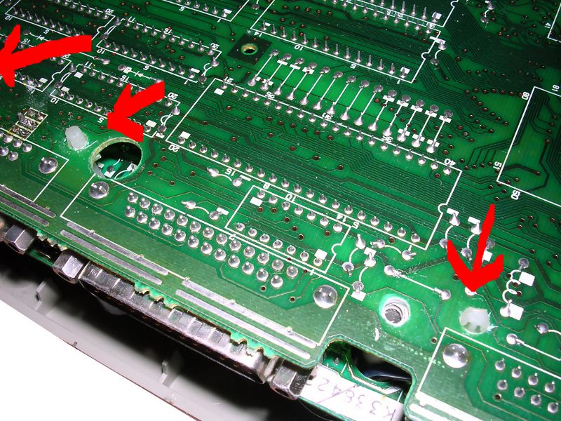
There will be a conglomerate of 2 PCBs, one in another, we need to
disconnect them. Remove screws marked with arrows. Unlock clips by
squeezing them while lifting PCB a bit. Now disconnect a transfer
connector, the connector which joins two PCBs.
We will modify board with memory chips and 6 places for memory chips (soldered
points). This is the LOWER board, you don't need to remove all wires,
just opening it on wires is usually enough if you don't make solder
drops.
You have to remove soldering alloy from these points uncovering holes. Do it by carefully heating one point at time and using solder sucker to remove molten alloy. If you don't have a full hole through board, don't stick soldering iron there but try from the other side. Or just solder it back with some solder and try again - it works too.
Installing first socket: Put it on chips side, with notch facing edge of board, as all other chips. If all pins go through holes, bend few of them on the solder side and solder this socket to PCB. No short-circuits? OK, next one.
Put chips in sockets. Now change 512K-640K link to 640K position on the memory board and another link on CPU board.
Re-assembling procedure is done backwards to disassembly, the only problem you can get is with wires going between halves of transfer PCB connector. You have to patiently push these cables away with a flat screwdriver.
If you removed LCD cable by accident, loosen it's connector screws, put it back, fasten them back.
After re-assembly power it up and check memory count.
Expansion box building plans made by S. Asher were available in http://xaragmata.dyndns-web.com/ppc.html (local)- I haven't built it but it seems logical. The only thing to remember here is to keep wires as short as possible and avoid cable with twisted pairs, as for high-frequency switching signals they are not very good.
RGB Pinout:
|
|
| 1 - GND 2 - GND 3 - Red 4 - Green 5 - Blue 6 - Intensity 7 - Mono video 8 - Horizontal Sync 9 - Vertical Sync |

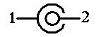
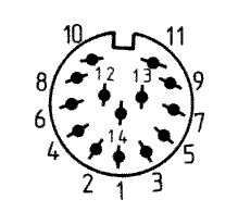
PC512/640 Monitor conenctor:
|
|
| 1 - n.c. 2 - GND 3 - +5V DC 4 - GND 5 - +5V DC 6 - n.c. 7 - n.c. 8 - GND 9 - -12V DC 10 - GND 11 - +12V DC 12 - GND 13 - -5V DC 14 - n.c. |
As you can see, there's no video line connected - only power is used, PC512/640 monitor won't display image from PPC.
DIP Switches:
|
1 - ON - Prefer external monitor, OFF - use LCD 2 - ON - MDA (monochrome) emulation, OFF - CGA 3 - ON turns off LCD that's not seen from programs at all. OFF - LCD is operated with switches 1 and 2. 4, 5 - Display mode seen by BIOS: OFF OFF - External adaptor installed OFF ON - CGA, 40 column ON OFF - CGA, 80 column ON ON - Monochrome If these are not set as 1 and 2 switches, display will stay blank after "Please wait". If external card of given type is installed in expansion box, it'll be used. |
Option links:
Option links are option settings located in mainboard. They look
like a jumpers without jumper soldered in and jumper must be
soldered there.
|
LK1 LK2 LK3 ROS Language OFF OFF OFF English. OFF OFF ON German. OFF ON OFF French. OFF ON ON Spanish. ON OFF OFF Danish. ON OFF ON Swedish. ON ON OFF Italian. ON ON ON Diagnostic Mode. (English) Diagnostic mode makes BIOS look for diagnostic ROM. If it's found, its code is executed. If not, it tests keyboard controller and drives (?) only. LK4 - three pins, left is 512K (closer to memory chips 8 in row), right 640K. It's located on memory board, not CPU board as others. LK5 - Labeled 512K/640K, exact meaning unknown. LK7 LK6 Character set
Codepage |
Links:
http://maben.homeip.net/static/S100/amstrad/systems/PPC%20512/serv1/ppc640_sm_p2.htm
- Service manual (local).
http://www.seasip.info/AmstradXT/ppctech/index.html - Technical
manual
http://web.archive.org/web/20101001100450/http://web.ukonline.co.uk/cliff.lawson/index.htm
- Cliff Lawson's site, good Amstrad-related information.
http://amstrad.cpc.free.fr/amstrad/ppc_e.htm - Photos of internals,
modem and 640 model