ICTester is written in C++/Qt, so it's portable and can be run
both in Windows and Linux environment. All configuration is stored
in 2 files (.ictestrc.ini and .icpower.rc) in .config subdirectory
of user's home directory. It should be compiled on Qt5.x systems
as 4.x is not used since 2016.
Supported
IC list and where to find test sheets
Quick jump:
Error codes
Pin ignoring
Intepreting failed test
results
The first thing you should do after installation or compiling
(ICTester requires Qt libraries and QtSerialPort library, if you
want to build it from sources) is to create your own directory for
test sheets. Test sheets (MOD files) are files which store test
procedures for circuits. You can use test sheets from the original
version of IC Tester's software.
Then it's convenient to add romreader.ini file to this directory,
because it contains all ROM chips definitions. This software can
read ROM chip contents.
To get original test sheet files, you have to download full
installation (MSI) version of Windows software (e.g. from here)
and install it. In Linux you have to install the software with
Wine (use Wine's msiexec) and take Datasheets from their
directory. The original software doesn't work with Wine 1.6.2.
I recommend to create simple directory structure for different
families of circuits (74xx logic, 40xx logic etc.) as it helps a
lot. Then you can put test sheet files in your directory and run
the program.
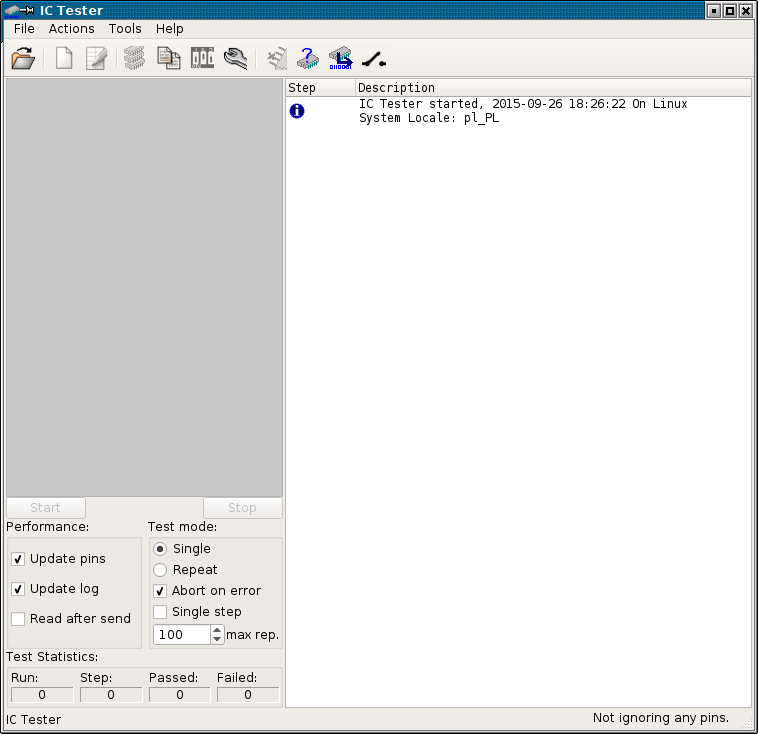
The program's main window (shown below) consists of several parts.
The first thing to do is to load test sheet for verified circuit. To do it, press the first button in toolbar or select item from File menu. File menu keeps list of 10 recently used test sheets. After you click Open icon, Open dialog pops up:
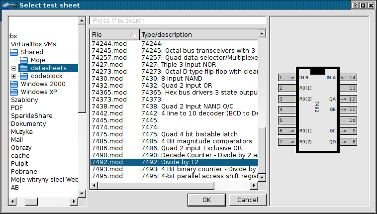
The first thing to do here is to select your test sheets
directory - it will be stored with program's configuration so you
won't have to click through all directories again. Now you can
select test sheet. You can quickly find the sheet by typing part
of its name/description in text box above the list, you can
activate the search box by clicking it or pressing / key. After
you click a sheet, you'll see its preview. Confirm test sheet
selection by clicking OK.
Then you have to configure test parameters, do it by inspecting left-bottom part of main window. The options are explained below:
After you've configured test parameters, you can hit Start button. This doesn't start the test yet. Instead, power requirements window is displayed:
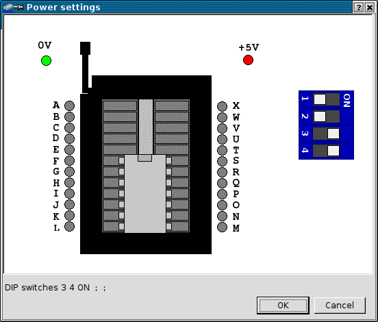
Then you must configure your tester according to drawing and after putting IC in socket hit OK to start the test. Any time you can display current sheet's power configuration by pressing Show Power Requirements button in toolbar.
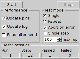
A successful test run is shown below:
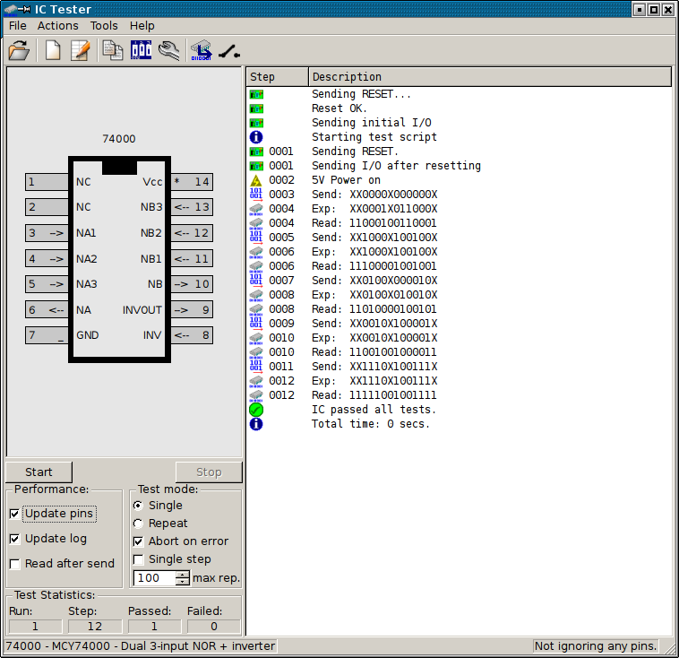
As we can see from log, device (tester) was restarted,
configured, power has been turned on and IC passed all checks.
Notice Test Statistics counters state.
Now let's look at failed test window:
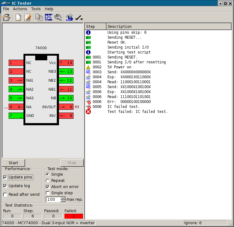
In this picture the test has failed. We can see that:
- Test failed on pins 6 and 9. Error in pin 9
is marked "!!!", which means that it failed the test.
- Error in pin 6 is marked "..." which
means that there was an error, but pin 6 is set as ignored (pin is
marked with "X-").
- Pins marked "*" are power pins.
- Pins marked with "_" are GND pins.
- Pins not marked are NC.
Pin ignoring can be configured
from Actions menu or (since version 20150926) from toolbar button.
You can program some pins (enter them as comma-separated list
after selecting "Ignoring pins") not to be included in test. This
is useful if you have bad IC, but you are using only good pins and
want to verify that they are good in a full test. Ignored pins
list is cleared every IC model loaded or if you leave blank field
in "Ignoring pins" window.
Testing in series (new in version 20190702) can be invoked
from Actions menu or using a toolbar button. This type of test
asks for the power configuration once, performs test and waits for
pressing Return key in the pop-up window. The chip can be replaced
with another one of the same type and pressing Return will test
it. This test will not be interrupted entirely by "Abort on
error" option". To interrupt, press Esc or Cancel in the
pop-up window and the result will be shown on log. This option is
useful when it is needed to test a lot of chips of the same type.
If you get a device error like this:
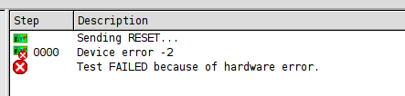
it means that there was a problem. In most cases the problem is:
If your tester hanged with power on, you can always force its reset by clicking the reset icon in a toolbar - the one with opened switch.
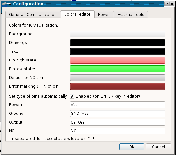
Configuration window can be called from Tools menu or toolbar icon. Let's see the first configuration tab:
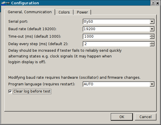
This is quite straightforward. In this window you can change communication
port to which tester is connected. And in most cases only
this setting has to be changed. Modification of baud rate requires
modification of tester itself, so it's safe to leave it at default
19200, change to 57600 if your tester has 57600 jumper installed.
Timeout value 1000 is suitable for most computers. If your
computer is so fast that during long tests tester "drops" some
commands, you can slightly increase Delay every step
value, but this should never happen in modern (>2005) hardware
and in many cases 0 will work.
In this tab you can also point your default language. By default,
the program is started in your operating system's language (or
English if not accessible). This is "AUTO" mode. Using a "Program
language" box you can force specific language to be used for all
next program starts.
You can also disable clearing log before each test.
Sometimes having multiple test results one after another in a
single log may misinform user, but sometimes it may be needed.
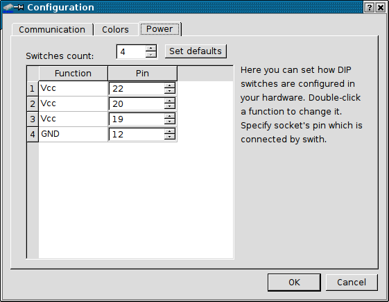
This tab is very important. As you've seen by looking at IC tester hardware, Tester's board has 4 DIP switches connected to power or ground, but it can support more with user settings. For example if you check many chips in 24-pin casings, and they need power connected to pin 24, you can use 5th DIP to connect power to pin 24. This window allows to define these additional switches and they're taken to account when suggesting you power configuration before test. Double-click on a selected DIP switch function to change what is connected to it: Power (Vcc) or ground (GND). There may be "empty" DIP switch too, it's just disconnected so it's only drawn as present, but not used. Then you have to specify socket's pin which is connected with this DIP switch. You can always revert to default setting by pressing Set defaults button.
WARNING! - bad configuration of DIP switches in program
may produce misleading results in power configurations provided by
it. This may cause even damage of tester or IC tested!. It
is important to double-check are settings entered here reflecting
IC tester wiring!
You can build your own test sheet to test new ICs. The test sheet
is a file which consists of two parts:
- IC data: Name, description, pins count,
pins I/O/Power/Ground/NC role and their descriptions,
- IC test script: Information how the
chip should be verified.
First, open any sheet from directory in which you want your new
sheet to be located. This tells the active directory with test
sheets.
Then press the Create new test sheet button in a toolbar.
Program will ask you for new sheet's name and then will go to
editor. You can call editor with any sheet by pressing Edit
current test sheet button.
The editor consists of two tabs. In the first one you specify inputs and outputs of circuit and it should be filled first. Notice that Changing pin number erases the test script so don't make mistake here.
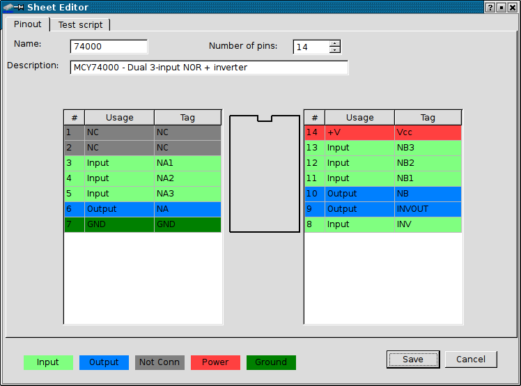
If you change sheet's name, the file name changes too. If you've
changed it, program will ask do you want to preserve file with old
name.
Change pin functions by double-clicking on Usage cell. You
may fill Tag with pin name to make identification easier.
In some operating systems pressing Return will automatically move
editing to the next pin. After specifying IC details you have to
program a test script in the second tab.
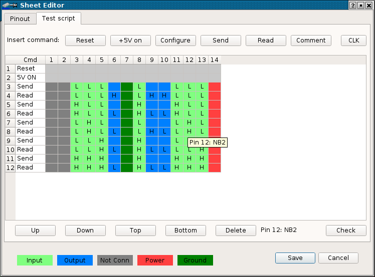
This is a script editor. Usually most scripts start with
Reset-5V ON commands. If your IC has pins which are both
inputs and outputs, you can re-configure I/O during script
execution. High-Low-Doesn't matter (X) states are modified by
double-clicking specified cell. The tag of the pin is shown in a
tooltip near cursor (like in a screenshot) and in the bottom,
between delete and Check buttons to make development faster.
You can generate specific number of pulses (state toggles) on
selected pin using CLK button. Then you are asked which
pin to use and how many toggles do you want. All other pins are
kept in their last state. This is useful in testing counter chips.
Do not put too big values as you may later need to delete them by
hand.
Another important thing is the Comment button (new in
20191028). It inserts comment which can be used to mark important
places in sheet and to describe what particular test does.
However, there are some important information about comments in
these scripts:
1. A typical comment is inert - it is not counted as script's
step, it is not visible during tests. It can be seen and edited
only in sheet editor.
2. If comment text ends with ; - it's not inert anymore. This
comment is part of script now and it's seen that it got a number
in a script. The text of this comment will be shown in log window
during tests. This way you can inform user that e.g. a long
clocking sequence will occur.
3. Comments may not be compatible with original version of
ICTester - this Windows 9x one. It may even remove them from
test sheets edited.
To briefly check some issues you can use "Check" button.
A good testing script should cover the following issues:
This button performs simple checks, and warnings are not
critical, but may be helpful identifying is test complete. These
tests are following:
This checking doesn't modify script nor IC design.
To check are all pins working, the software has a low level test which allows to "light up" a pin in socket. The test window is shown below:
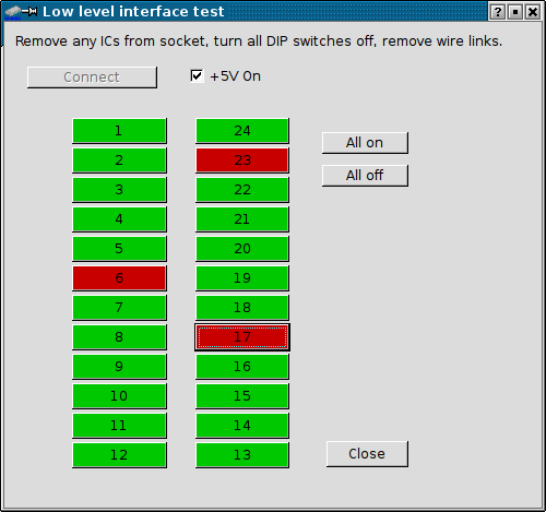
Because PIC's lines use pull-up resistors connected with switchable +5V, it is needed to take it into account during testing with logic probe. To avoid short-circuits, remember to switch all DIP switches OFF and remove any wire links before connecting with device.
To get information about tester firmware, use Identify device
command in Tools menu.
WARNING: This manual is for ROM reading module introduced in
version 20150720. Earlier versions are different
This is the newest version of ROM Dumper which has significant
improvements. First, it doesn't need to be re-built to add a new
chip - user may just write a new chip definition in GUI or text
editor. By programming, only new reading algorithms are added.
Second, this tool now allows to preform advanced read tests of
ROM. This won't test the device's speed, as IC tester is quite
slow, but will certainly test the read stability and access
lines.
The first time you run ROM dumper, You have to select the INI
file with ROM definitions. I recommend placing this file near Your
IC test sheets, as you may need to modify it, e.g. add reading
procedure to ROM you want to read. The file name will be
remembered in main program's INI file, and You will be prompted
for it only when it won't be accessible. Any time, you can change
default INI using "Load INI" button. Newly opened
definitions file will be remembered.
The software consists of 3 tabs. The first one is well known from previous versions and is used to read ROM contents to buffer, save buffer to disk, load it or clear it. You can also verify contents against buffer. The only difference between previous version is that the verification stops if any error has been found instead of completely reading chip, which makes things faster.
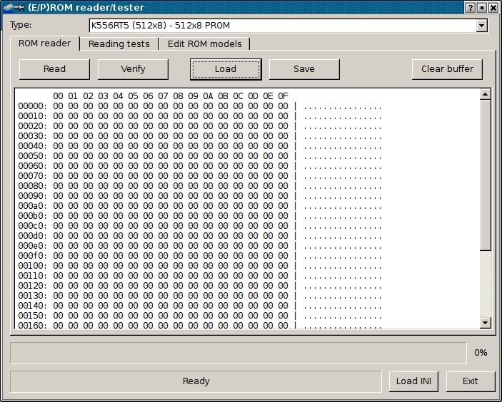
Always the first step is to select the proper circuit from the
drop-down list. For list of supported circuits read this chapter. To read circuit, press Read
button. Program will ask you to set proper power setting and will
read the circuit. The contents will be displayed in buffer in
hexadecimal form.
To verify reading use Verify button. The chip will be read
with comparing with buffer. Also you can use this option to
compare chip with file on disk - just Load the file from
disk and Verify your chip with it. The first different
byte will stop reading and the byte will be displayed in the
status text.
After Reading, you can Save your buffer to disk.
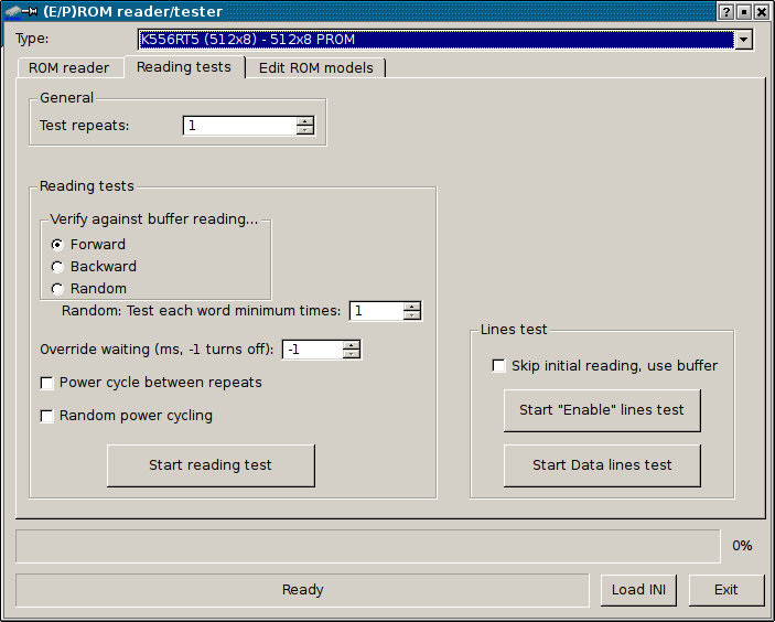
The advanced reading tests are present in the second tab. This
tab is used for advanced validating ROM reading against current
buffer contents, testing data and enable lines. It should not be
used for checking speed, because IC Tester is not very fast as
reader (comparing to devices as fast as e.g. Willem 3.5
programmer). You can set test repeats for all tests here -
if something fails the tests will stop. There are the following
reading modes:
- Read forward - is a normal verification, like the one in
previous tab.
- Read backward - reads ROM contents backwards, evaluating
against buffer.
- Random Read - reads ROM using random addresses.
- Test each word at least ... times - terminates random
read test (or goes to the next repeat) when all words have been
read at least specified number of times.
- Override waiting - allows to override WAIT parameter in
chip definition. -1 turns it off.
ADVANCED DESCRIPTION: WAIT parameters in ROM model
determine how long (in ms) the program should wait between
stuffing the address to chip and reading data, in some chips also
between stuffing the address and enabling chip (some chips need to
be disabled for addressing and then enabled). Default value is 2,
and is good in most cases. Lower values make the chip to be read
faster (which is good for reliability tests), but tester may not
handle commands given so quickly. We usually do not overspeed the
chip as the tester is the bottleneck here.
- Power cycle between repeats - This is advanced thing
which reinitializes chip (turning power off and on) every
specified number of words read, simulating turning power on and
off.
- Random power cycling - Randomly turns power off and on.
Some old chips, especially soviet PROMs in brown cases like to
fail right after powering up. This test should reveal problems.
For NORMAL reading algorithm, there are also two additional
tests. Both tests require at least one chip reading and this
initial reading can be skipped by using checkbox below (buffer
contents are used). Both of these tests are not conclusive, e.g.
they don't indicate always that the chip is bad and their results
must be analysed with knowledge about chip and its usage.
Data lines test - First, the chip is read to buffer (or
buffer is used). Then all words are checked if all bits change. If
bits are "locked" in 1 or 0, it is indicated. Unused lines in
chips may be just not programmed, or line may be bad.
"Enable" lines test - The chip is read to buffer or buffer
contents are used. Then one of ENABLE pins is toggled to the
opposite state and chip is verified. If the result is different,
the pin "passed" the test. If the reading is the same, pin is
taken as "constant". This operation is performed for every pin
defined as "ENABLE" or control pin. It may indicate damaged ENABLE
lines, but in many PROMs there are lines, e.g. for programming,
which should be kept e.g. high, but it is not compulsory. This pin
will be indicated in the end of tests with a good chip.
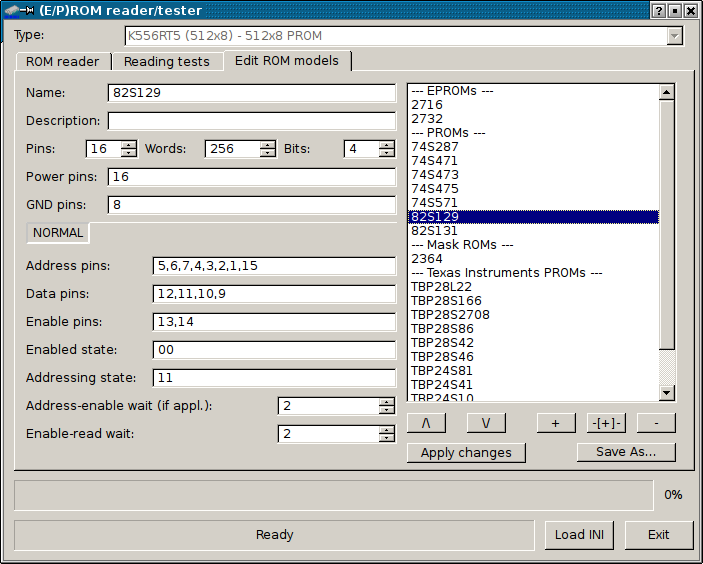
The third tab is a model editor. It allows user to modify or add
ROM chip definitions to INI file. After applying ("Apply
changes" button) modifications, modified version is used,
but to be re-used after closing ROM dumper window, it must be
saved ("Save As..." button) to INI file.
Right side is quite obvious, allows to add, remove and order
items. It is possible to add model ("+" button) or
"delimiter" ("-[+]-" button), which has name always
starting with a dash. If there is no dash in comment's name,
program will add one when applying. These delimiters are used to
split ROM listings to nice sections for better navigation.
Remember to apply Your changes after changing model settings in
the editor.
Currently only a typical address-data algorithm called NORMAL is
implemented, so this "NORMAL" is just indicating it.
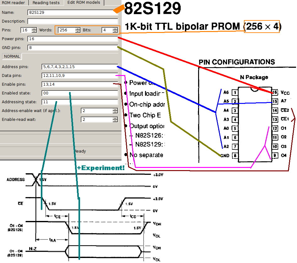
The picture below shows how the definition is made from
datasheet. Then new definition should be verified experimentally,
especially enable/addressing states, which in some chips are not
needed:
WARNING!
This is a highly experimental tool which may even damage
tester or IC identified. This tester cannot detect Hi-Z
(high impedance) state, so testing is made around test sheets.
Although quite safe, some fragile ICs may not survive momentary
current draw. Use it carefully and as fast as possible. Generally,
if a chip is easy to damage with TTL pulser, don't use it in
identification.
To skip warning on start, use any text editor to open Your
~/.config/.ictestrc.ini (Linux) or ictestrc.ini (Windows) and add
warnUnstable=0
at the end of [Test] section.
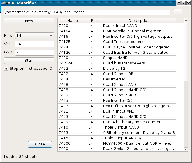
The tool can be launched from menu or toolbar button. This tool
is made to help identify chips with worn off markings. On first
start-up, you have to specify a directory with test sheets. This
directory is recursively searched for test sheets to test and a
list is shown in right-side table. You can always change it using
"..." button. The "New" button reloads sheets and
makes program ready for another detection.
First, it is needed to input pin number and their power
requirements. It can be easily deduced from PCB how the chip is
powered up. When you select pin number, the list is filtered again
and default (for 90% of 74xx circuits) power settings are entered
automatically.
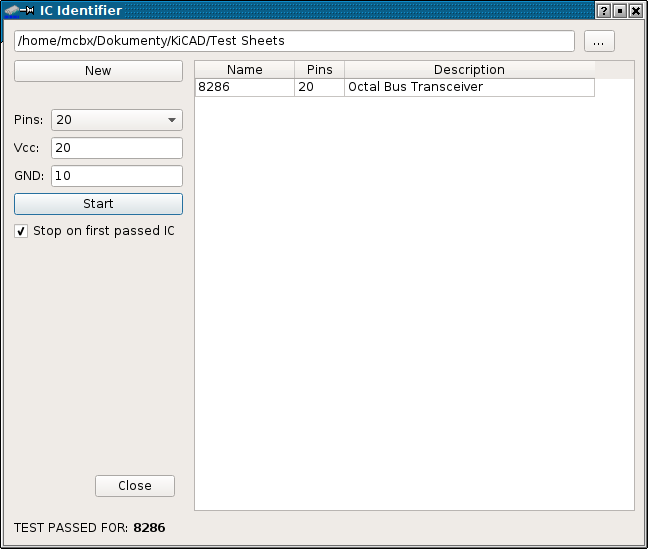
After entering power pins (in comma-separated list, remember that
/CE and /OE pins, sometimes connected to ground, are functional
pins, not GND) and clicking Start two things happen:
1. List is filtered again, to make list of chips with power
according to specification. If no chips are left after this
filtering, the program stops here and displays message.
2. If there are chips with correct number of pins and power
specification, program asks user to prepare tester, then chip is
tested against all items in the list. You can see the testing in
status bar and by blinking power LED in tester.
By default, when test passes, identification program stops and
type of passed IC is shown in the status bar. You can force test
of all IC definitions by unchecking "Stop on first passed IC"
checkbox.
Below you can see the program after successful 8286
identification.
GUI program can be started with following command-line parameters:
There is a command-line tool which has basic tests and diagnostic
capabilities. The usage is following:
ictestcon ttySx x circuit.mod
Where:
Available commands:
- ictestrc.ini is quite self-explanatory, the only
thing is with colors - they're stored separately, Red-Green-Blue,
value after value.
- icpower.rc consists of set of lines, each line has
3 comma-separated values. The first value is DIP switch number.
Second - to which is connected (0 - ground, 1 - power, 2 -
nothing), third - DIP socket pin which is connected to the other
side of switch.
WARNING: From version 20190702 these files reside in
~/.config, not in ~ as previously. The program, both command-line
and GUI, will copy the files to new locations and use these but
will not delete the original files in case you want to use
an older version. It is up to the user to decide should old files
be kept (when older version of program is used in parallel) or
not.
TEST SHEET (MOD FILE) FORMAT:
The format is the same as in original EPE IC tester. CR/LF (line
endings) are the same in Linux version, Windows-like.
If a line starts with # - it's a comment. Skipped during read.
Empty lines are skipped too.
After ignoring comments and blank lines, we have a pure script
file.
Now it's needed to parse it, each line has its meaning, line order
is significant here.
1. IC Model name (e.g.. 7404)
2. IC description (e.g.. Quad NAND gate)
3. Number of pins in package (called later NumOfPins)
4. Pin for + power .
5. Pin for GND - if there are more GND/power pins original
software gets lost, my software proposes wire-based solution.
Starting from line 6 there are NumOfPins lines for each pin, they
look like: a,b,c: (3 fields comma separated):
- a - Pin number.
- b - Pin description as string
- c - pin usage
- 0 - Logic i/p
- 1 - Logic o/p
- 2 - Universal i/o reconfigurable later? - not
fully implemented.
- 3 - GND
- 4 - Vcc
- 5 - NC
Then test script lines come until end of file, they look
like a,bcdefghijklmnopqrstuvwxyz
- a - line number
- b - command
- 0 - Reset device (Vcc off)
- 1 - Vcc on
- 2 - Configure pins.
This
operation is usually not present in start of script, but generated
from pin configuration.
- 3 - Send state to pins - zero should be sent
to o/p pins.
- 4 - Read state from pins
- c..z - directive arguments:
- 0 - logic 0 , or input in command 2
- 1 - logic 1 , or output in command 2
- X - logic "doesn't matter" in testing or
power pins in setup
ROM READER (INI) FILE FORMAT
The file is in fact Windows-like INI file containing
serially-written ROM definitions. All pins are relatively to the
chip, not socket, e.g. 14-pin chip's pin 7 is socket's pin 12, but
it is described as just pin 7. In the top there is always a
GENERAL section which looks like:
[GENERAL]
MODIFIED=20150709021935
It contains last save date, in YYYYMMDDhhmmss format.
Next, ROM definitions are written one after other. There must
be always at least one empty line between definitions.
If there is an empty section starting with "-" like:
[--- EPROMs ---]
It means that is it is a category. The categories are for better
ordering chip models and are not selectable.
Normal chip model looks like this:
[2716]
DESCRIPTION=EPROM, also K573RF2
PINS=24
GROUND=12
POWER=24
BITS=8
WORDS=2048
METHOD=NORMAL
ADDRESS=8,7,6,5,4,3,2,1,23,22,19
DATA=9,10,11,13,14,15,16,17
ENABLE_PINS=18,20,21
ENABLE_ON=001
ENABLE_OFF=011
WAIT_ENABLE=2
WAIT_READ=2
The section header (always in square brackets) contains chip
name. Next variables are:
NORMAL method has the following parameters:
After each definition at least one blank line must be
present.
The ROM dump tool can read he same ROMs that GUI, using INI files
as definition sources.
The usage is:
icromread FILE.INI [r/s/d] port model FILE.BIN
Where:
FILE.INI - is a path to INI file with ROM definitions.
[r/s/d] is parameter:
r - reads ROM content to file,
s - as above, but doesn't prompt for power
requirements,
d - displays only contents of INI file. Doesn't
need port/model/file parameters,
v - verifies ROM contents against FILE,
f - as above, but doesn't prompt for power
requirements.
port - is a serial port for tester. It can be separated with : and
baud rate can be given (e.g. /dev/ttyS0:57600), if not, 19200 is
used.
FILE.BIN is the ROM dump file to write to or compare with.
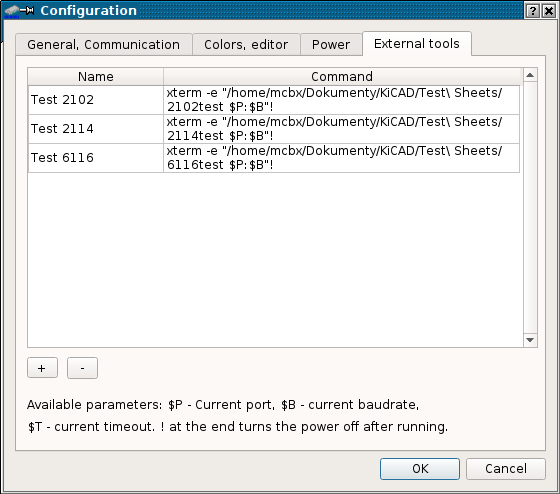
The following S-RAM test programs are enclosed: 2114test,
2102test, 6810test, 6116test and 93415test, for testing specified
S-RAM chips. Running of them is simple:
| Name |
Alternatives |
Comment |
| EPROMs |
||
| 2716 |
K573RF2 |
Some chips won't give reliable results |
| 2732 |
||
| 2532 |
TI EPROM, also C21008 Mask ROM |
|
| Generic PROMs |
||
| 74S287 |
TM621?, 82S129 | |
| 74S471 |
74S470, TM622 |
|
| 74S473 |
74S472 |
Not tested |
| 74S475 |
74S474 |
Not tested |
| 74S571 |
||
| 82S129 |
as 74S287, a bit different algorithm. |
|
| 82S131 |
||
| 82S141 |
||
| 87S185 |
||
| Mask ROMs |
||
| ZCM38818 |
2364 |
Mask ROM |
| TI PROMs |
||
| TBP28L22 |
28S22, 28LA22 |
|
| TBP28S166 |
28L166 |
Not tested |
| TBP28S2708 |
Not tested | |
| TBP28S86 |
28L86 |
Not tested |
| TBP28S42 |
28L42 |
Not tested |
| TBP28S46 |
28L46, TM624 |
|
| TBP24S81 |
Not tested | |
| TBP24S41 |
Not tested | |
| TBP24S10 |
Not tested | |
| TBP18S030 |
||
| Monolithic Memories
PROMs |
||
| 6309 |
5309, 6308, 5308 |
|
| 6330 |
6331, 5331, 5330 |
Not tested |
| 6300 |
6301, 5301, 5300 |
Not tested |
| 6305 |
6306, 5305, 5306 |
Not tested |
| 6352 |
6353, 5352, 5353 |
Not tested |
| 6388 |
6389, 5388, 5389 |
Not tested |
| 6348 |
6349, 5348, 5349 |
Not tested |
| 6336 |
Not tested | |
| 6340 |
6341, 5340, 5341 |
Not tested |
| 6380 |
6381, 5381, 5380 |
Not tested |
| Soviet PROMs |
||
| K556RT5 | KP556RT5 | |
MCbx, 2014,15-19.