Home 

IBM 5150/5155/5160  -  Minimum Diagnostic Configuration


NOTE:   This procedure was written specifically for IBM 5150/5155/5160's.
For clones, applicability/suitability will depend on how close the clone is of the IBM 5150/5155/5160 (including BIOS).
For clones, references here to specific capacitors (e.g. 'C56') will definately not apply.


You are here because your IBM 5150 or IBM 5155 or IBM 5160 appears to be 'dead'.  The fan in the power supply might be turning, or perhaps only briefly turned at power on.  You may have even heard a small click from the speaker at power on.  But apart from that, your 5150/5155/5160 appears to be 'dead'.

At this time, it is good to see if the 'minimum diagnostic configuration' is working.  Per the photo below, for a 5150/5155/5160, that configuration is:
* Motherboard, with switches 5 and 6 on SW1 both set to off
* Power supply
* Speaker

minimum_diag_config.jpg

In the photo above, those three items have been removed from the computer, but you don't need to do that.

Note that there are no cards plugged into the motherboard.  That is very important for this test.
Note that there is no keyboard plugged into the motherboard.  That is very important for this test.

Note that the motherboard is the only device connected to the power supply.  That is very important for this test.

minimum_diag_p8p9.jpg When attaching the 2 plugs (P8 and P9) from the power supply to the motherboard, ensure that you do that correctly, because it is possible (with force) to attach them to the wrong receptacles (i.e.  P8/P9 swapped).

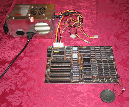
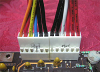
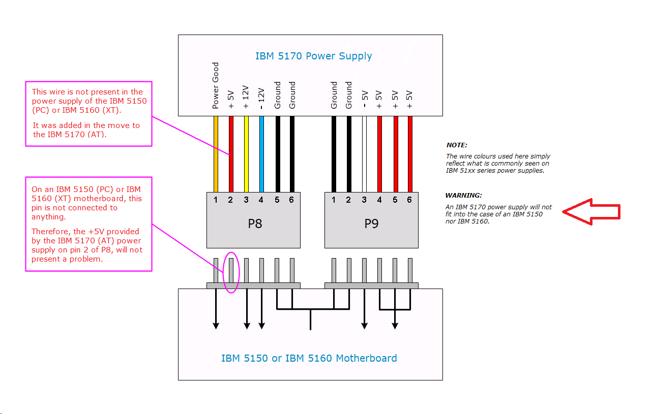
Do not worry if your P8 is missing the red wire (next to the orange wire) shown in the photo.  My power supply (a non-IBM one) has that wire because it's designed for ATs (as well as PCs and XTs).  More information on that is here

Note too, that non-IBM power supplies may use wire colours that are different to those shown here.

minimum_diag_sw1.jpg As specified earlier, on the motherboard, switches 5 and 6 on SW1 are both to be set to the OFF position (monochrome card).  For this procedure, that is very important.
Actually, either 5 or 6 can be ON, but not both.  For simplicity, I'm saying to set both 5 and 6 to OFF (per the switch photo).

On a 5150 motherboard, there are 2 switch blocks: SW1 and SW2.  SW1 is the one closest to the center of the motherboard.

Your SW1 switch block may contain different looking switches.  If so, refer to here if you are unsure about what is on and what is off.

minimum_diag_speaker.jpg When connecting the speaker, the speaker's two wires need to go to the outer two pins of the 51xx motherboard's 4-pin speaker connector.

Polarity is not important here; it does not matter which wire goes to which outer pin.   (reason)

(Some clone motherboards may use different pins, or may even use a different connector.)


Doing the Test

So with the equipment configured as above, turn on the power supply.  After about 5 seconds, expect to hear a series of beeps (1 long, then 2 short) from the speaker.

Click here if you heard the beeps.

Click here if you did not hear the beeps.

Click here if you heard one long continous tone (never stops).