| Parent |
| Symptom: | I have just finished constructing an AT2XTKB, but it is not working. |
| Fix: | Some (i.e. not all) possible causes: • Not wired/constructed per the circuit diagram. • Bad soldering. • The 12F629 PIC chip was not programmed with the AT2XTKB's firmware. • The OSCCAL value was lost/overwritten when programming the 12F629 PIC chip - see here. • The AT-class keyboard that you are using is faulty. • The particular model of AT-class keyboard that you are using is incompatible with the AT2XTKB. • DIN cable between AT2XTKB and motherboard - incorrect type for AT2XTKB use. • DIN cable between AT2XTKB and motherboard - correct type but faulty. • DIN cable from motherboard plugged into wrong connector on AT2XTKB. • IBM 5150 (IBM PC) - AT2XTKB is connected to motherboard's cassette port instead of keyboard port. • The AT2XTKB is working; it is the motherboard's keyboard interface circuitry that is faulty. |
| Symptom: | Works with some AT-class keyboards, but not others. |
| Fix: | Member schnurzel of the Vintage Computer Federation Forums modified the AT2XTKB's version 0.94 firmware. A link to schnurzel introducing the firmware is at here. Try that firmware, known as 'RT01'. |
| Comment: | May not work fully with some keyboards. For example, on a Compaq KB-0133 keyboard, the the NUM LOCK, CAPS LOCK, SCROLL LOCK lights do not work. |
| Symptom: | I need the 'Scancode E0 pass-through' functionality, but it is not working. |
| Fix: | Step 1: Ensure that you have pullup resistor R3 in place. Step 2: Ensure that jumper JP1 is off. Step 3: Ensure that the version of firmware in the 12F629 PIC chip is at least version 0.93 |
| Comment: | Functionality rarely required. See post #203 at here for an example. |
| Symptom: | The F7 key is not working. |
| Fix: | Upgrade the 12F629 PIC chip's firmware to version 0.94 |
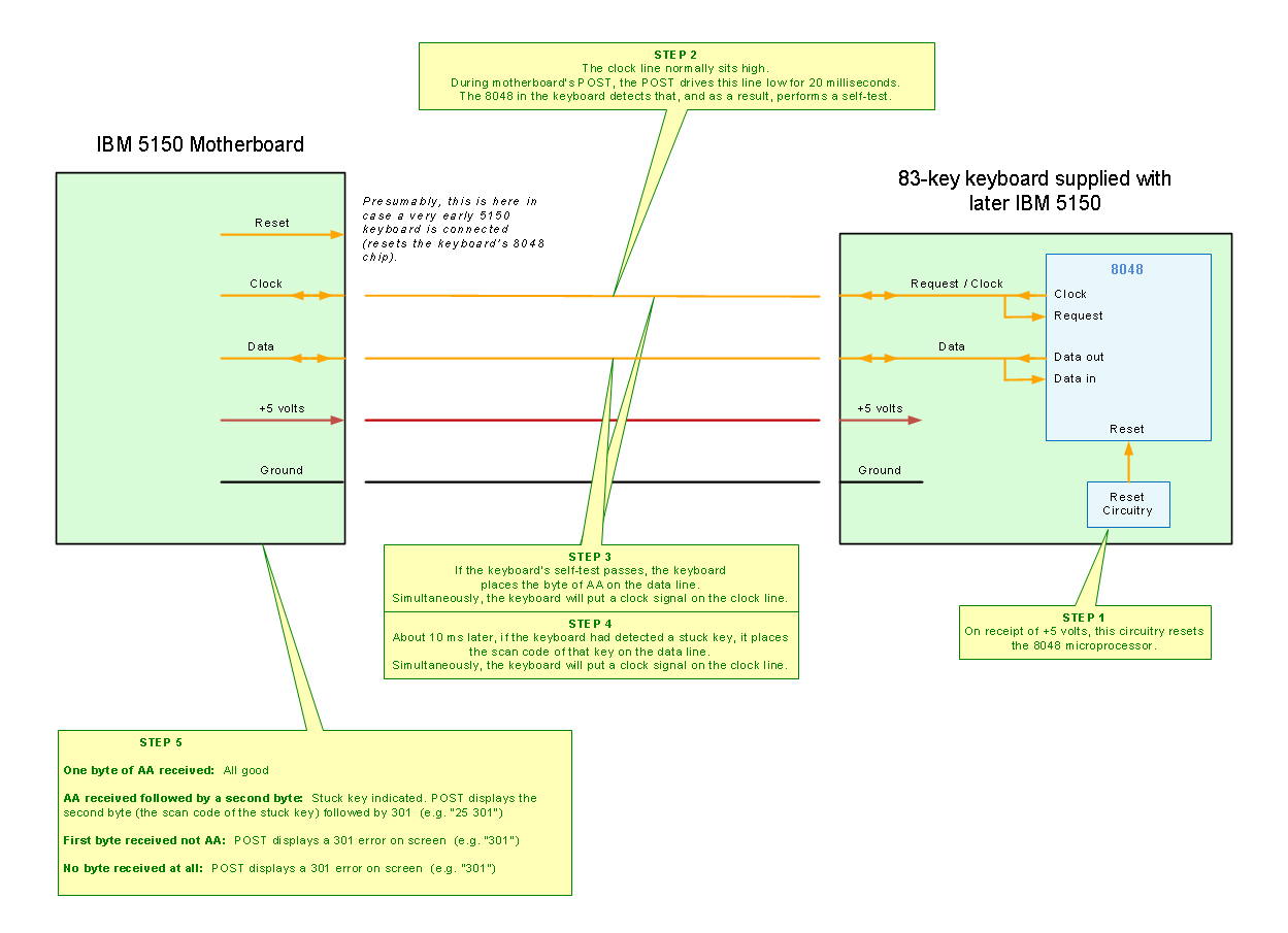
| Background: | On an IBM 5150 or IBM 5160, the motherboard's POST will display a 301 error if no (XT-class) keyboard is plugged into the motherboard. |
| Observation: | It will be observed that if an AT2XTKB is plugged into an IBM 5150 or IBM 5160, and the AT2XTKB has no keyboard attached to it, the expected 301 error will not be displayed. |
| Answer: | Refer to the diagram at here. When the AT2XTKB sees the clock line go low, it will respond with an AA byte to the motherboard, making the motherboard believe that a keyboard is present. |