IBM EGA Card  -  Switch Settings


The IBM Enhanced Graphics Adapter (EGA) is primarily designed to connect to IBM's 5154 monitor (CGA and EGA).

If reconfigured via the red switch block, the card is capable of use (at reduced functionality) with the IBM 5151 monitor (MDA) or the IBM 5153 monitor (CGA).

Make all IBM EGA card switch changes when the computer is powered off.


Notes regarding reconfiguration for 5153 monitor (CGA) or 5151 monitor (MDA)

1. With such reconfiguration, the IBM EGA card is not 'pretending' to be a CGA card nor an MDA card.  It remains being an EGA card, one that the card's BIOS knows via the switches, what it can and cannot output to the attached monitor.

2. Do not change the video configuration of the IBM motherboard.  Leave it set for whatever the required setting is for an EGA card.

3. There is reduced functionality.  You are not getting full EGA capability on these old monitors.  For example, with an IBM EGA card and 5153 monitor combination, there is no video mode of 10h (a video mode used by a lot of EGA games), and in text modes, you will still see 'chunky' 8x8 characters.  Refer to the table at here to see what you get and don't get.

4. The card changes the functionality of some pins in the 9-pin monitor connector.  See here.

5. In some cases, you may discover that the setting of jumper P1 may need to be changed to the '2 & 3' setting.  See here.


Switch settings

Below is pictured the most common settings of the switch block.  Additional settings are contained in the document at here.


ibm_ega_with_ega_monitor.jpg 
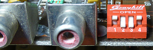
IBM 5154 monitor (EGA),
or compatible, connected.
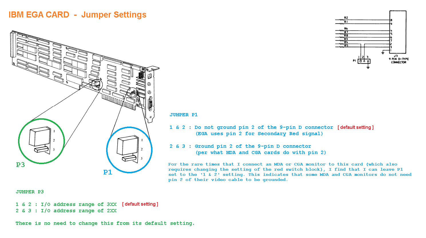
Make sure that jumper P1 is in the 1-2 setting.
ibm_ega_with_cga_monitor.jpg 
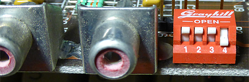
IBM 5153 monitor (CGA),
or compatible, connected.
1. Results in the functionality of pins in the 9-pin connector being changed to suit the 5153.

2. Results in BIOS video modes being restricted to suit the 5153.
ibm_ega_with_mda_monitor.jpg 
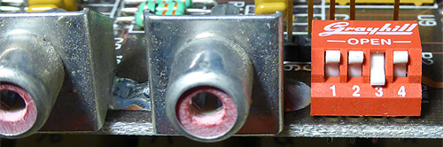
IBM 5151 monitor (MDA),
or compatible, connected.
1. Results in the functionality of pins in the 9-pin connector being changed to suit the 5151.

2. Results in BIOS video modes being restricted to suit the 5151.