1 - Output 1
2,4 - GND
3 - Output 2
5 - +9-12V DC (internally regulated to 5V)
Transled driver reverse engineering using
logic analyzer
(step-by-step version)
About a year ago I got an unusual keyboard with TRANSLED label on it. Not much is known about it - only that Transled company was in Cracow, they have a web page (Under Construction since 1998). Looking inside and peeking on internet auctions revealed that Transled manufactured LED advertisement displays. You can see it on its page in the computers section. After cleaning it, removing leaking battery, dumping ROM and trying to get some data from inside, I gave up and abandoned reverse engineering of it using 0,5-1MHz TFLA analyzer hardware.
Recently I bought some cheap 24MHz Logic Analyser, so I decided to test it by reverse engineering the driver.
The Transled system seems to be quite simple:
__________
________________
| |------------|LED
DISPLAY UNIT|
| Driver |\
|----------------|
|__________| \ /
Power supply
First, let's look on the DIN socket pinout revealed by opening the Transled driver:
1 - Output 1
2,4 - GND
3 - Output 2
5 - +9-12V DC (internally regulated to 5V)
|
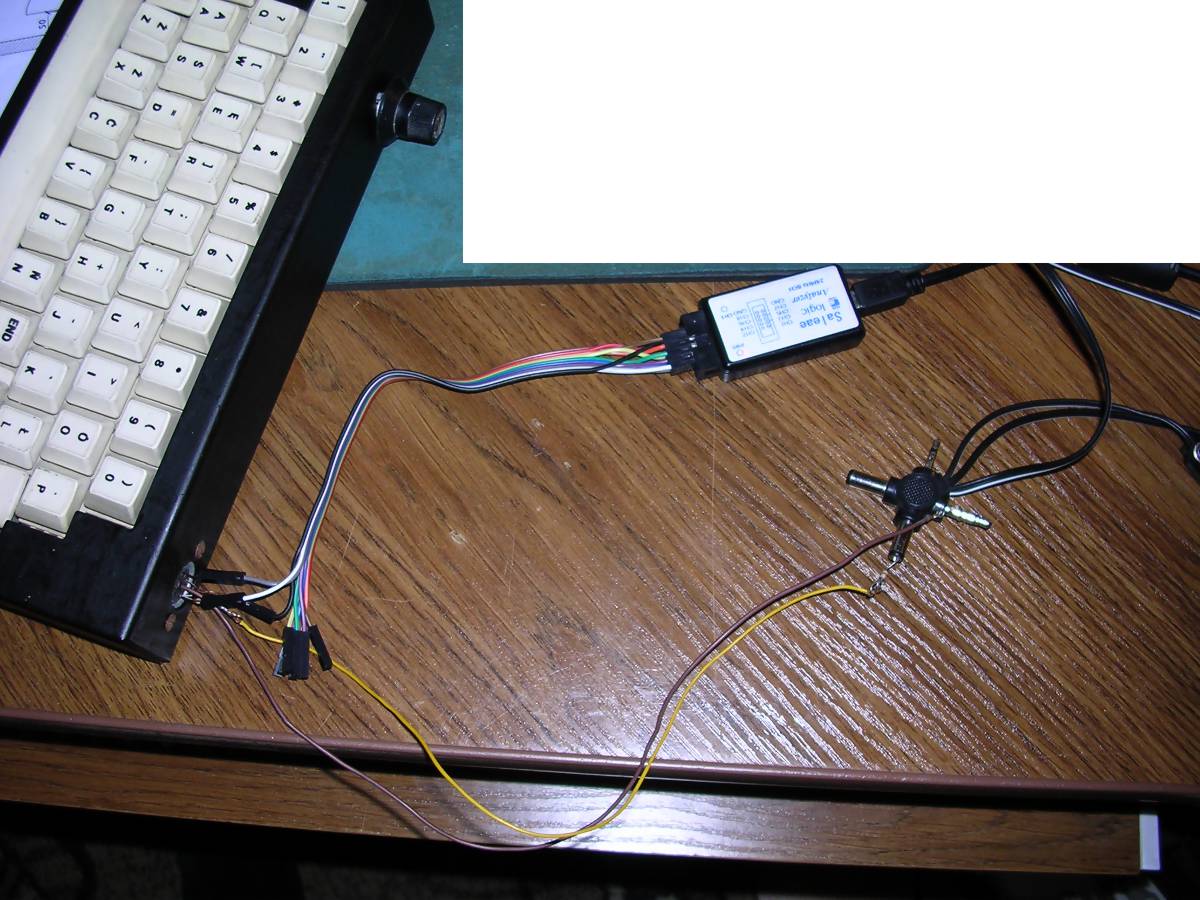
So, I can imagine that one Ground and two outputs were used to drive the LED display, probably some power was supplied directly to LED unit as few dozens of LEDs can't operate on logic levels. The main unit was powered using 12V power supply, 12V is internally regulated to 5V. First, I have connected the analyzer to driver. Only 5 wires
were needed: A whole alignment can be seen in the picture on the right. I've turned the trimmer to the slowest position and started the capture. I got quite good effects on 8MHz but I used 12MHz. |
 |
 |
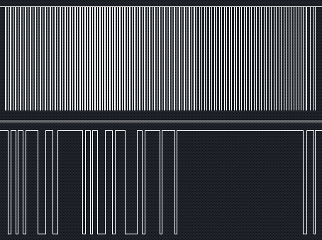
Well, I can see repeating bursts of signals, nothing
more. Now a comparison between two edge positions of trimmer. The trimmer regulates the "frame rate" or "refreshing" of display. As you can see, the signal is made of series of bursts of data in more or less constant interval (set by trimmer). Let's look at the burst itself:
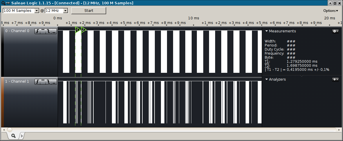
We can see that channel 0 (connected to DIN pin 3) recorded a series of pulses while the channel 1 (connected to DIN pin 1) got only few changes. It means that: Pin 3 is a clock of serial transmission made on pin 1 After measurement, it was discovered that the clock goes low (active) for about 0.33us in 3.166us intervals, giving ca. 3.5us for one bit transmitted. This is roughly 280kBit/s. Quite fast as for old Z80 system, but it means that the data goes almost directly to LEDs. Now let's look at the end of the pulse. Notice the strange behavior of clock at the end of the burst. We should examine it better. |
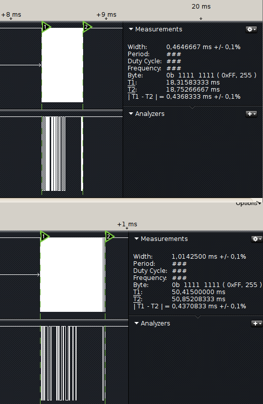
Let's look at the end of the burst:
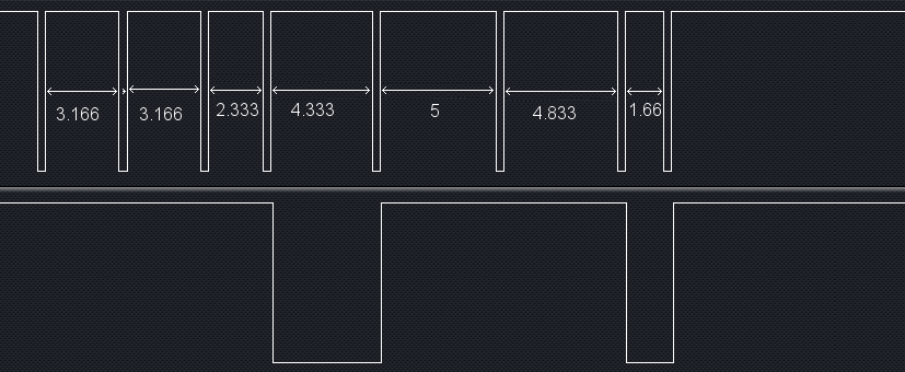
After few normal 3.166us bits, we have an unusial 2.333us interval, then
4.333us, 5us, 4.83us, and a very short 1.66us. CPU must be doing something in
the end, something different than transmitting bits. Maybe it needs additional
memory access for 4.4, 5 and 4.83 bits, and the last one is some way computed?
These time differences are usually ignored by 74... logic chips, but for reverse
engineering they have meaning. Generally, it means that...
The last bits of the burst have different meaning than other ones.
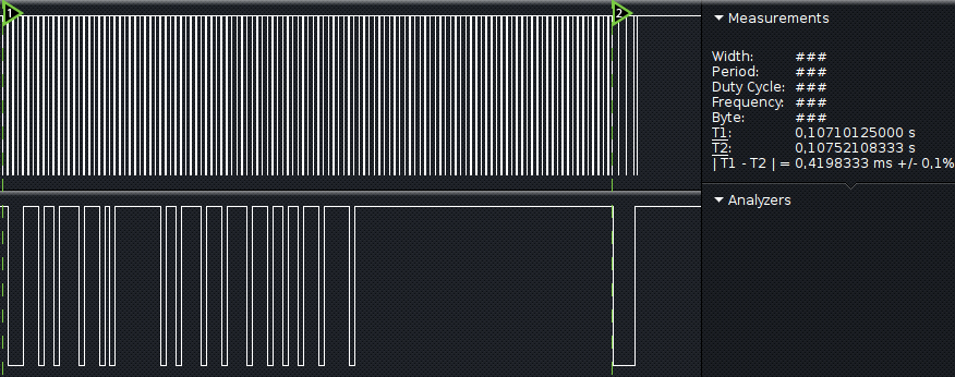
Let's cut the last "nice" bits and look at time:
|
We have 420us/3.5us for a bit means that: The burst consists of 120 bits of "regular" data, then 4-bit "tail" of additional data. OK, we're ready to look to the photo I've stolen from one internet auction. I don't remember which one, I used Google cache: This photo is poor quality, but we can count about 120 LEDs in horizontal axis and 8 in vertical. So let's carefully assume: The 120 bits are bits of one display's line. Let's look at the "tails" of 9 bursts: |
|
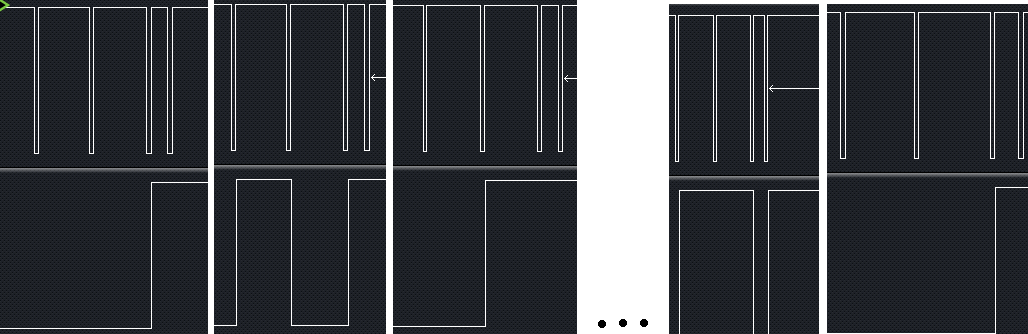
So, every 8 bursts, the tail parts repeat. This is pointing us
that it may transmit picture frames line by line. We can see that the first bit
is always 0. So we have 3 bits. Let's read them from right to left, taking low
as 0 and high as 1:
100
101
110
...
011
100
So it means that:
The last 3 bits are binary counting picture lines
Now we know how the LED module works:
1. Loads 120 bits to some shift register.
2. At 121th clock tick it switches input to line register.
3. Next 3 bits are used to multiplex data to correct line. Then, maybe after a
time, it is latched.
4. Awaits next chunk.
Let's start to program.
Part 2: Programming time
Logic analyser software allows to output data in CSV or TSV
(Tab-separated) format. The format is optimized, i.e. not all samples are
written, but only samples in which change has been monitored, with absolute time
in seconds. The program, written in Perl, can be downloaded with examples in the
bottom of this page.
The first thing made by program is to determine time step between each step in
file:
chomp $row;
my @record=split('\t',$row);
$deltaTime=($record[0]-$prevTime)*1000;
if ($intoChunk==0)
{
#check are we starting a chunk?
if ($deltaTime>0.1)
{
$intoChunk=1;
$bitCount=0;
}
}
...
$prevTime = $record[0];
A row is splitted to parts, then time difference in milliseconds is calculated. If nothing happens for more than 0.1ms, it means that a new chunk will start. Then...
if($record[1]==0) #Clock goes active - bit is
transmitted
{
if ($bitCount<=120) #First 120 bits - displayed data
{
$line=$line.$record[2];
}
elsif ($bitCount<122) #Always one-zero
{
}
elsif ($bitCount<125) #line address
{
my $no = $bitCount-121;
$addr=$addr.$record[2];
}
$bitCount++;
When we loaded 124 bits of data, it is needed to form a line (I know I should use regexp, I was just lazy with these bits):
if
($bitCount==125)
{
$intoChunk=0; #line finished
$addr=reverse($addr);
$addr=oct("0b".$addr);
$addr=-1*($addr-7); #line number
$lines[$addr]=$line; #add line to
array
$lineCount++; #increment line count
$line="";
$addr="";
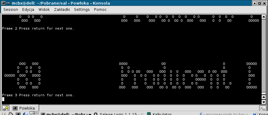
If we've loaded 8 lines - let's display them. Remember about inversion - lit LED is represented as LOW, so ones have been replaced by spaces. It looks nice in a console:
if ($lineCount==7) #if we have a frame, let's present it to user
{
$lineCount=0;
$fr++;
foreach my $l
(@lines)
{
$l =~ tr/1/ /;
print $l,"\n";
}
print "Frame
",$fr," Press return for next one.\n";
<STDIN>;
}
}
}
The result is:
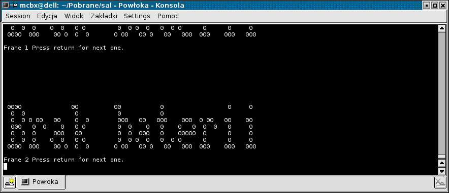
Scrolling (notice earlier frame in the top of console window):
Downloads:
7-zip archive containing the Perl script and two example TSV dump files, which can be read by script.
MCbx, 2015