[令和二年五月十八日/2020年5月18日]
KEYENCE NR-350データ収集器/PCオシロを、購入

昔から、アナログ式メモリ・スコープやデジタル型オシロには憧れを持っていて、機会があれば買って、使ってみたいものだと思っていた。
帯域幅1〜2MHz位の狭いものなら、安価で入手出来るのだが、以前に下手な買い物をしたことがあって、懲りてもいた。
(アナログ・デジタル信号が記録出来る)帯域幅100MHzくらいのものは、とても高価なので、ずっと横目で眺め、パスしているだけだった。
今回偶々、安価なジャンクのデジタル・オシロを修理するという「YouTube」動画を拝見して、面白そうだと思った。
しかし、どうも図体が大き過ぎで、置き場所が確保出来そうにないなどの問題で、これも止めた。
ところが、偶々、コンパクトそうなKEYENCE製データ収集器NR-350(100MHz?)というのを見付けたので、(高いが渋々!)買ってみた。(¥11,435送料込み)
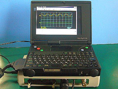
これは、本来は「データ収集器」という名目だが、高速のサンプリングが出来るので、一種の“遅延・記録型オシロ”として使えるはず。(図2<クリック>)
だから、単発現象の観察などにはもってこい!だろう。
これは、Win95/98で使用可能だから、「PC110」ででも使えるのではないか?もし可能なら、(休業中の)「PC110」の有効活用にもなる!と考えた。
でも、この値段は甚だ微妙で、Win95、Win98で使うような"骨董品的・面白半分的計測器”なのに一万円以上もした。(尤も、ここに、それを“買う阿呆”も居たわけだが。苦笑)
まぁ、シナ製の周波数帯域の狭いデジタル・オシロでも結構な値段なので、これ位は我慢しなければいけないのかも?
問題は、周波数帯域で、100MHzサンプリングだったら、有効帯域幅は、それの1/10位だろうから、「PC110」のクロック33〜40MHzに対応するには、ちょいと狭い。簡単なテストでは、やはり少し苦しかった!(図1)
もう少し使ってみて、使い物になるかどうか、調べてみる。
−−−−−−−−−−−−−−−−−−−−−−−−−

+++ 補助部品が大き過ぎる! +++
電源を入れてみようとし、「ACアダプタ」を横向きのコンセットに差し込んでみたら、即座に自重で抜け落ちてしまった。ドスン!
"12V、1.1A”ならジャンク箱に掃いて捨てるほど...無かった!プラグが、そのまま差せるアダプタは、運悪く、無かった!
止む無く、小型の「ACアダプタ」で、それのプラグ部だけを作り替えて、それを使うことにした。(図3)
その他、「PCカード・ケーブル」の"ノイズ抑制コア”が無様に大き過ぎるので、これも小型のものに交換した。(図4<クリック>)
実際は、2個も必要は無いだろうから、状況を見て、1個乃至0個にすることも考えている。

+++ データ処理ソフト組み込み +++
当初、ソフト類が、"フロッピ・ディスク”で提供されていることに、懸念があった。
"フロッピ”の変質などが無いとも限らないからだ。
だが、まだ登録者にはUpdate品(Mv107.exe)などがサービスされているので、その心配は無用だった。
(しかし、これの後継機種は、"PCオシロ”ではなく、むしろ"データ収集器”の高性能化品らしい)
"データ収集用PC”として、兎に角、「PC110」を使うことにした。
Win95、Win98でのMegaViewソフトの組み込みは、特に問題は無かった。(Win2000などは試さず。Win10搭載の別のマシンでは、組み込んでも、何故か動かなかった?!)
「PC110」への"組み込み”では、「PCカード・ドライバ」の充当の方法が良く分からず、ゴソゴソやっている内に、“TFT表示”の方がちゃんと出なくなって、手間取ってしまうことがあった。
(その原因は、“起動順序”の問題!...コイン電池端子の接触状態が悪い場合、簡単に起動順序がリセットされてしまうので、CF上の「ct65535a.exe /l 」が上手く働かず、LCD表示が出ないことによる)
最終的には、Win85、Win98(図6<クリック>)搭載の「PC110」にはすべて組み込めて、動作させることが出来た。(図5)
余談だが、この組み込みで使ったのは、最近、フリマで買った旧型FDDだ。
「PC-DOS」の起動には使えなかったのだが、Win95、Wi98上で使う分には、問題無さそう。

+++ 高周波波形の検証 +++
1KHz標準波形は、CH1、CH2共に正常に表示出来た。(当たり前だが、真のジャンクだと、そうもいかない)
この品物には、プローブ2本に内、1本が断線という不具合があった。
明らかに、販売者の(確信犯的)“説明不足”だな。
試しに、「PC110」のクロック発振器のCLK端子(33MHz)を見た。(図8<クリック>)
データ採取は100MHzでサンプリングするから、“33MHz波形”なら1/3程は取り損なうので、正弦波のはずが、やはりノイズっぽくなっている。(図7)
性能的にはこんなものかもしれない。

+++ 仕様の確認 +++
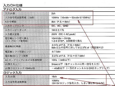
箱の表面には、大きく100MHzと描いてあるが、それは“サンプリング周波数”であって、“アナログ入力帯域幅”は、実際は、その1/10程度のはず。
資料の仕様を見ると、やはり帯域幅15MHzとなっている。(図9)
私自身は、この2〜3倍の30〜40MHz位は欲しいのだが。
改良・改造という手を考えても、高速のOPアンプを入れてフィードバックを多くすれば、“アナログ帯域幅”は広げられるだろうが、“サンプリング周波数”を上げるのは、メモリ・サイズとの絡みもあり、とても素人の手には負えないだろうと思う。
ま、そんなのは、敢えて、やりたいとは思わないが。
[令和二年五月二十四日/2020年5月24日]
KEYENCE NR-350データ収集器/PCオシロを、観察

この「PC110+NR350」は、高速オシロというには性能的には、やや不足なのだが、これの強みは、“ワンショットで記録が残せること”なので、もう少し使い込んでみたい。
面白いことに、冊子の「リファレンス・マニュアル」(登録すれば、KEYENCEサイトから入手可能)を見ていると、何だか懐かしさが湧いて来た。(図11)
それは、以前に「VisualBasic」で、プログラムを組んだことがあるので、それが出来ること(例えば、ツールバーや各種メニューの形式など)が、そのまま利用/実現されているからだろうと思う。
だからどうだというわけでもないが、余計にプログラムの中身やハードウェアの方にも興味が湧いたってことかな。
まぁ、早くハードウェアの中身を開けて(壊して)診たいのだが、その前に、もう少しその動作を見ておこうとしている。
「PC110」廃基板の動作の解析中だが、そのBIOSチップのOE#端子の信号を、ワンショットで捕捉してみた。(図12<クリック>)
もっと高速のサンプリングだと、矩形波のはずだが、三角波でしか捕捉出来ていない。
しかも、寸足らずの三角波もある。
33MHzクロックで動く信号は、100MHzサンプリングだと、取りこぼすことは無いと思うが、こうした寸足らずの波形になってしまう(のが辛い!)
でも、一旦データとして採取出来れば、後は、「PC110」で煮るなり焼くなり任意に出来るのが良い処。
今は、“アナログ波形”で見ているが、“ロジック波形”で捕まえられるがどうかも調べておきたいと思っている。
しかし、ターゲットとなる「PC110」廃基板の方の“配線パターンの細さ”が災いして、パターン剥がれを起こさないようにリード線を引き出さないといけないので、悩んでいる。
そして、今は休止中だ。
−−−−−−−−−−−−−−−−−−−−−−−−−−−−−−−−−−−−−−−
[English Note]
KEYENCE NR-350 data collector/PC oscilloscope, purchased
![Fig_1 : PC110」を「PCオシロ」に仕立てた <click>→Fig_2 : main units of the [NR-350]](fig/bynr350a.jpg)
I've always had a longing for analog memory scopes and digital oscilloscopes, and I thought that if I had the opportunity, I would buy it and use it.
I can get it at a low price if it has a narrow bandwidth of 1 to 2 MHz, but I did some bad shopping before and was punished.
The one with a bandwidth of 100MHz (which can record digital data) is so expensive that I just looked at it sideways and passed.
By chance, I saw a "You Tube" video about repairing an inexpensive junk digital oscilloscope and thought it was interesting.
However, due to the problem that the figure/case was too big and I have not a place to store it, I also stopped this.
But, I happened to find a compact KEYENCE data collector NR-350 (? 100MHz sampling), so I bought it (it's expensive but reluctant !). (\11,435 postage included)
This is originally a "data collector", but it can be used as a kind of "delay/recording type oscilloscope" because it can perform high-speed sampling. (Fig_2 <click>)
Therefore, it is perfect for observing single-shot phenomena !
This will be able to work on Win95/98, so it is also available in "PC110".
It will be an effective use for "PC110" of on resting .
However, this price is very delicate, and it cost more than 10,000 JPY even though it is an "antique measuring instrument" like Win95, Win98.
(Although there was also a "fool to buy" it here.)
Well, even the digital oscilloscopes with some narrow frequency band made by china are quite priced, so it may be necessary to endure this cost ?!
The problem is that if the frequency band is 100MHz sampling, the effective bandwidth will be about 1/10 to 1/5 of it, so "PC110" clock 33(~40)MHz is a little narrow.
After all, a simple test was not so bad, but a bit painful in high frequency. (Fig_1)
I'll try it a little more and see if it works.
−−−−−−−−−−−−−−−−−−−−−−−−−

+++ too big additional parts +++
When I tried to turn on the power and plugged the "AC adapter" into the horizontal sideset, it immediately fell out under its own weight. DOSUN♪ (big sound astonished)
I have to change other one immediately!
If it is "12V, 1.1A", it's enough to sweep in my junk box and get one, then throw the heavy one away.
...nummmm, There was none!
There wasn't unfortunately any suitable adapter with same size plug !?
Without stopping, I decided to remake only the plug part of a small "AC adapter", then I use it. (Fig_3)
In addition, the "noise suppression core" of the "PC-card-cable" was too large, so I also replaced it with a smaller one. (Fig_4 <click>)
Actually, it probably doesn't need two, so considering the situation, I'm thinking of setting one to zero.

+++ Install data processing software +++
Initially, I was concerned that the software was provided as a "floppy disk".
This is because there is no guarantee that the "floppy disk" will be altered or damaged.
However, there was no need to worry about it, as the registrants still have services such as Update (MV107.exe).
By the way, it seems that the successor model to this is not a "PC oscilloscope", but rather a high-performance product of a "data collector".
As a "data collection PC", I decided to use "PC110".
There was no particular problem in incorporating "MEGA VIEW" software in Win95 and Win98.
(I didn't try Win2000, etc., why did it not work on another machine equipped with Win10 even if I installed it?!)
At the time embedding in "PC110", I do not know how to allocate the "PC card driver" well, and while I confuse, "TFT display" does not display properly, which may be troublesome.
(The cause is the problem of "startup sequence" of "PC110".
If the contact condition of the coin battery terminals become bad, the startup sequence will be easily reset, so "ct65535a.exe /l" on the CF does not work and the LCD display does not appear.)
In the end, I was able to incorporate all of them into "PC110" equipped with Win85, Win98 (Fig_6 <click>) and operate them. (Fig_5)
As an aside, I used for installing an old FDD I bought at Flea Market recently.
It couldn't use to boot "PC-DOS" on "(once dameged) PC110", but it seems to be no problem as long as I use it on Win95, Wi98.
(I think that it may be caused by defect of the BIOS chip itself.)

+++ Verification of high frequency waveform +++
The 1KHz standard waveform could be displayed normally for both CH1 and CH2. (Obviously, not true junk.)
This product had the problem that one of the two probes was broken.
Obviously, the seller's (confident) lack of explanation.
As a test, I looked at the CLK terminal (33MHz) of the clock oscillator of "PC110". (Fig_8 <click>)
When data is sampled with 100MHz, if it is a "33MHz waveform", it will be missed by about 1/3, so a sine wave should be noise-like. (Fig_7)
It may be something like this in terms of performance.

+++ Confirmation of specifications +++
On the surface of the box, it is largely drawn as 100MHz!(?)
But it is the "sampling frequency", and the "analog input bandwidth" should actually be about 1/10 of that.
Looking at the specifications of the material, the bandwidth is still 15 MHz. (Fig_9)
I myself want 30 to 40MHz, which is 2 to 3 times as much as this.
I don't intend to improve or remodel it, but if I put in a high-speed OP amplifier and increase feedback, the "analog bandwidth" will be widened.
However, the "sampling frequency" should be increased by the memory I think it would be very difficult for an amateur to handle.
[2020/5/24]
KEYENCE NR-350 data collector/PC oscilloscope, observed

This "PC110+NR350" is a bit lacking in performance as a high-speed oscilloscope, but its strength is "recording in one shot", so I'd like to use it a little more.
Interestingly, when I looked at the "Reference Manual" in the booklet (registered, it is available from the KEYENCE site), I found something nostalgic. (Fig_11)
Since I have previously made a program with "Visual Basic", what I can do (for example, the toolbar and various menu formats) can be used as it is.
I think it is because it has been realized by the VB.
So it doesn't matter, but I was more interested in it.
Well, I want to open(? teardown) the contents of the hardware as soon as possible, but before that, I'm trying to see how it works.
"PC110" I am analyzing the operation of the waste board, but I tried to capture the signal of the OE# pin of the BIOS chip with one shot. (Fig_12 <click>)
If it is a faster sampling, it should be a rectangular wave, but it can be captured only by a triangular wave in this case.
Moreover, there are some triangular waves that are not too short.
I think that a signal moving with a 33MHz clock will not be missed if it is 100MHz sampling, but it will have such a short waveform (it is painful!)
However, once I can collect it as data, it is good to be able to boil it or bake it with "PC110" such as FFT solution.
Right now, I'm looking at "analog waveforms", but I'd like to investigate how they can be caught by "logic waveforms."
However, the "PC110" waste board that is the target suffers from the "thinness of the wiring pattern", and we have to pull out the lead wire so that the pattern does not peel off.
... Now, I topped it.


![Fig_1 : PC110」を「PCオシロ」に仕立てた <click>→Fig_2 : main units of the [NR-350]](fig/bynr350a.jpg)


