In the IBM 5150 (IBM PC), the failure of any chip in the first bank of RAM, bank 0, results in what appears to be a 'dead' motherboard.
Click here to see a diagram that shows the four RAM banks. Bank 0 is the soldered-in bank.
Piggybacking is a technique that can sometimes reveal a faulty RAM chip.
Basically, a known-good RAM chip is obtained, then one by one, piggybacked on each of the RAM chips in bank 0.
After each move of the good RAM chip, the motherboard is powered on, and if the motherboard 'springs to life', then the faulty RAM chip in bank 0 has been identified.
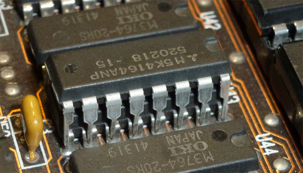
When piggybacking, take time to ensure that all 16 pins are making contact.
Warning
Chips can be damaged by electrostatic discharge (ESD) from your body. See here.
Limitations
* A good electrical connection needs to be made between the two chips. On some chips, oxide build-up on the pins may cause poor electrical connection.
* RAM chips can fail in different ways. The piggybacking technique is not effective on chips that have failed in particular ways. One example is shown here.
Multiple failures
If the motherboard was recently working and then stopped, and if the failure cause is a RAM chip in bank 0, then there will only have been one chip that has failed.
But if the history of the motherboard is unknown to you (e.g. you bought the motherboard from eBay, in a faulty condition), then the motherboard could have more than one faulty RAM chip in its banks.
The implications of that are important:
1. A RAM chip that you obtained from one of the other RAM banks, thinking that it must be 'good', might in fact be 'bad'.
2. Bank 0, the soldered-in bank, might contain more than one faulty RAM chip. I think that is very rare (but I have even encountered it myself).