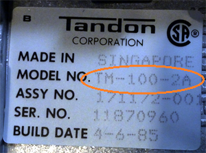
Tandon TM100-2 in IBM 5150/5155/5160 - Known Problems/Issues
The TM100-2 is a double sided, 48 TPI (tracks per inch), of 40 tracks per side.
Ideally, you know that your TM100-2 is faulty. You would determine that by substituting the drive with a known working drive (compatible with the TM100-2).
That helps rule out other possible causes of floppy related problems, e.g.
• Faulty floppy controller
• Faulty floppy cable (or incorrect cable)
• Floppy controller has dirty edge connectors
• ISA slot has dirty edge connectors
Incorrect floppies
Some people are unaware that not all types of 5.25" floppies can be used.
The Tandon TM100-2 is designed to use 5.25" floppies of the following characteristics:
• Double sided (2S) (or DS)
• Double density (2D) (or DD)
The floppy controller used in the IBM 5150 and 5160 adds another requirement; the use of soft sectored floppies.
These floppies (2S, 2D, soft sectored) are commonly referred to as '360K' floppies, because DOS (version 2.0 and later) formats them to 360 KB. Their unformatted capacity is 500 KB.
Some examples of suitable floppies are shown here.
Improperly written-to floppies
Although it is possible to write to, which includes formatting, a double density floppy in a high density (HD) drive, the result is floppy that does not conform to the double density standard.
Such floppies may not be able to be read by double density drives such as the TM100-2.
More information on this is at here.
Deteriorated lubrication
This is commonly seen on the rails that the head carriage slides up and down on. Deteriorated lubrication there results in the inability of the head carriage to move properly, or in extreme cases, not move at all. By hand (and with power off), you should be able to freely move the head carriage along its rails. You will experience some slight resistance presented by the stepper motor.
What is required is to clean the rails of the old lubricant, then followed by application of new lubricant. Myself and others have found a silicone based lubricant to be satisfactory. I sometimes use silicone spray, but there is a tendency for the spray to get to areas where it should not go. Otherwise, I use silicone grease, something that I also use to get rid of any squeak sound from the drive's front panel latch.
If in any doubt, clean/relubricate the rails. The clean/relube is a worthwhile maintenance activity even if it doesn't fix a faulty drive.
'Dirty' read/write heads
Background: In normal floppy drive operation, the drive's heads make contact with the oxide coating on floppies.
LIGHT/MODERATE
In normal use of 'good' floppies, particles of oxide come off the floppy surface and stick to the heads. This is normal. Over time, as the oxide builds up on the heads, the ability of the floppy drive to read/write to a floppy becomes more and more problematic. For example, you may start to see an occasional read error on (good) floppies. 'Head cleaning' floppies (example) were created to remove this low level of oxide build-up.
In the eighties, I remember much debate about how often that head cleaning floppies should be used (as part of preventative maintenance). The issue is that head cleaning floppies are abrasive, and therefore should not be used too often. But what is too often? Makers of cleaning floppies have an interest in you consuming lots of their product, and so their advice is not to be trusted.
HEAVY
Some old floppies have deteriorated to the point where their surface oxide literally wipes off, depositing itself in a thick layer on the drive's heads. This makes the drive either unusable, or very close to unusable.
Head cleaning floppies are not designed to cope with that amount of oxide build-up. Well, with a single cleaning operation that is. You may need to use the head cleaning floppy, say, 20 to 50 times, maybe more. It will depend on the ability of the cleaning floppy, and on how heavy the build-up is.
What I use for this kind of heavy oxide build-up is isopropyl alcohol on a cotton tip, being very careful not to damage the heads. In my opinion, that combination seems to 'cut through' the oxide at a faster rate. Even so, do not expect that a thick layer of oxide will be removed in just a couple of passes of the cotton tip. I have had a bad floppy put down an oxide layer that took a couple of minutes of 'isopropyl alcohol on a cotton tip' cleaning to remove.
Incorrect termination
The TM100-2 has an optional terminator. It is pictured at here.
Click here to see the situations in which it is either fitted or removed. This is important, because certain configurations of improper termination can result in improper drive operation.
If you need a replacement, the TM100-2's terminator is electrically described at here.
Incorrect head alignment
Part of the 360K floppy 'standard' includes where exactly on the floppy that the tracks are located (in relation to the center of the floppy). At the factory, to match that part of the standard, the drives are taken through a process known as 'radial head alignment'.
Over a long time, usually many years, the heads in the TM100-2 can (can, but do not always) drift out of alignment.
This is indicated if you see both of the following:
1. 360K floppies that you have formatted in the drive work well in the same drive, and
2. The drive does not read good 360K floppies that were formatted on a different 360K drive (a known good aligned drive).
Performing a radial head alignment is not easy, and there is the potential to make the situation worse than it is presently. For that reason, my strong recommendation is not to attempt a head alignment unless you know that your drive has a head alignment problem.
The manufacturer's head alignment procedure involves the use of an oscilloscope and a special factory-created alignment floppy (cannot be copied). Most computer owners have neither of those, nor the knowledge of how to use them. If you do not have those, then maybe the procedures detailed on the link here will help you.
Stepper Motor
Some people have reported a stepper motor that was not stepping properly, and the answer for them was to squirt WD40 into the stepper motor.
Incorrect spindle speed
Checking for correct spindle speed on a TM100-2 is easy.
Underneath the drive, you will see the spindle's flywheel (photo). On it are two sets of ring patterns, one labelled '50Hz' and the other labelled '60Hz'. The one you are to use corresponds the frequency of mains electricity (house electricity) used in your country. Position the drive so that the flywheel is exposed to strong (repeat: strong) fluorescent light (repeat: fluorescent). Now, insert a floppy, then perform an operation that results in the spindle (and thus the flywheel) turning. The pattern that corresponds to your country's mains electricity frequency should not move. Well, there is going to be a little bit of movement, but it should not be much.
To adjust spindle speed, use a screwdriver to adjust R4 (photo) on the servo board, the board located on the rear of the drive.
To note is that I once encountered a drive where the flywheel's securing screw was loose. As expected, tightening that screw fixed the speed problem.
Consider too, that maybe the spindle needs lubrication.
Bent posts
On the logic board are test points, in the form of vertically standing posts. Two of the posts are shown in the photo at here. If the drive has not been stored nor shipped properly, then you may find that one or more posts are bent over touching another part of the circuitry.
Dirty hub clamp
Member Tezza of the VCFF experienced this. He explains it here.
Short-circuit capacitors
If your TM-100-2A has a short-circuit somewhere in it, overloading the host computer's power supply, then based on my experience, I suggest that your first suspects should be capacitors C36 and C43.
C36 and C43 are tantalum type capacitors, each having the value of 4.7μF/16V. Substitute an aluminium electrolytic type if you want. Also, if you want, you can use a higher voltage rated version, e.g. 4.7μF/25V. These capacitors are polarised, so make sure that the positive leg of the replacement capacitor goes into the hole marked with a '+' sign.