| Home |
| IMPORTANT: | The following is specific to the IBM 5170 (IBM AT). |
| Certain portions will not be applicable to clones that were made of the IBM 5170. |
| NOTE: | Execution of tests is not always done in numerical order. |
| For example, the hard drive tests are done in order of 1782, 1780, 1781, 1790, 1791 |
| Error | Observed by user | Description | ||
|---|---|---|---|---|
| 1 long beep then 2 short beeps | Some causes: • Video card is faulty. • Video card is has a poor connection to the motherboard - try re-seating the card. • Video card is has a poor connection to the motherboard - try cleaning the ISA contacts. • 'Interference' from another ISA card - try removing all ISA cards except for the video card. |
|||
| 1 long beep then 3 short beeps | The BIOS expansion ROM on an IBM EGA card is known to generate this if it discovers that the card has faulty RAM. |
|||
| The RAM count-up happens on-screen, but no further progress |
On a type 3 motherboard, a known cause is having an MDA card (monochrome) fitted, but the motherboard's video switch SW1 is set to the CGA (colour) setting. |
|||
| 101 | 101-System Board Error | IBM describes this as 'INTERRUPT FAILURE'. |
||
| 102 | 102-System Board Error | IBM describes this as 'TIMER FAILURE'. |
||
| 103 | 103-System Board Error | IBM describes this as 'TIMER INTERRUPT FAILURE'. |
||
| 104 | 104-System Board Error | IBM describes this as 'PROTECTED MODE FAILURE'. |
||
| 105 | 105-System Board Error | IBM describes this as 'LAST 8042 COMMAND NOT ACCEPTED'. |
||
| 106 | 106-System Board Error | IBM describes this as 'CONVERTING LOGIC TEST'. |
||
| 107 | 107-System Board Error | IBM describes this as 'HOT NMI TEST'. |
||
| 108 | 108-System Board Error | IBM describes this as 'TIMER BUS TEST'. |
||
| 109 | 109-System Board Error | IBM describes this as 'LOW MEG CHIP SELECT TEST'. |
||
| 161 | 161-System Options Not Set-(Run SETUP) | IBM describes this as 'DEAD BATTERY'. Note that simply fitting a good battery is alone, not enough to remove the 161 error. One also needs to then complete the SETUP procedure. The combination of those two actions should remove the 161 error. Some possible causes: • Battery is dead/low - replace it and then run the SETUP procedure. • A dead/low battery was replaced with new but the SETUP procedure has yet to be done. • Faulty motherboard. |
||
| 162 | 162-System Options Not Set-(Run SETUP) | IBM describes this as 'CMOS CHECKSUM ERROR', but that is only a partial description. Either, a SETUP configuration (CMOS SETUP) checksum problem, or some other configuration issue. Some possible causes: • A hiccup of some kind has corrupted SETUP configuration (CMOS SETUP). Correct this by running the SETUP procedure. • Battery is dead/low. Some 5170 motherboards, for unknown reason, don't produce a 161 error. Check/replace battery, and then run the SETUP procedure. • A CGA video card is fitted, but the SETUP configuration (CMOS SETUP) is set for MDA (monochrome), or 'special' (EGA/VGA). • An MDA ( monochrome) video card is fitted, but the SETUP configuration (CMOS SETUP) is set for CGA, or 'special' (EGA/VGA). |
||
| 163 | 163-Time & Date Not Set-(Run SETUP) | IBM describes this as 'CLOCK NOT UPDATING', but that is only a partial description. Either, there are invalid clock (date/time) values in the CMOS/RTC chip, or the clock in the CMOS/RTC chip is not ticking over (not advancing). Some possible causes: • A hiccup of some kind has corrupted the clock values. Correct this by running the SETUP procedure. • The SETUP procedure was started but not finished. • Motherboard failure (in CMOS/RTC related circuitry). |
||
| 164 | 164-Memory Size Error-(Run SETUP) | The amount of base RAM or expansion (extended) RAM discovered by the POST is different than the amounts recorded in SETUP configuration (CMOS SETUP). Some possible causes: • User has added RAM but failed to then perform the SETUP procedure. • User ran the SETUP procedure, and during that procedure, entered incorrect amounts for the RAM. • Faulty RAM (faulty in a way that unfortunately, leads the POST to believe that there is less RAM than fitted). |
||
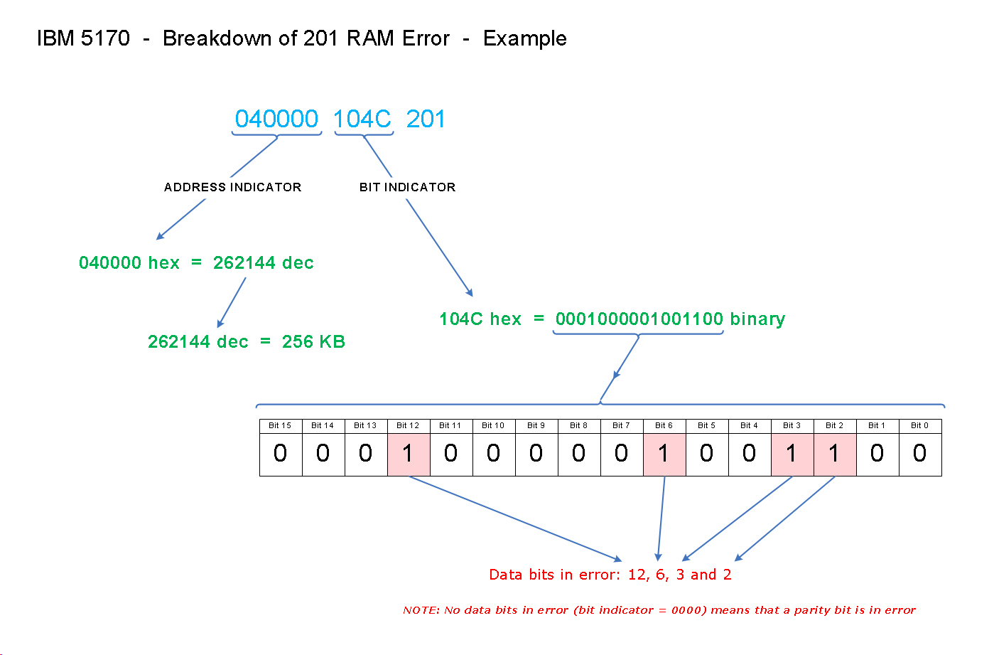
| 201 | 201-Memory Error | RAM related problem. Displayed on screen in the format of "AAAAAA BBBB 201-Memory Error", where AAAAAA is the hexidecimal address (in bytes) of the failing word and BBBB shows which bits in the word have failed. You can use the diagram here to calculate the failing bit/s, and the address as a KB figure. Sometimes, you may see an address that is one word beyond the actual failing address, e.g. 080002 instead of 080000
|
||
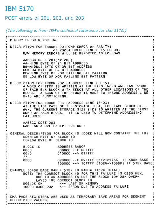
| 202 | 202-Memory Address Error | Memory related problem concerning address bits 0 to 15. IBM's description is at here. |
||
| 203 | 203-Memory Address Error | Memory related problem concerning address bits 16 to 23. IBM's description is at here. |
||
| 301 | 301-Keyboard Error | Keyboard problem. If the error is preceeded by a byte, e.g. "21 301-Keyboard Error", that indicates that a key is stuck down on the keyboard. The byte indicates which key. If instead, the error is just "301-Keyboard Error", that indicates a general keyboard error. Some possible causes: • No keyboard. • Wrong type of keyboard - AT class keyboard required - PC/XT class keyboards will not work. • Faulty keyboard. • Faulty motherboard (specifically the keyboard interface circuitry on it). • In certain AT clones, a keyboard error can be caused by the front panel keyswitch being in the 'locked' position. • In certain AT clones, a keyboard error can be caused by a blown keyboard fuse on the motherboard. (Note: The IBM 5170 does not have a keyboard fuse.) |
||
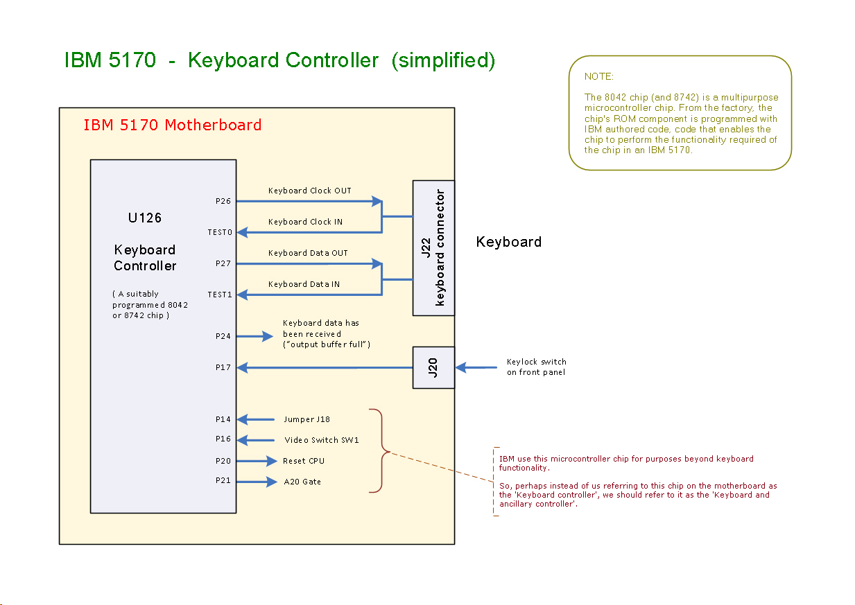
| 302 | 302-System Unit Keylock is Locked | The POST interrogated the keyboard controller chip on the motherboard to get the status of the 5170's keylock switch (on front panel). It was indicated that the keylock is in the locked position. Some possible causes: • Keylock is in the locked position. • Keylock is in the unlocked position, but the keylock switch is faulty (faulty in a way that has closed the contacts on motherboard connector J20). • Partially faulty keyboard controller chip on motherboard (faulty in a way that results in a read of its 'P17' pin being reported incorrectly). To rule out the keylock, simply remove the plug on motherboard connector J20, as shown removed in the right-hand photo at here. If the 302 error no longer appears at power on of the 5170, it means that the keylock is the 302 cause. |
||
| 303 | 303-Keyboard Or System Unit Error | Power off the IBM 5170, then remove the keyboard, then power the IBM 5170 back on. If the 303 error has gone, it means that the keyboard is faulty (faulty in a particular way). If the 303 error remains, it means that the motherboard is faulty (faulty in a particular way). |
||
| 304 | 304-Keyboard Or System Unit Error | IBM describes this as 'KEYBOARD CLOCK LINE HIGH'. Power off the IBM 5170, then remove the keyboard, then power the IBM 5170 back on. If the 304 error has gone, it means that the keyboard is faulty (faulty in a particular way). If the 304 error remains, it means that the motherboard is faulty (faulty in a particular way). |
||
| 401 | 401-CRT Error | A known cause: Having only a CGA video card fitted, but motherboard switch SW1 is incorrectly set to the MDA position (rear). |
||
| 501 | 501-CRT Error | A known cause: Having only an MDA (monochrome) video card fitted, but motherboard switch SW1 is incorrectly set to the 'CGA' position (front). |
||
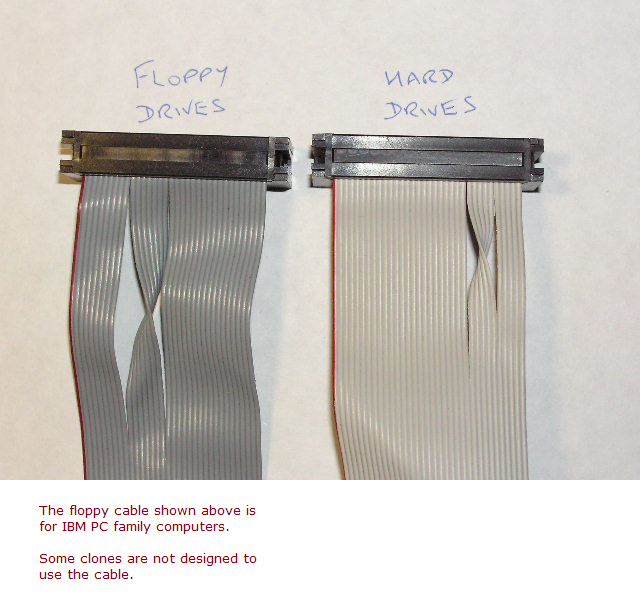
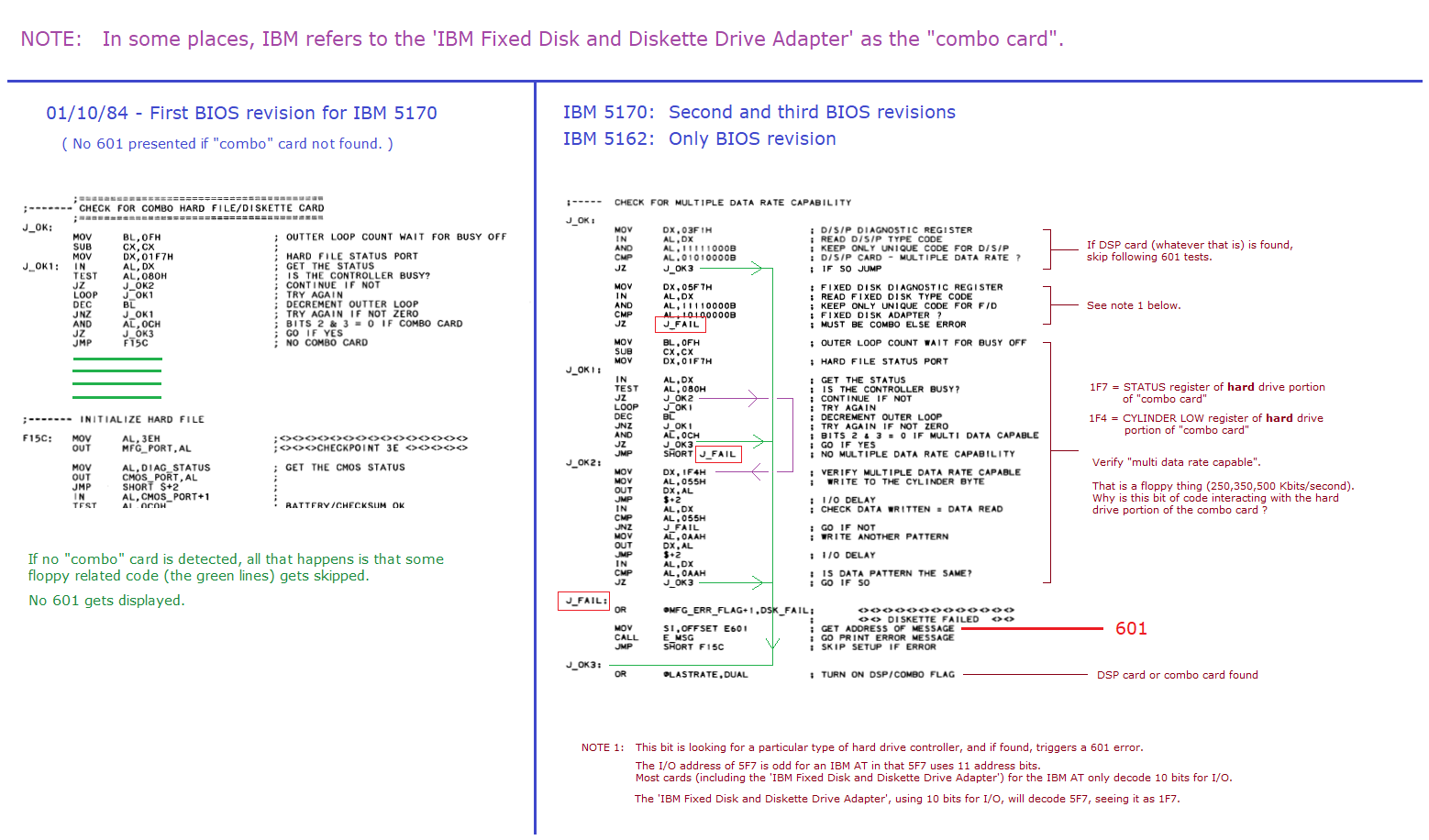
| 601 | 601-Diskette error | Some possible causes: • POST can't find the floppy portion of the IBM Fixed Disk and Diskette Drive Adapter • Wrong type of twisted cable is being used - hard drive type instead of floppy drive type. (photo of difference) • Floppy drive A: - faulty • Floppy drive A: - does not have power to it (either +5V or +12V, or both). • Floppy drive A: - jumpered incorrectly for the 5170 • Floppy drive A: - a make-model that is incompatible with the 5170 • BIOS issue: Are you seeing the 601 after removing the IBM Fixed Disk and Diskette Drive Adapter and substituting it with something else ? There is something in the second and third BIOS revisions of the 5170 that expects the IBM Fixed Disk and Diskette Drive Adapter. The first BIOS revision does not have the issue. |
||
| 602 | 602-Diskette Boot Record Error | IBM describes this as 'DISKETTE BOOT RECORD IS NOT VALID'. |
||
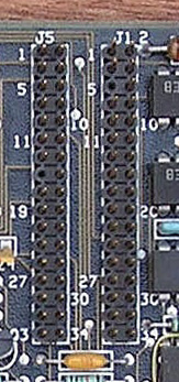
| 1780 | 1780-Disk 0 Failure | The 5170's POST, upon seeing that a hard drive is included in the SETUP configuration (CMOS SETUP), asked the hard disk controller to perform an 'internal diagnostic' (see 1782 error). That passed. The POST then asked the controller to issue a 'Recalibrate drive' command to the first hard drive (C:). The 1780 error was displayed because that command failed. Some possible causes: • Control cable (34 pin) is missing. • Control cable (34 pin) is no longer seated correctly on controller or drive. • Control cable (34 pin) is faulty. • On the controller, control cable (34 pin) accidentally connected to J1 (for floppy drives) instead of J5 (for hard drives). See diagrams at here. • On the controller, control cable (34 pin) is connected to J5 upside down. See diagrams at here. • Drive Select jumper on hard drive is in wrong position for the type of control cable being used. See diagrams at here. • A twisted control cable is being used but is the wrong type - floppy drive type instead of hard drive type. (photo of difference) • Hard drive does not have power to it (either +5V or +12V, or both). • Hard drive is faulty. • Hard drive controller card is faulty (even though it earlier passed its 'internal diagnostic' [test 1782]). • Hard drive controller card is in an 8-bit slot (example: 5170 slot 7) instead of a 16-bit slot. • Hard drive controller card has 'dirty' edge connectors (ones that affect this test). |
||
| 1781 | 1781-Disk 1 Failure | Per 1780 error, but for second hard drive (D:) |
||
| 1782 | 1782-Disk Controller Failure | The 5170's POST, upon seeing that a hard drive is included in the SETUP configuration (CMOS SETUP), asked the hard disk controller to perform an 'internal diagnostic'. The 1782 error was displayed because, either the controller responded in the negative, or the controller did not respond within a minute. Some possible causes: • Hard drive controller card missing. • Hard drive controller card is not seated properly in its slot. • Hard drive controller card has 'dirty' edge connectors (ones that affect this test). • Wrong type of hard drive controller card is fitted (example: XT class controller is fitted). • Faulty hard drive controller card. • Hard drive controller card is incorrectly jumpered (example: set for secondary address range, not primary). |
||
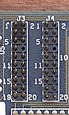
| 1790 | 1790-Disk 0 Failure | The 5170's POST, upon seeing that a hard drive is included in the SETUP configuration (CMOS SETUP), asked the hard disk controller to perform an 'internal diagnostic' (see 1782 error). That passed. The POST then asked the controller to issue a 'Recalibrate drive' command to the first hard drive (see 1780 error). That passed. The POST then asked the controller to read certain sectors on the first hard drive. The 1790 error was displayed because one of those reads failed. Some possible causes: • Data cable (20 pin) is missing. • Data cable (20 pin) is no longer seated correctly on controller or drive. • Data cable (20 pin) is faulty. • On the controller, data cable accidentally connected to J3 (for D:) instead of J4 (for C:). See diagrams at here. • On the controller, data cable is connected to J4 upside down. See diagrams at here. • A new hard drive was fitted but its low-level format does not match that of the controller. Low level format the drive after fitment. <----- Common, if new drive fitted • Hard drive has fewer cylinders or heads than the drive C: type in the SETUP configuration (CMOS SETUP) indicates. • Hard drive C: is faulty. • Faulty hard drive controller card (specifically the drive data processing area). • Hard drive C: is getting +12 volts, but not the hard drive controller card. See note 1. • The hard drive controller card is not getting -12 volts. See notes 2 and 3. |
||
| 1791 | 1791-Disk 1 Failure | Per 1790 error, but for second hard drive (D:) |
||
| PARITY CHECK | Intermittent and unlike below, there is no '1' nor '2' following 'PARITY CHECK'. A virus is known to display this. (The IBM BIOS in an IBM 5170 always displays a 1 or a 2 after PARITY CHECK.) |
|||
| PARITY CHECK 1 xxxxx |
A parity error occurred when an address in motherboard RAM was read. 'xxxxx' will either be the address where the parity error occured, or it will be five question marks if the address could not be determined. |
|||
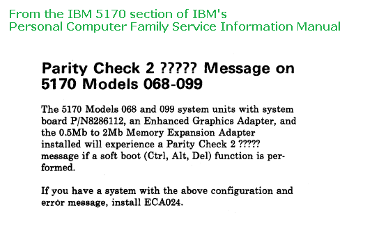
| PARITY CHECK 2 xxxxx |
A parity error occurred when an address in expansion card hosted RAM was read. 'xxxxx' will either be the address where the parity error occured, or it will be five question marks if the address could not be determined. PARITY CHECK 2 with five question marks is also known to occur in the specific situation stated at here. |
| Note 1 | Maybe the +12V connection to the motherboard is bad. Try remove/refit connector P8. |
| Note 2 | Check -12 volts out of power supply. This check should not be required if you have the genuine 5170 power supply, because the corresponding lack of a POWER GOOD signal would not have allowed the motherboard to start. |
| Note 3 | Maybe the -12V connection to the motherboard is bad. Try remove/refit connector P8. |