| Parent |
| WARNING: | This web page is about the IBM Fixed Disk Adapter. Other controllers can behave differently. |
| Step 1: | "RESET CONTROLLER" via function HD_RESET_1. If unsuccessful after 37 (25h) attempts, display 1701 then exit. See note 1. |
| Step 2: | "CONTROLLER RAM DIAGNOSTIC" via INT 13H FUNCTION 12H. If that fails, display 1701 then exit. See note 2. |
| Step 3: | "CONTROLLER INTERNAL DIAGNOSTIC" via INT 13H FUNCTION 14H. If that fails, display 1701 then exit. See note 2. |
| Step 4: | If "KEYBOARD RESET UNDERWAY" then change the value of a timer (specifically "TIMER_LOW"). See note 3. |
| Step 5: | Now, both a "RESET CONTROLLER" (via function HD_RESET_1) followed by a "TEST DRIVE READY" of hard drive 0 (via INT 13H FUNCTION 10H) need to be successful within a certain period of time. If that is not achieved, display 1701 then exit. See note 8. |
| Step 6: | "RECALIBRATE" of hard drive 0 via INT 13H FUNCTION 11H. If that fails, display 1701. See note 4. |
| Step 7: | "INITIALIZE DRIVE PAIR CHARACTERISTICS" via INT 13H FUNCTION 09H. If that fails, display 1701. |
| Step 8: | "WRITE SECTOR BUFFER" for hard drive 0 via INT 13H FUNCTION 0FH. See note 5. |
| Step 9: | Look to see if controller is in a host computer or in a 5161 expansion unit. If in host computer, adjust the value of a timer (specifically "TIMER_LOW") accordingly. See note 6. |
| Step 10: | If an IBM extender card is present, enable it. See note 7. |
| Step 11: | See if a second hard drive (hard drive 1). If present, "RECALIBRATE" it. See note 4. |
| WARNING: | This web page is about the IBM Fixed Disk Adapter. Other controllers can behave differently. |
| Note 1 | Function HD_RESET_1 does not call INT 13H FUNCTION 00H. Essentially, HD_RESET_1 is the INT 13H FUNCTION 00H code, but with many (100H) retries before failure. The INT 13H FUNCTION 00H code has no retries. |
| Note 2 | No hard drive needs to be attached to the IBM Fixed Disk Adapter for this function to pass. Proven by my experimentation. |
| Note 3 | A 'warm boot' (e.g. CTRL-ALT-DEL). |
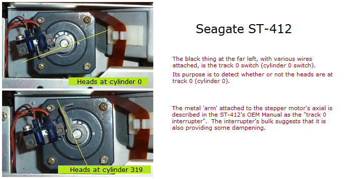
| Note 4 | 'Recalibrate' means move/step the drive's heads to cylinder 0. We know from the 'Function 11h' information at here that the IBM Fixed Disk Adapter does not read any sectors during a 'recalibrate' operation; it selects the drive, then simply steps the heads outwards until the MFM drive asserts the TRACK 0 pin on its 'control' connector (i.e. heads are on cylinder 0). |
| Note 5 | Does not write to disk. Simply populating the controller's sector buffer (a buffer stored in part of the controller's RAM). See here. |
| Note 6 | Why this late? If the expansion ROM needs to compensate for the location of the IBM Fixed Disk Adapter, then surely this step should have been done very early in the sequence. |
| Note 7 | Unsure why this is required in the expansion ROM, because the IBM extender card enables itself at power-on time. |
| Note 8 | At the instant that the MFM drive receives power (+5V and +12V), it is not ready for operations. Before it becomes ready, the drive does a self test, which includes waiting for the spindle to reach the proper speed (up-to-speed). The maker of the MFM drive decides what to include in the self test. As part of the self test (and when the spindle is up-to-speed), the MFM drive may move the heads in order to test the track 0 switch. Example behaviour of my Seagate ST-412 drive: - No control nor data cables (i.e. I am supplying power only to the drive). - If the heads are not at track/cylinder 0 when power is applied, then about 15 seconds later, I see the heads (actually, the track 0 interrupter) move to track/cylinder 0. - If the heads are at track/cylinder 0 when power is applied, the heads do not move at all. (The ST-412 OEM manual indicates that 15 seconds is the typical time required for the ST-412 to become ready.) |