VGA Output
from STM32F4 Discovery board
(Last updated 3 Jan 2015)
I love the web! There are so many cool projects out there, and
some, with a tweak or two, get me where I want to go quickly, saving a
ton of time and effort. Case in point: The Artektit page on VGA
output using a 36-pin STM32.
The Artekit gang developed a minimalist VGA implementation using one of
the boards they sell, with a 72 MHz STM32F103 device on-board. I
say "minimalist" because it uses just the board and a VGA connector,
but you get 800x600 monochrome VGA out. Then they added code for
doing simple graphics and text generation, and all VGA timing is done
using DMA writes to an SPI channel. Their design has negligible
impact on processor resources, so you could drop their VGA drivers into
your project and see almost no hit to throughput.
Because of memory constraints in the chosen device, they only have room
for 400x200 pixels. They implement this by assigning a 10K frame
buffer, then writing out the pixels as 200 lines of 50 bytes
each. Each pixel is sent twice and each line is sent three
times. The result satisfies the monitor's timing for 800x600 VGA,
but the effective graphics resolution is 400x200.
Enter the STM32F4 Discovery board. It has plenty of room for a
full 800x600 frame buffer and runs far faster than the original '103
device. All that is needed is to port their code from the '103
device to the STM32F4 processor and modify it to display a full 800x600
monochrome VGA. VGA output from a $15 board. With almost no
CPU through-put hit. What's not to like?
The porting effort
I started with a download of the Artekit files from the above
link. I have to say the code is impressive. The comments
told me most of what I needed to know, and the structure was well
thought out.
I'm only addressing items I changed or added to the Artekit
project. Some of this won't make sense unless you also read
through the Artekit page; you've been warned.
The first task was selecting the I/O pins to use on the S4D
board. Here is what I ended up with:
Artekit
|
Discovery
|
Notes
|
PA1
|
PA1
|
Vertical sync
|
PA7
|
PB5
|
VGA pixel data (GREEN)
|
PA8
|
PA8
|
Horizontal sync
|
GND
|
GND
|
Ground
|
That's it! Four wires and you're good.
I switched my pixel data output to PB5. I needed a MOSI signal
from SPI1 and my only choices that supported DMA channels were PA8 and
PB5, and PA8 was already assigned.
The VGA timing requirements are widely available on the web; one of the
best sites is TinyVGA.com, which has
pages devoted to many of the VGA resolutions. The Artekit code
uses a 56 Hz refresh rate, and I stuck to that. From the TinyVGA
site, the important 800x600 56 Hz timing info is:
General timing
| Screen refresh rate |
56 Hz |
| Vertical refresh |
35.15625 kHz |
| Pixel freq. |
36.0 MHz |
Horizontal timing (line)
Polarity of horizontal sync pulse is positive.
| Scanline part |
Pixels |
Time [µs] |
| Visible area |
800 |
22.222222222222 |
| Front porch |
24 |
0.66666666666667 |
| Sync pulse |
72 |
2 |
| Back porch |
128 |
3.5555555555556 |
| Whole line |
1024 |
28.444444444444 |
Vertical timing (frame)
Polarity of vertical sync pulse is positive.
| Frame part |
Lines |
Time [ms] |
| Visible area |
600 |
17.066666666667 |
| Front porch |
1 |
0.028444444444444 |
| Sync pulse |
2 |
0.056888888888889 |
| Back porch |
22 |
0.62577777777778 |
| Whole frame |
625 |
17.777777777778 |
All of the setup for this timing happens in the file video.c. The
code uses two channels of TIM1. Channel 1 generates the Hsync
pulse and channel 2 generates the Hsync plus back porch pulse.
Additionally, TIM1 is set as the master for TIM2.
The code also uses two channels of TIM2. Channel 2 generates the
Vsync pulse and channel 3 generates the Vsync plus back porch
pulse. Because TIM2 is slaved to TIM1, it automatically fires in
lock-step with events generated by TIM1, ensuring that horizontal and
vertical timing are properly synced.
Pixel data appears on MOSI of SPI1. SPI1 is fed pixel data via
DMA, which is triggered by completion of the Hsync plus back porch
event on TIM1. Each DMA transfer writes one line of pixel data to
SPI1; data appears on MOSI with no timing gaps.
When each DMA transfer completes, a small amount of code in the IRQ
handler updates the input pointer (M0AR) to point to either the next
line of pixel data or, if a full screen transfer just ended, the start
of the frame buffer.
The IRQ handlers for DMA, TIM1 and TIM2 contain the only run-time code
needed to keep the entire VGA output going; we're talking about 10
lines of code total. All work to generate timing and move the
pixel data is handled automatically by the timers and the DMA subsystem.
The pixel frequency is fixed at 36 MHz, which in turn sets the SPI
clock and there are a limited number of prescalers in that clock
range. I set the MCU system clock to 144 MHz, then used a /2
prescaler to get the need pixel clock.
Because the S4D has a much larger RAM pool than the original device, I
expanded the frame buffer to hold a full 800x600 monochrome
display. I also made slight modifications to the IRQ handlers to
allow for the expanded pixel stream and larger number of horizontal
lines. Because the original Artekit code was so well laid out,
these changes were obvious and easy.
I left the Artekit demo code intact. The demo looks almost
exactly as its creators left it, except the text appears in the
upper-left corner rather than the center, and the text is quite a bit
smaller though perfectly readable.
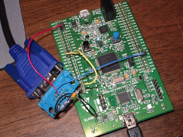
Here is a picture of the hardware:

Yes, I know, it looks pretty nasty. I'll clean it up on the next
hardware revision.
The photo does show one small mod I made to the wiring. The
Artekit writeup talks about using a resistor divider on the GREEN
input. Basically, I connected PB5 to a 120-ohm resistor, with a
47 pf capacitor wired across the resistor. The other end of the
resistor went to the GREEN input on the VGA connector. Finally, I
tied a 270-ohm resistor between the GREEN input and ground.
The Artekit page notes that they have driven a lot of monitors directly
from the 3.3V output of their micro, but it seemed to me using the
resistor divider would be a better choice.
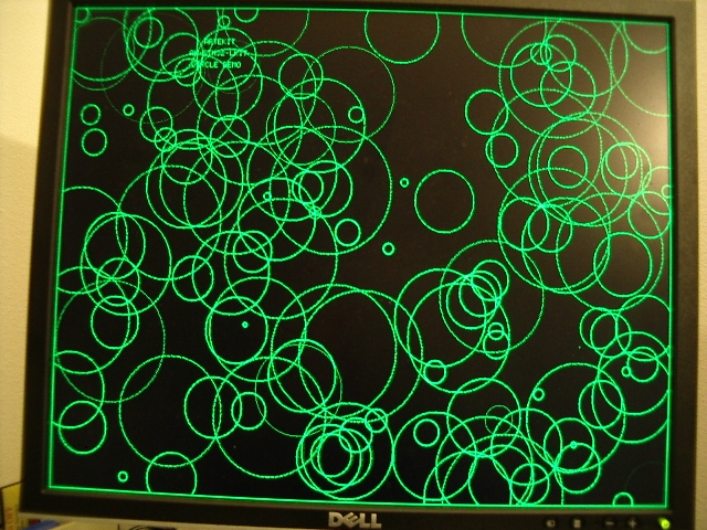
Here is a picture of the output on a Dell monitor:

This is part of the Artekit demo program and gives you an idea of the
display quality. You can just make out the original Artekit text
near the upper-left corner.
Issues
I hit a few snags during this effort, not the least of which was my
unfamiliarity with VGA signal generation and use of the STM32 DMA
subsystem.
One headache that came back almost immediately was the reason why I
haven't done any STM32 code in several months. The ST Micros Std
Peripheral Driver library just sucks. Whoever thought it was a
good idea to wrap a simple register change in a function call needs to
develop a few time-critical apps on an ATtiny and see how far that
concept gets you. The only thing I've seen that's worse is
Arduino code.
At one point in my development, I needed to push a stream of bytes out
the SPI, so I used one of the library's functions to write to the DR
register. The function introduced 250 ns gaps in the data
stream. Really? A 250 ns penalty for using your library
call? Not gonna happen. I switched to a direct write to the
register using a macro and the gap disappeared.
I see a lot of STM32 code on the web that uses library calls to
initialize subsystems, then switches to macros inside functional
code. That's pretty much what I did here. And I hated doing
even that, because I just knew the linker probably brought in 8K or so
of bloat from invoking these calls.
I ran into a problem with minor tearing (more like shimmering) of the
display, even when the display was not being modified by the code (so
this was not a issue with DMA accessing the frame buffer while the
mainline code was accessing it). I traced the problem to general
memory accesses not related to the frame buffer. I was using a
spin-loop to generate delays, like this:
void sysDelayMs(u32 dly)
{
int32_t
n;
int32_t
j;
for (n=0;
n<dly; n++)
{
for (j=0; j<20000; j++) ;
// rough guess, looking for 1 ms delay
}
}
The above code caused the display to distort and tear while the
mainline code was waiting for the delay to end. If I moved the
two timing variables into registers, like this:
void sysDelayMs(u32 dly)
{
register
int32_t
n;
register
int32_t
j;
for (n=0;
n<dly; n++)
{
for (j=0; j<20000; j++) ;
// rough guess, looking for 1 ms delay
}
}
the display became rock-solid and clean. I don't know enough
about the inner workings of the STM32F4 to know why the earlier code
affected the display. If anyone has an answer, please drop me an
email.
Summary
I've bundled all of my code into a single zip file. Like most of
my embedded projects, I used Visual Studio 2008 as the IDE and the
folder layout reflects that. In order to set up this code to
match your IDE, check through the Makefile (vga_artekit.mak); the
comments should help you as you edit the Makefile for your needs.
I'm assuming here that you already have CodeSourcery Lite++ installed
on your machine and you also have the ST Micros STM32F4 Discovery
support files installed. In my case, I installed the ST Micros
code here: C:\projects\STM32F4-Discovery_FW_V1.1.0\. Note that I
renamed any directories with spaces in their name to remove those
spaces. The spaces cause issues when I build within VS2008.
The code in this release is a working modification to the original
Artekit code, but I make no claims that this is bug-free or even high
quality. It works, it shows an excellent display, but I know it
needs more time and work from me. I'm releasing it so others can
use it as a starting point for their projects. As I update this
code, I'll try and keep this page updated, as well.
I started this project because I wanted VGA display of text from an
embedded microcontroller for the least effort, smallest throughput hit,
and lowest cost possible. Thanks to Artekit and ST Micros, I now
have the hardest part of that project done.
There's still plenty to do, of course. I need to tweak the font
file, wrap all of this code into a finished library, create text and
graphics APIs for my other projects to use, and probably some other
stuff.
But I am much farther along on my project than I could have hoped to be
without the headstart given by Artekit. Thanks, guys, for some
excellent code and a terrific project!
Here is the zip file of my project: vga_artekit.zip
Home

