Hacking the Adaptive Displays LED matrix board
(Last modified 24 Aug 2014)


Reverse-engineering an old piece of electronics gear can be a fun way to learn new (actually, old) design ideas, exercise your debugging and design skills, and save a useful piece of kit from the scrap heap.  And if that gear includes 1024 LEDs, even better!

My buddy, Warren, ended up with a pile of 16x32x2 LED matrix boards from a large 20-year old sign.  Each matrix unit contains a panel of 16x32 LEDs, selectable red or green, along with a large column driver board and a smaller row driver board; the row driver board includes the power transistors for powering the matrix.

Since Warren had no schematic, no manual, not even the name of the manufacturor, he figured he'd give one to me to play with.

A quick check on the web showed images similar to this board as made by Adaptive Displays, and that was literally all we found.  We were really on our own here.

The column driver board has two six-pin single-row connectors, one on each end of the board.  A couple of hours of probing with continuity checkers and we had a partial schematic of the controller board.  Since we did this independently, we ended up with two schematics, generally the same but each with some additional info.  Here is my schematic (PDF).

Basically, these boards are big-ass shift registers (BASRs).  Remember, these boards were built in the late '90s.  Micros were expensive back then, compared to the cost of a handful of CMOS logic.  The board designers went with 4094 serial-to-parallel latches and 4015 serial registers.  All of the timing and intelligence was off-loaded to a controller board (which we don't have).  The only control lines available were the six pins on the input connector.

Part of the controller board and some LED matrices

Here I've removed a couple of the 8x8 LED matrix boards to show part of the column driver PCB.  The column driver board contains eight identical sections of wiring, plus a bundle of large wires for LED power.


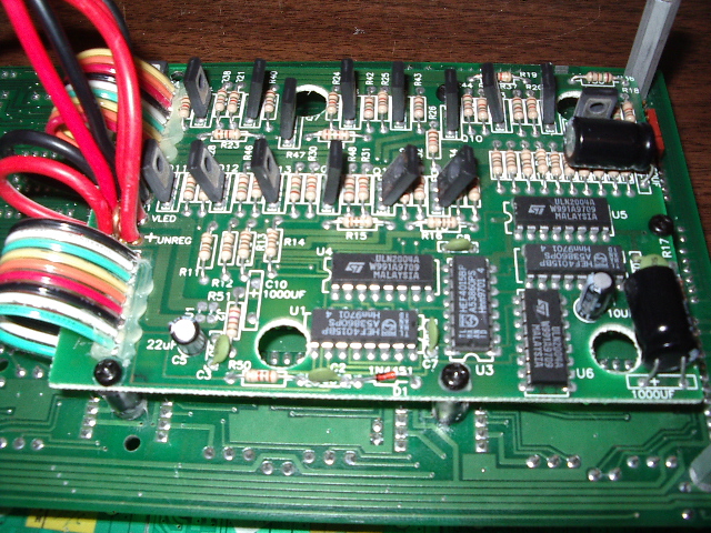
Row controller board

Here is the row driver board.  On the left are the large LED power wires going to the column driver board below.  The upright transistors are the power drivers.  Since they do not have heatsinks, the LEDs cannot stay locked on; circuitry in the row driver logic prevents this from happening.


Making it light up
The board electronics treats the matrix as 16 rows of LEDs, with 32 bi-color LEDs in each column.  Here are the six inputs available on the column driver board:

Signal name
Function
CLK1
Clock to 32 red columns (4094, pin 3).  Data is valid on rising edge.
DATA1
Data to 32 red columns (4094, pin 2).  Data is transferred to outputs on rising edge of CLK1.
CLK2
Clock to 32 green columns (4094, pin 3).  Data is valid on rising edge.
DATA2
Data to 32 green columns (4094, pin 2).  Data is transferred to outputs on rising edge of CLK2.
STRB
Store signal to both columns (4094, pin 1).  Also serves as clock signal to chain of 4015s on row driver board
OUTE
Output-enable to both columns (4094, pin 15); columns are driven when OUTE is high.  Also serves as data
signal to chain of 4015s on row driver board.

The first four signals are straightforward.  Put a 1 or 0 on DATAn, bring CLKn low, then high, and the data advances across the output pins (assuming STR and OUTE are both high).  But that only covers the column driver.  If the signals going into the row driver board aren't correct, no lights.

At this point, I needed a flexible way of trying different signals and timing.  This means a small, breadboard-friendly MCU.  So I grabbed a Teensy 3.1 and an experimenter's board.  Check my webpages on bare-metal Teensy 3.1 development for more details (here and here).

I should point out here that every input on the board is buffered by a 4049 hex inverter, so all of the inputs are inverted.  When I talk of a signal being low or high, I'm referring to the signal's state at the input of the chip on the board, which will be opposite of the state on the board's connector.

The board supports two large power supplies, labeled VREG and VLED.  According to Warren, the power supply driving the board only outputs +5 VDC.  So I wired these two rails together, then grabbed a 5 VDC, 4 Amp power brick and spliced on a suitable power connector.

The input connector has a resistor network on all inputs.  This network pulls each input to ground through a 47K resistor.  Since the board wants 5 VDC logic, I needed to convert the 3.3 VDC logic from the Teensy 3.1 outputs.  I did this by adding a 1 Kohm pullup resistor to +5 VDC (from the Teensy 3.1 VUSB terminal) to each output.  My code sets each output pin to open-drain before use.

The block of code for controlling the column driver inputs is pretty simple.  I used bit-banging to move the clock and data pins, with spin-loops between each state change to slow down the signals enough that the board would see valid data.  I used an oscilloscope to confirm that the signals at each 4094 output looked good; as I sent data into the first 4094, I could see the data walk across the whole chain of shift registers..  With the column driver code solid, it was time to tackle the hard part, the row driver logic.

The row logic requires me to use OUTE as a data line, but this line is also the output-enable for the column driver.  So I need to make sure that when I finish refreshing the display, I leave OUTE high so the LEDs actually light.

I spent a few hours getting the logic exactly right.  I could see data going into the row logic, and everything looked perfect, but the LEDs didn't light.  What was wrong?

Turns out the problem was with the 4015 master reset (MR) signal.  The board designers wanted to ensure you could not lock the display on with any error in your data or clock lines.  They added a small circuit, shown in the bottom-left corner of my schematic, that enforces this design decision.

They basically hold MR high all the time, which removes row current from the LEDs and leaves the board dark.  The only time MR goes low, which provides row current, is a brief pulse following a high-to-low transition on STRB.  This means that the STRB signal must be toggled periodically to light the LEDs.  If the display is static, all you have to do is bounce STRB now and then.  But if the display changes, STRB will toggle as you drive in the new data, which automatically lights the display briefly.

I changed the code around to refresh the display 60 times a second and was rewarded with a bright LED display.


The Game of Life
A board full of LEDs, driver code already done...time to see some Life!

If you haven't done a Game of Life yet, check Wikipedia or other web resources for details.  This is a two-dimensional visual treat, perfect for large LED matrices.  The code is simple but the effects can be pretty amazing.

My code views the 16x32 matrix as a wrapped world; cells that move above the top row reappear on the bottom row, and cells that leave the left side appear on the right side.

The matrix is small enough and the Teensy 3.1 is fast enough that I calc a new generation 30 times a second.  This is too fast to see most of the low-level action, but the automata seem alive as they flit across the board.

Here is an MP4 showing about 20 seconds of Life (it takes a few seconds before the action starts).  The Life display is updated at the rate of 30 generations per second, so this short clip shows several hundred generations.

Here is the source code for my Game of Life.  This code includes all of the driver logic plus a simple menu of commands that I can enter from the console (TeraTerm hooked to UART2 on the Teensy 3.1).  The code is for reference only.  If you were to try and rebuild, you would need a lot of my library code, for modules such as the UARTs, terminal I/O, and others.

Unless you are a close friend of my buddy, Warren, the odds of you actually getting one of these boards is slim.  But this page is about the journey, figuring out how a random piece of old electronics works, then proving you've sussed it right by making it do your bidding.  It's a lot of fun and a great learning experience.


Home