Teardown of a Greenlite 8W LED light bulb
(Last modified
15 Jul 2012)
On a recent trip to a local hardware store, I saw a stack of Greenlite
120 VAC LED lightbulbs, marked at $6 for a box of two bulbs. The
package clained the bulbs provide 450 lumens, which was advertised as
the equivalent of 40W bulbs; plus, the bulbs are dimmable.
Naturally I had to pick up a few. Naturally, I also had to tear
some apart.
Before I start with the teardown, I should mention that these bulbs are
brighter than I expected and work well with a dimmer. I replaced
some 60W frosted incandescents with these LED bulbs, in my office
ceiling light fixture. The LED bulbs' light is as bright
(subjective, I know) as the original bulbs and I like the 3000K
temperature better. Since they are LEDs, they produce far less
heat than the original incandescents, which helps in the summer.
First, the warnings!
This teardown involves breaking the bulb's glass and working with
exposed broken glass. Wear eye protection and work
carefully. The bulbs contain some totally excellent LEDs, but
they aren't worth making mistakes or taking shortcuts and injuring
yourself. The instructions below worked for me, but you are on
your own for this teardown!
I started by using a pair of slip-joint pliers to crush the bulb's
base. This took considerable hand strength; get some help if you
need it. Another option might be to clamp the screw base into a
bench vise and crush it with the vise. My goal here is to crack
the screw base enough to free it from the plastic frame it is mounted
on. Note that I only applied enough strength to crack the seal
between the metal wrap (the part with the screw threads) and the
plastic frame above it.
With the screw base cracked free of the plastic frame, I used a spare
pair of wire cutters to slice away the plastic frame so I could remove
the screw base. There is a small section of PCB that sits inside
the screw base and has two small wires connected to the metal parts of
the screw base, one to the tip of the base and one to the metal
wrap. I simply tore these two connections off when I removed the
screw base.
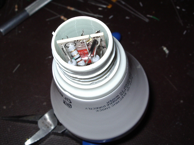
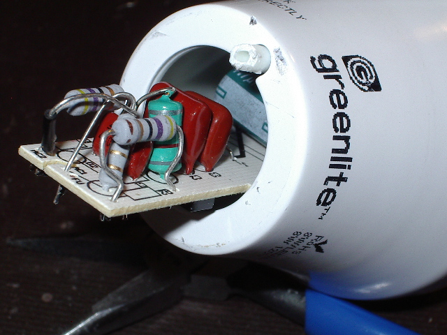
Here is the bulb with its screw base removed. You can see the
narrow end of the PCB with some power resistors on it.
Next, I put the bulb in a heavy plastic freezer bag, then tapped the
glass bulb with a hammer to shatter the glass. I was careful to
use the least amount of pressure needed, since the LED array is just
underneath the glass and I didn't want to damage that.
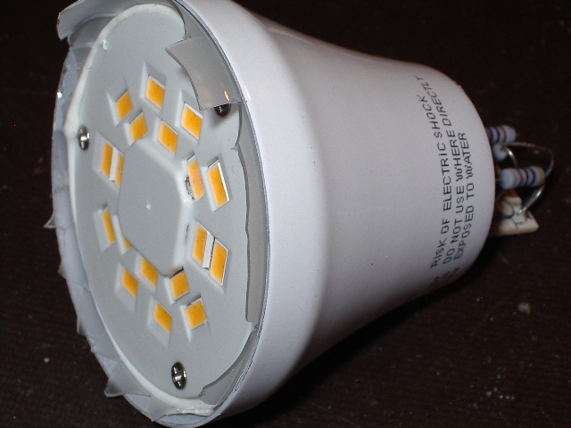
Here you can see the top surface of the LED array. There are 18
very large LEDs mounted onto a PCB underneath the white plastic shield
you see here.
I used a thin blade screwdriver and a hobby knife to remove the glass
shards. The glass is embedded in a silicone rubber compound that
seals the white plastic shield to the glass and to the bulb's metal
frame. I worked carefully on this phase to avoid injury while
removing the glass.
With the glass and sealing compound removed, I removed the three screws
you see above. This freed the white plastic shield, exposing the
LEDs and the PCB they are mounted on.
Here is a closeup of the LEDs on their white PCB. Note that the
PCB floats on a thin film of silver thermal compound, held in place
only by the tension of the red and black power wires you see in the
center of the PCB. You can see some of the leftover sealing
compound on the outer rim of the metal platform below the PCB; this
metal platform acts as the LEDs' heatsink.
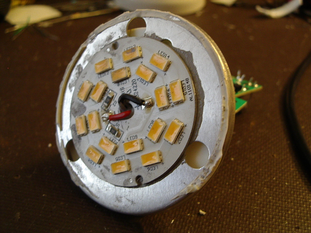
Here you see the LED PCB after some handling, as I was tracing out the
circuitry. The dark grey smudges are some of the heatsink
compound that I spread while handling the PCB.
Note that the black wire is soldered to a pad marked with a plus-sign
and the red wire is soldered to a pad with a minus-sign (between two
zero-ohm resistors). I verified with a DVM that the markings on
the PCB are correct; the pad marked with a plus-sign is connected to
the anode of the first LED in each string.
The LEDs are wired as two nine-LED strings; one string is LED1 through
LED9 and the other string is LED10 through LED18.
Summary
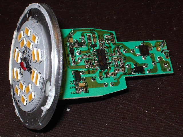
So I now have a small PCB, about 1.5" across, with 8
watts worth of very bright LEDs to play with. It will be simple
to repackage the PCB as a spotlight, garden light, or as a giant pixel
in a really big sign or art project. It would also be easy to
harvest the individual LEDs for use in smaller projects. Total
cost for two PCBs and 36 LEDs, six dollars and a bit of work on my
part. By the way, there are some pretty nice parts on the driver
PCB that are also worth harvesting.
Home