(Last modified 2 January 2017)
This project (sdlocker1k) is my entry in the Hackaday 1K Challenge, which ended in January 2017. My goal was to cram a tool that can write-lock or password-lock an SD card into just 1k bytes of code on an Atmel MCU.
For background information on this project, please see also my other web pages on SD card locking, SD Locker and SD Locker 2.
Please note, I did not meet my original goal of having BOTH write-lock and password-lock in the same executable. This project can fit either feature in less than 1K, but not both. You can easily rebuild to include both features, but the code weighs in at about 1102 bytes; not bad, just a tad too big for the challenge.

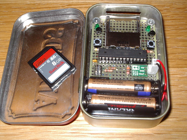
Above is the SD locker 1K, fitted into an Altoids tin. You can see a tiny 3.3 VDC up-verter (green and white PCB) just above the AAA battery holder. The pushbuttons control write-lock (left side) and password-lock (right-side). Just above each switch is the corresponding transistor driver and LED, which show the current state of each feature.

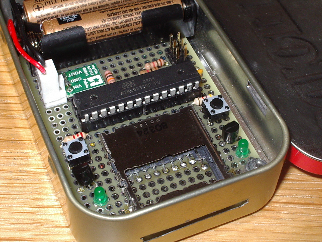
Above is a closer view of the electronics. The six-pin connector just above the MCU is for the programming pod. I used an AVRISP mkII, but you can rewire this connector (if needed) to support whatever you use.
The hardware
I built the sdlocker1k around an Atmel ATmega328P. A chip of this size, with 32K of flash, is overkill for the final executable, but in the early stages of development, I used the on-chip UART for debugging and needed more code space to hold that added code. Besides, it was near the top of the pile in my parts bin. :-)
The design includes two pushbutton switches and two associated LEDs. One switch controls the write-lock feature. With an SD card inserted in the device, pushing the write-lock switch toggles the write-protection feature (the TMP_WRITE_PROTECT bit in the card's CSD register). The current state of this bit is reflected in the write-protection LED; the LED is lit if the SD card is write-protected.
The second switch and associated LED support the password-lock feature. Pusing the password-lock switch toggles the password-protection feature (using CMD42). The current state of this password lock is reflected in the password-protection LED; the LED is lit if the SD card is password-protected.
The original challenge only concerned code size, but I tried to use the smallest possible hardware, as well. The LEDs are tied to the '328's MOSI and SCK lines, rather than using separate GPIO lines. This provides two benefits. The LEDs flicker as data are exchanged between the MCU and the SD card, and the dual-use reduces pin count. Likewise, the two pushbutton switches are tied to a single A/D input through a simple resistor network, which saves another I/O line. Total I/O requirements, including support for the Atmel programming connector, is only six pins.
This small pin count means the project should fit in an 8-pin MCU. I tried porting this to an ATtiny13. The code fit, but the 'tiny13 does not have a hardware SPI port, and the bit-banged solution was too slow to be useful. However, this code, with minor tweaks, should run fine in any 8-pin MCU with hardware SPI (or at least hardware synchronous serial I/O).
Another hardware goal was to fit this into an Altoids can (duh!). My original SD locker used AA batteries for a power source, but that took up too much room and was overkill for the minimal amount of power this circuit needs, so I scaled back to two AAA batteries.
As with the original SD locker, I used a tiny Pololu 3.3 VDC up-verter to generate a stable voltage for the SD card; note that this addition is not shown in the schematic. I wired the AAA batteries in series with the card-present switch in the SD card holder, so power is turned on when you insert an SD card.
Here is the schematic (PDF).
The firmware
I started with the software from my sdlocker2 project, then began slashing and recoding. My development suite consists of the avr8-gcc compilation suite paired with Visual C 2010 Express as an IDE. I build using custom makefiles and custom linker scripts. The linker script is a modified version of the stock flash linker script that ships with avr8-gcc. I'm pretty sure my source files will build properly if used in an AVRStudio environment, but I haven't tried it.
(Please don't email me asking about doing this project on Arduino. I don't do Arduino, nor do I have any intention of ever doing Arduino. And if you want to become proficient in the firmware arena where time and space matter, I suggest you start working on bare-metal embedded firmware. This project would make an excellent starting point.)
I added the ability to compile variations of this code. The options depend on two #defines, at least one of which must appear, either at the top of the source file or in the compiler invocation.
If you #define the literal BUILD_WRT_LOCKER, the compiler will generate code that can write-lock and write-unlock your SD card. In this version, the password-lock button does nothing.
If you #define the literal BUILD_PWD_LOCKER, the compiler will generate code that can password-lock and password-unlock your SD card. In this version, the write-lock button does nothing.
If you #define both of these literals, the compiler will generate code that supports both features.
Here is the final result:
| #defines | Code size | Functionalty |
| BUILD_WRT_LOCKED | 926 bytes | write lock/unlock |
| BUILD_PWD_LOCKED | 960 bytes | password lock/unlock |
| BUILD_WRT_LOCKED and BUILD_PWD_LOCKED | 1102 bytes | write and password lock/unlock |
The password used is hard-coded in the source file. You can edit the source to change this password; just follow the same format you see in my file.
Code compression
One of the first steps in code trimming was to remove as many global variables as possible; the final code cut this down to 20 bytes of RAM. This saved several bytes of code space and was a good start.
Next up was eliminating the startup code. This is a block of code prepended by the linker during the build process. It consists of two main sections. The first section is the vector table, used by any interrupt service routines (ISRs) your project has. Since this code has no ISRs, I certainly didn't need to waste the code space for a vector table.
The second section of startup code initializes any global variables in your program. If your program initializes variables before use, or if your code doesn't care about initial values, this section of startup code is wasted space and can go.
I addressed the vector table issue by making my own startup routine, in a file named start_m328p.s. Here is the entire file:
.section .vectors,"ax",@progbits
.global __vectors
.func __vectors
__vectors:
;
; No need to clear SREG (0x3f) as its reset state is 0.
; No need to set SPL and SPH, as their initial states
; are RAMEND.
;
eor r1, r1 ; C wants R1 to hold 0 always!
jmp main ; jump to top of constructor inits
.endfunc
The only two lines of code force R1 to hold a value of 0, as assumed by the C compiler, followed by a jump to main(). The linker will place this code at address 0, which is normally the reset vector. Rebuilding with this startup file removed the vector table but the linker persisted in adding the variable initialization code.
To remove the variable initialization code, I assigned my few remaining global variables to the .noinit section. This tells the linker that these variables do not need to be initialized before use. Here is the code that performs that placement:
/*
* Global variables
*
* Assign all global variables to the .noinit section. This means the linker
* will not add initialization code to zero these variables. This also means
* your code can NOT assume a global variable has been cleared before use!
*/
uint8_t csd[16] __attribute__ ((section(".noninit")));
uint8_t cardstatus[2] __attribute__ ((section(".noninit")));
uint8_t pwdswcount __attribute__ ((section(".noninit")));
uint8_t wrtswcount __attribute__ ((section(".noninit")));
With this change in place, all of the linker-included initialization code disappeared. The overalll savings was more than 100 bytes, which is a big gain where every byte counts.
I also "unfactored" some of the code, removing modules of code and in-lining them when they were only invoked once. Writing code in modules is a good practice in general; it helps readability and lets you build your design in stages. But in some cases, such as writing for tight space limits, modular code needs to be questioned. Each subroutine involves several bytes of hidden stack preparation and teardown. If the module is only called in one place, consider copying the entire module into the calling routine to eliminate the stack code. Doing this saved another few dozen bytes of code space.
My original code did a lot of status checks and error reporting. This was driven partly by access to a UART for error logging, and partly by the experimental nature of that first project. For this project, however, there was no need for UART support. For error status, the user can just look at the LEDs; if they are not in the expected state, something is wrong and you have to try again. These assumptions let me pull out all the error checking code. It also let me recode routines that used to provide a status value to now be of type void. These changes whittled off another several dozen bytes of code.
(Obviously, I am not recommending your projects abandon status checks or error reporting. However, you should evaluate their necessity. In this project, they don't contribute enough to warrant the extra space they consume. YMMV.)
Finally, this code also removes use of the CRC-7 check values. When sending small commands and data blocks to an SD card, your code is expected to append a 7-bit CRC value, formatted so the CRC is in bits 7 through 1, and bit 0 is set. My tests showed that my SD card (a SanDisk 8GB) was perfectly happy with a dummy CRC, provided bit 0 was set. This meant I could drop the CRC generator, saving more precious bytes. I have tested this CRC-less code on a few SD cards of various brands laying around the house, and all cards behave as expected, but I will admit to a bit of nervousness about removing such a crucial guard.
The final result
Here are a zip file containing the source code and hex files for this project. I provide three hex files, for those who just want to blow this code into a 'mega328p and get on with it. I also include my makefile and linker script, which should help those of you working with other build chains.
This was a fun project, and it was good to revisit my SD locker projects. My thanks to Hackaday for a great challenge, and for dragging me away from Path of Exile to accomplish something (more) useful.
Please drop me an email with any comments or suggestions.
Home