Hacking a plug-in timer for battery
operation
(Last modified
15 Feb 12)
I needed a battery-operated timer for an LED project, but all I
could find at the local hardware store were the cheap, plug-in-the-wall
timers for AC appliances. Except for the AC power, the timer had
everything I needed; LCD screen, lots of programmable features, RTC
built in. So I took a couple of them home to see what I could
make from them.
The device I chose is a Westek 1-Outlet Digital Timer with 20 (!)
programmable on/off events per week (not that I'll ever use that
many). Check the pictures below for details.
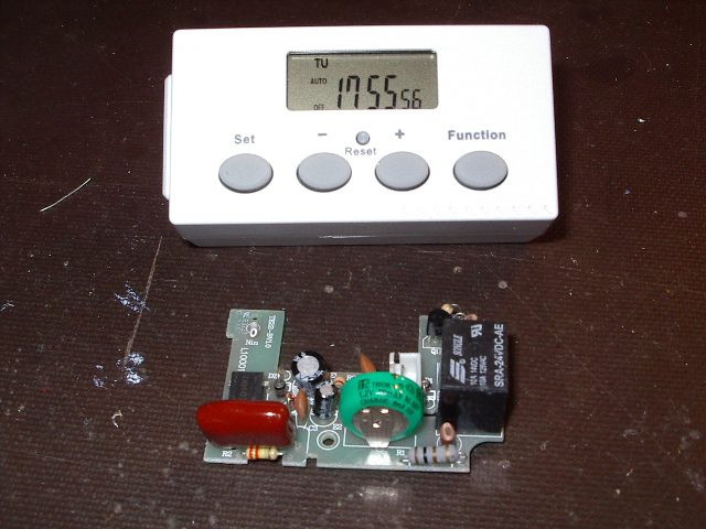
Here is a new, unopened timer, alongside the guts from the timer I did
this hack on. Notice that the timer is running, even though it is
unplugged from the mains. The timer is being powered by an 80
mAH, 1.2 V NiMH battery (green and silver disc on the PCB).
Circuitry on the PCB will recharge the battery any time the device is
plugged into an outlet. Since the timer probably hasn't been
connected to mains in weeks, you can see the timer and display
electronics draw very little power.
The black cube on the right end of the PCB is a 24 VDC relay that
switches mains power to whatever is plugged into the timer. This
relay in turn is switched on/off by a transistor (hidden by the
battery).
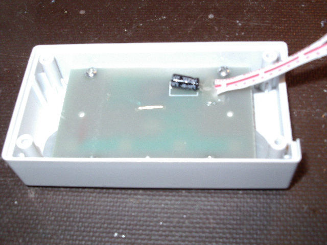
Here is the backside of the display board. The three white wires
provide GND, 1.2 VDC, and an output from the board that controls the
transistor mentioned in the above paragraph. This output is 0 VDC
to turn the relay off and 1.2 VDC to turn the relay on.
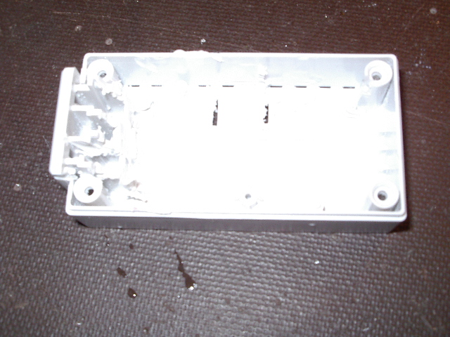
In this photo, I've taken a Dremel tool to the inside of the case that
originally held the power PCB. I've removed all of the molded
plastic that held the PCB and the prongs to the AC plug, leaving a gap
large enough for a single AA battery holder.
When you use a Dremel on the case, be sure to wear a dust mask and use
good ventilation! The dust and fumes from this operation are
nasty and cannot be good for your lungs.
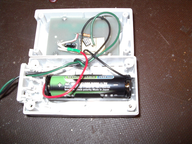
Here I've added a Radio Shack AA battery holder, a AA NiMH battery, a
PN2222 transistor, and a 1K ohm resistor. The transistor and
resistor are stuck to the back of the display board with double-sided
foam tape. The battery holder is stuck to the bottom of the case
with double-sided foam tape, as well.
The green and black wires are routed through a slot in the side of the
case that originally held one of the prongs for the AC plug. I
tied a knot in the two-wire cable to act as strain relief after the
unit is assembled.
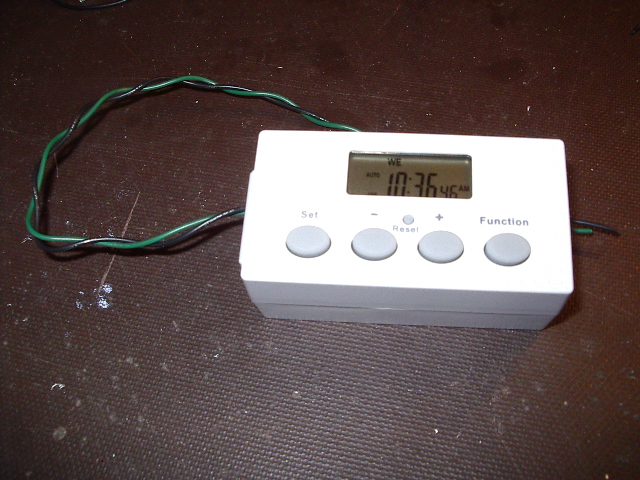
All done! I've reassembled the unit, then used the timer's
instruction sheet to set the current time and day.
The electronics
There isn't much to the electronics. Here is a schematic of the
hack:
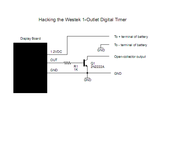
I connected the output wire from the display board (middle wire in the
group) to one end of a 1K ohm resistor, then hooked the other end of
the resistor to the base of a PN2222 NPN transistor. (Yes, the
schematic shows 2N2222A; either will work.) I hooked the ground
wire from the display (near the negative lead of the small electrolytic
cap on the back of the display board) to the emitter of the
transistor. I hooked the positive wire from the display (near the
positive lead of the cap) to the red lead from the battery
holder. Finally, I hooked the black lead from the battery holder
to the ground wire from the display.
At this point, I plugged in a AA battery and the timer's display lit up
and started tracking the time.
With the battery unplugged, I hooked a long black wire to the ground
wire from the display. I also connected a long green wire to the
collector of the PN2222 transistor. These green and black wires
are the control output from my hacked timer; I routed them outside the
case through one of the slots left over from the AC power plug. I
reinstalled the battery, put the electronics back in the case, closed
it up, and I'm done!
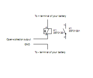
To use this device as a battery-powered timer, you will need to think
of it as a 555 timer, but fancier. The 555 timer has an
open-collector output on pin 3; this modified timer also has an
open-collector output (the green wire). To control a load, you
need to hook the negative lead of your load (say, a relay) to the green
output wire and hook the positive lead of your load to an external
power supply, such as a battery or solar panel. Then hook the
negative lead of your power supply to the black ground wire. Like
this:
Next, use the timer to turn the load on or off. As a quick test,
you can use the front-panel buttons to step through the options until
you see ON blinking. If you then press the SET button, the load
will come on. Now step through the options again until you see
OFF blinking. Press SET and the load will switch off.
Options
You may not be able to get exactly this model, so
you will probably have to use these instructions as a general
guide. I suspect that if you can find a timer that is running
while in its blister pack on the store's wall, you should be able to
make this hack work.
The PN2222 transistor can be just about any NPN switching
transistor. Be sure to check the data sheet for your transistor,
to get the correct leads for emitter, base, and collector. If you
hold a PN2222 transistor so the leads are pointing down and the flat
side of the transistor is facing you, the leads (left to right) are
emitter, base, and collector.
The original 80 mAH battery was recharged from the mains whenever the
timer was plugged into the wall. The AA battery I used here will
basically get shelf life (up to three years for the low self discharge
NiMH batteries). However, if you want to make sure the battery
"never" runs down, you can add a small solar panel battery charger to
the unit.
To add a solar charger, bring out a separate ground lead (same
connection point as the black wire in the output cable) and a red wire
that is hooked to the red wire of the AA battery holder. You can
treat these two wires as if they were a NiMH battery that you want to
hook to a solar panel charger. Be sure that the voltage applied
to these wires never exceeds 1.4 VDC. Additionally, provide some
kind of protection against overcharging the battery; limit the current
to no more than C/10, where C is the discharge capacity of the battery
(2600 mAHr, in my case). Finally, be sure to include a blocking
diode between the solar panel and the battery connection, to keep the
solar panel from draining the battery when the panel is in the
dark. For excellent discussions on solar panel battery chargers,
check this
page and this
page.
Although I show a NiMH battery here, you could also modify this circuit
to use a solar-charged supercap. You would need to replace the
battery with the appropriate supercap and add a suitable charging
panel, but you would end up with a timer that would basically run
forever.
I can see this timer being used to control all kinds of low-voltage
projects, such as LED garden displays and artwork, remotely located
data loggers, or long-term photo equipment. In particular, you
can control Arduino (or other MCU) projects that don't have a built-in
real-time clock but need to wake up now and then, on a schedule, and
perform some action.
If you try this project, please drop me an email. I'd like to
hear what other timers work for this hack.
Home


