![]()
![]()
![]()
![]()
![]()
![]()
![]()
![]()
![]()


All my content and ptohos

Atari Mega 1
A professional version of Atari's 16-bit computer was
called Mega. In its typical form, it was in a small desktop ("pizza
box") casing, with detachable keyboard. As 1040, the Mega 1 had 1MB of
RAM, a 68000 CPU runing at 8MHz and Atari TOS system in ROM with
possibility to load extensions from floppy at start-up. The primary
difference, except casing, was addition of a BLITTER chip - a special
co-processor for moving and copying specified areas of memory very fast.
These operations are needed when processing images. Additionally, the
computer had a battery-powered RTC with nonvolatime data region as well
as additional time-of-day clock built in keyboard firmware. The
keyboard, mouse and joystick controller was built-in detachable
keyboard, connected with a 6-wired cable (serial port). There was also
an internal bus for attaching expansion boards.
These computers were popular in Germany in applications which required
colour graphics processing. 1MB of RAM gave it much power and disk
compatibility with PC made it chosen in multi-computer environments more
frequently than Amiga.
| Manufacturer | Atari |
|
| Origin | USA | |
| Year of unit | 1989 | |
| Year of introduction | 1987 | |
| End of production | 199? | |
| CPU | Motorola MC 68000 | |
| Speed | 8MHz | |
| RAM | 1024kB | |
| ROM | 256kB (TOS) | |
| Colors: | 512 | |
| Sound: | YM2149 chip, MIDI | |
| OS: | TOS in ROM or from floppy | |
| Display modes: | Text: 40/80x25
simulated Graphics: 320x200x16, 640x200x4, 640x400x2 (special monitor needed) |
|
| Media: |
Built-in 3.5" FDD (1040STf) External 3.5" FDD Optional external HDD. |
|
|
Power supply:
Additional Peripherals: |
||
| I/O: | Serial port (RS232) Centronics Hard disk port (dedicated) Ext. floppy disk RGB Keyboard, Joystick, Mouse Cartridge expansion MIDI ports |
|
| Possible upgrades: | Memory upgrades, HW mods, commercial expansions | |
| Software accessibility: | Quite easy (TOSEC, old sites) | |
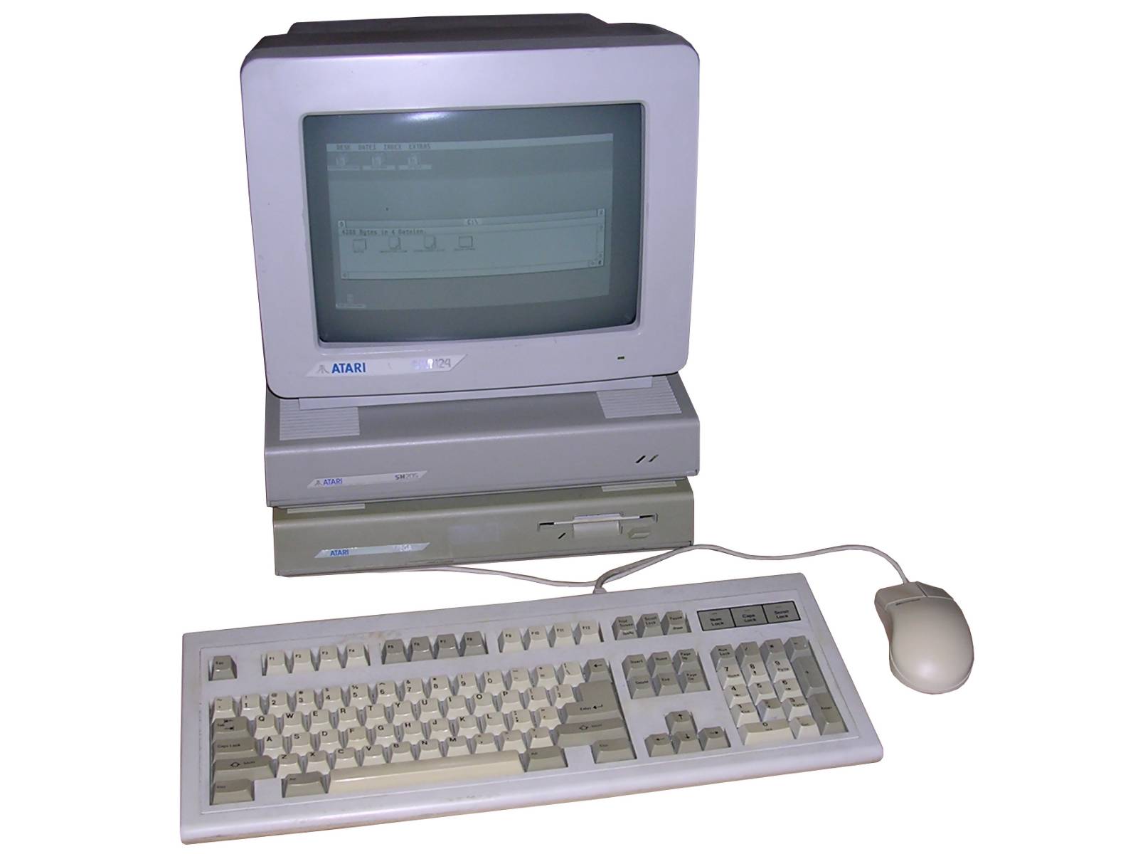
My unit is from Germany. Not much more can be told about it. I got it without keyboard or mouse and had to make one using PS/2 PC peripherals and Arduino chip. It was a "cost-reduced" unit, without fan and with quite poor PSU technology, but with early mainboard with 6 ROM spaces (2 chips used). Additionally RAM has been soldered not a very good way, with skewed chips.
| Contents: | Starting | ROMs | Pinouts | Keyboard | Hard disk | Links |
Starting
If you have a hard disk connected, power it on before
and wait until it spins up.
Mega will also start for a quite long time with gray/white screen
looking for things in a non-existing floppy disk. If the floppy drive is
OK, just give it any720K floppy disk, may be a PC disk formatted to
720kB. With disk in drive it'll start more quickly.
If external hard disk is connected, it'll read a driver called AHDI from
it.
Information about making system disks and starting ST in
smaller Atari ST page.
If you have a hard disk, remember to park its heads it you plan to move
it around. The Atari's method is to launch SHIP.PRG program from a
floppy, not from disk, as returning to system would make another read
from no-parked HDD to display its windows back. If you don't want
parking from floppy, there is a N_SHIP program attached with my AHDI
programs set, this one closes HDD windows before parking heads.
ROMS
There are numerous configurations of ROMs, for 192kB TOS or 256kB. If there are 2 chips, it's usually a 256kB TOS, and it can be upgraded easily. If there are 6 circuits, they're usually 32kB ROMs for 192kB TOS. Usually ROMs from the net come with IMG files which are dumped (concatenated from all ROMs).
To restore them to "flashable" form, you have to split
it. This will cover situation with TWO chips (they're 128kB each):
- Split the IMG file separating EVEN and ODD bytes to HIGH and LOW
parts.
- Round resulting parts to 128kB filling them with 0xFF (faster EPROM
programming).
To update TOS with EPROMs, it may be needed to make adapter for
inserting an EPROM into a ROM socket. For a 256kB TOS (2x128) you need a
27C001, 011, 1001 or similar 128kx8 EPROMs. The pinouts of ROMs can be
found in TOS104UP.ZIP document (see "More files" button).
I tried to run 4 TOSes: 1.04 German, 1.04 English (and they worked from
27C004!) as well as English 2.06 and 2.06 Polish, these 2.06 didn't work
even when I was sure that W2/W3 jmpers were properly set (setting them
to 2/3 makes pins 1 and 22 accordingly A15 and A16).
However, if you need multiple TOSes, for example, one for your language
and one "original", you can make a switch using two 512kB EPROMs (e.g.
27C004).
The switch is described in 4tos_swc.zip document (see "More files").
However, installation of this switch requires you to have EPROM adapters
I wrote about. Summing up, you need to accordingly switch address
address lines to high/low states, and in both chips they should have the
same state.
The physical space is quite limited between chips. If you cram two
pull-up resistors in adapters, it will require only 3 wires to switches:
One from ground and two from resistor-EPROM pins connections. The
resistors are only to have high on pins if nothing is connected there,
so the switches can be open-close switches instead of pin toggle ones.
You need two switches to switch TOS versions. How to install them
without damaging the casing? Use vent holes!
To prepare ROMs for such module, just concatenate all 128kB HIGH ROMs to
one file and LOW to another in the same order, then flash them into
chips.
Pinouts
See Small Atari ST page.
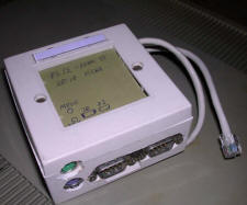
Keyboard
| This is a different topic. The keyboard, connected with
RS232 at TTL levels, has quite significant intelligence inside.
Currently (2017) it may be hard to get keyboard, so a PC
keyboard and mouse may be used with help of a microcontroller
translating protocols and emulating non-existing devices. There is a probably complete solution called Eiffel, to connect PS2 keyboard and mouse, as well as joysticks, to ST but it requires microcontroller not easily available today. The PIC16F876A is accessible more easily, but will NOT work as its flash memory procedures are different. As a quick solution I tried to implement another PS/2 - ikbd translator using Arduino platform with ATMega328 chip which is, and for a few years probably will be, better accessible. It is on its own hacks page. The problem is that it is not tested extensively - default, power-on mouse, keyboard and joystick settings seem to work. |
 |
|
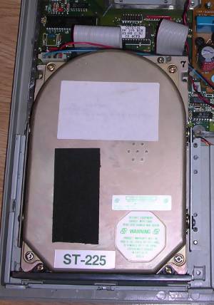
The SH205 hard disk is an unit connected with ACSI - a
reduced SCSI mutation used by Atari. It requires 19-pin
connectors (DB19) connected 1:1 (computer to HDD's IN
connector!), if they're not accessible, you can make one by
removing 6 pins from 25-pin connectors, remove them on one side
and it may even connect without grinding down part of casing. InternalsThe SW1 triple DIP switch is used to enable
secondary data channel (by turning them OFF) on MFM interface,
so having a connector installed in you can theoretically (or
practically - see
this in German) install TWO drives. I have no idea how they
may fit well without getting too warm. Usually this switch is
protected some way, it may be covered with transparent tape seal
or filed flat not to make user accidentally switch it. |
 |
The jumper J8 has the following positions: T,S,R and PU and
is repsonsible for write precompensation signal generation. It is possible
to connect:
- S to R
- T to R
- PU to R.
The R is a control of write precompensation enable line in AIC-250 chip (see
its documentation). It is usually tied to Write Gate. Selecting T makes
it AND-dependent on a CPU READY signal (usually is high). S makes it
AND-dependent on Reduced write current signal generated by 8156. PU totally
forces the line on LOW. According to notes on the SH204 schematic, The R-S
position (dependent on RWC) goes when ST225 drive is used and R-PU (force
line low) when Tandon TM262. See
schematic , page 12.
Excerpt from technical notes, but I think not all ROM revisions may have it
(my unit doesn't go with it and is 100% OK!):
SELF DIAGNOSTICS TEST
NOTE:
These self-diagnostics are for troubleshooting on a system-level only. They
are not intended for repair of the board.
The ACB-4000 Series Controller has built-in diagnostics. These are performed
at power-on time when the O-P jumper is installed. DO NOT connect the
cables. If the board is functioning properly the LED will flash conitnuously
with duration of 0.5 - 1.0 secondd per flash. If there is a problem with the
controller, the LED will stay on for 6 seconds, flash once for one second
(notating the start of diagnostics), and then flash in 0.5-second bursts.
This will then be repeated as long as the O-P jumpoer is installed. The
number of 0.5 second bursts is the error code. The error codes are detailed
in below table:
ACB-4000 SERIES CONTROLLER SELF-DIAGNOSTICS
ERROR CODE (number of 0.5-second bursts) - PROBABLE PROBLEM AREA
NONE - 8085 SUBSYSTEM
1 - 8156 RAM
2 - FIRMWARE
3 - AIC-010 AND RELATED LOGIC
4 - AIC-010 AND RELATED LOGIC
5 - AIC-300 AND RELATED LOGIC
6 - AIC-010 BUS
CONTINUOUS BURSTS OF 1SEC, 1SEC, 1/2SEC (WITHOUT 6 SECOND FLASH AND 1 SECOND
FLASH) - CONTROLLER PASSES SELF-DIAGNOSTICS
When a known good drive is correctly connected to the controller, it sill
seek and read. Error codes are invalid in this mode.
ACSI Pinout:
|
|
|
| 1 - D0 2 - D1 3 - D2 4 - D3 5 - D4 6 - D5 7 - D6 8 - D7 9 - /CS 10 - IRQ |
11 - GND 12 - /RST 13 - GND 14 - ACK 15 - GND 16 - A1 17 - GND 18 - R/W 19 - REQ |
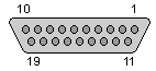
The 19-pin male connectors are hard to get nowadays. You can use 25-pin connectors. It is possible to re-make this connector by removing 6 pins, in 2 rows of 3. To cover the mounting screw in one side only, remove these pins on a single side of connector. For Atari Mega casing, remove the ones which will cover the rightmost mounting hole, not to cover FDD connector too much (verify it practically!).
Links
https://www.exxoshost.co.uk/atari/last/MEGAST/index.htm - Various
Mega ST boards
https://archive.org/stream/Atari_Mega_ST_Schematic_1986_Atari - Mega
ST Schematic
http://www.mega-hz.de/ATARI/ATARI%2016Bit/HARDWARE/CHIPS178/AHDI_HDX.TXT
- AHDI versions history
For software and mods, go to small Atari ST links page.