![]()
![]()
![]()
![]()
![]()
![]()
![]()
![]()
![]()


All my content and ptohos

iMac G3 233MHz (tray-loading)
The first model of Apple's iMac, another attempt to make the computer for everyone. iMac was designed to be used without computer skills required in earlier Macs. After opening the box all things needed to start were: connect keyboard, connect mouse, connect power and network, press power switch. Contrary to all earlier Macintosh computers it has no floppy disk drive. Many third-party companies offered external USB floppy drives and faster modems. Except USB and FireWire iMac was not much expandable.
It has no expansion buses nor external drive connectors except, but only in first models, the small slot in the connector compartment called "mezzanine slot". This slot, used in these units for debugging, had been reverse engineered and used by few companies, but Apple forbidden using it and all Macs with slot expansions (the most known: 3D accelerator with Voodoo 2 chip and 12MB of VRAM made by Micro Conversions and SCSI controller made by Formac) lost warranty.
There were 4 revisions of this computer: Revision A was the first Mac. Release B shipped several months after A had 6MB of VRAM and a few hardware bugfixed (especially with modem hardware). Announced in 1999, revision C macs were sold in 5 new colors, had 266MHz CPU and lacked infrared port. The last revision, D, had 333MHz CPU.
| Model No: | M4984 |
|
| Year: | 1998 | |
| Discontinued: | 1999 | |
| CPU: | PowerPC G3 233MHz | |
| RAM: | 128MB | |
| Max. RAM: | 384MB | |
| RAM Type: | 2 PC66 SODIMMs | |
| Hard disk: | 4GB IDE, 3.5" SL | |
| Floppy drives: | None | |
| Other drives: | Tray-loading 24x CD-ROM | |
| Graphics: | 1024x768x24bit (max) Depends on VRAM installed |
|
| Sound: | Stereo, built-in speakers | |
| Display: | Built-in 15" color CRT | |
| Dedicated OS: | Mac System 8.1 |
|
| Maximum OS: | Mac OS X 10.3.9 (recommended 9.2.2 or first X) |
|
| Expansions: | USB, FireWire | |
|
Peripherals in collection: Useful Links: |
||
| Connectors: | - 2 USB
connectors - 2 FireWire connectors - Microphone input (3.5mm jack) - Speaker output (3.5mm jack) - Telephone connector (modem) - Ethernet connector. Built-in infrared port. |
|
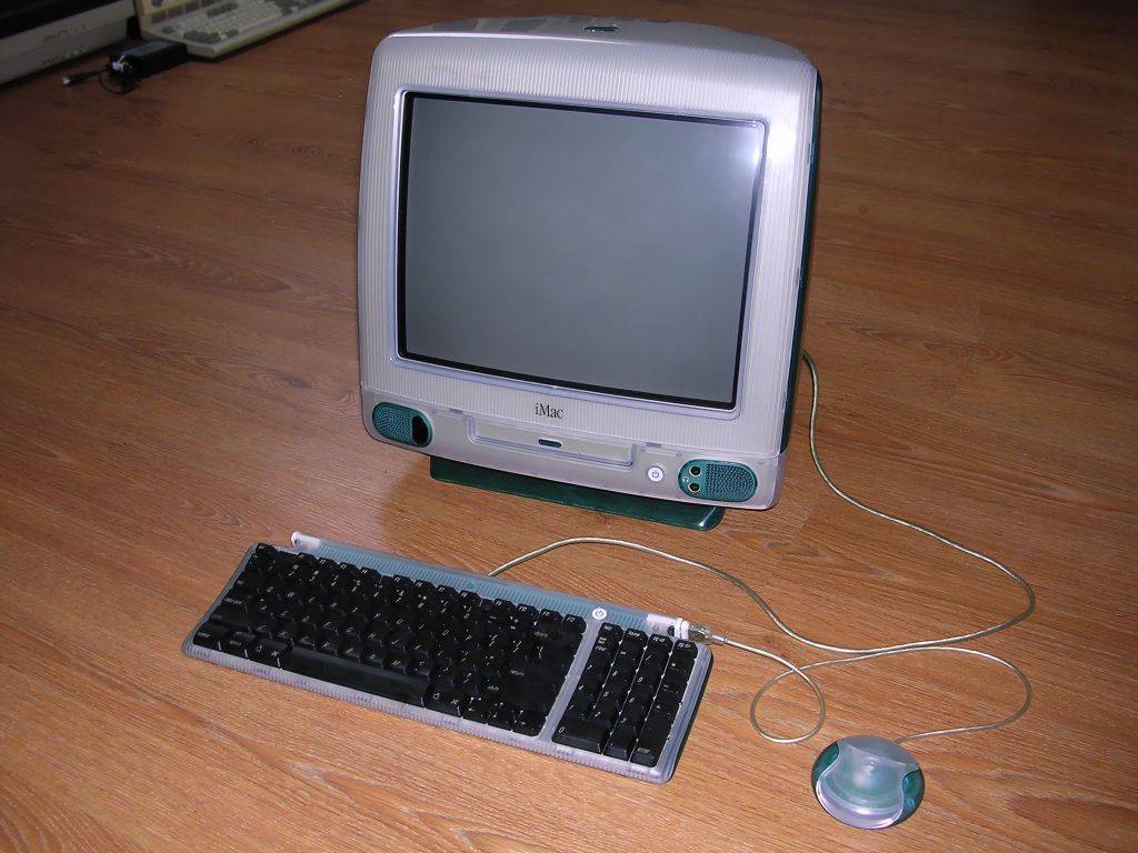
My unit comes from internet auction, but as far as I discovered it has been bought and used in some theatre in Germany. After it has been sold to Poland someone used it as text editor, replacing its strange mouse with normal Apple mouse used with later iMacs.
Here you'll find:
| Upgrading memory | Disassembly | Power & video pinout | Overclocking |
Memory upgrade
There are 2 slots in this Mac. "Big one" and "small one", allowing bigger and smaller memory modules to be plug in. You should start checking working configuration from putting larger module in bigger slot.
Mac OS 8 or 9 often see 64MB SODIMMs as 32MB. It's quite normal. More, Mac is very picky about RAM types.
If you had much luck with upgrading and successfully upgraded iMac over 256MB of RAM, you can try to run Mac OS X Tiger. It should work, but only if installed on partition smaller than 8GB, on drive larger than 8GB. Many programs won't work, as they're compiled with G4.
Disassembly procedure (not including CRT/power supply assembly).
WARNING! (and I highly recommend to take it seriously)
Disassembly of all iMac/eMac computers is hard. Generally, assembly
procedure is reverse to disassembly. But, especially on eMac it is much harder. You disassemble your Mac on yout own responsibility.
Don't blame me if you can't assemble it back!
1. Place your iMac on a soft cloth, CRT facing it. Placing Mac on screen will
give you maximum access to the logic board compartment.
2. Remove access cover. You'll se a handle and a screw in it. Remove screw and
take the handle. While keeping Mac in place with one hand (hold the colored cover of
CRT) quickly pull the handle upwards - try to do it 45 degrees from the
computer's symmetry axis. It's quite difficult to remove.
3. Remove the "main computer" - Logic board/storage chassis:
- Remove 2 screws on the top of chassis, keeping chassis (in exact its tab with 2 holes) in place.
- Remove one screw with piece of metal holding cables.
- Disconnect cables from chassis. There are 4 cables: IrDA cable (round),
Video cable (big, secured with screws), audio cable (the smallest one), and
power cable (like a little ATX).
4. Take the tab you've unscrewed in step 2 and pull the chassis upwards. It
should go nicely from the computer.
Remove the CD-ROM from the chassis
1. Place the chassis in front of you.
2. Take it by its edges and push the CD-ROM drive inwards.
3. After you feel that it's free, lift it from the chassis.
4. Remove cables form the drive.
5. To remove the front bezel you have to open drive by sticking a paperclip into
hole, remove a small screw in the bottom and release 3 tabs on te bezel.
To put it back you have to connect cables and stick the drive about 45 degree
angle. Then you can rotate it to its normal position.
CD-ROM drive in the original Bondi Blue Macs is dedicated. Using CD-ROM from later Mac (Rev. C, Five-colored iMacs) will mostly not work. CD-ROM from Bondi Blue iMac has the part number 661-2076. Model 661-2207 is compatible with five-coloured Mac. Some drives from laptops work, some don't.
Remove the hard disk
1. Remove CD-ROM, don't disconnect cables, you can tilt it on the mainboard.
2. Remove 2 screws on HDDs sides.
3. The same thing as in CD-ROM: Push it inwards, tilt by 45 degrees, slide it
out.
4. Remember that this strange piece of stiff wire on the drive is needed, as it
holds CD-ROM drive in place.
Removing CPU card:
1. Remove top RF shield from the card
2. Remove heatsink clip by prying it on one of its ends (preferred longer one)
3. Remove the heatsing by lifting it from CPU (it may go a little harder).
Consider replacing thermal grease, as it may become old.
4. Using a flat screwdriver or telephone card pry the board. Put the screwdriver
under shorter edge, closer to the RAM socket (away from CPU).
Now you can replace both RAM modules or try overclocking.
Removing mainboard from chassis (usually not needed if you don't have to
replace/fix mainboard):
1. Remove all cables from mainboard
2. Remove 5 screws from the mainboard (located in it edges)
3. Remove 2 screws holding panel securing I/O ports. Now you can remove this
panel by rotating it in tabs.
4. Lift the mainboard holding by its edges. Be careful when removing it from
power connector!.
To replace lower access cover you have to:
1. Align the bottom of cover in bottom cover cavities
2. Align and put tabs on cover's sides into cavities of the rest of iMac.
3. Remember about the screw you removed.
Power connector pinout:
It is possible to feed iMac mainboard from ATX power supply. there were even projects (warning: wire colors on this page may be wrong, in my iMac they're different!) of fitting iMac to small ATX case. All connections can be made using the following table and note:
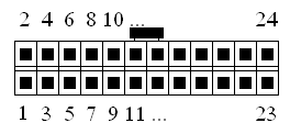
(small ATX-like female connector on iMac's power cable)
| Pin | Signal | ATX compatible |
Pin | Signal | ATX compatible |
|
| 1 | GND | GND | 2 | GND | GND | |
| 3 | GND | GND | 4 | GND | GND | |
| 5 | GND | GND | 6 | GND | GND | |
| 7 | GND | GND | 8 | 3.3V R | ||
| 9 | 5V R | 10 | 5V | 5V | ||
| 11 | 5V | 5V | 12 | 5V | 5V | |
| 13 | 5V | 5V | 14 | 5V S | ||
| 15 | 12V | 12V | 16 | 12V | 12V | |
| 17 | -12V | -12V | 18 | 3,3V | 3.3V | |
| 19 | 3,3V | 3.3V | 20 | 3,3V | 3.3V | |
| 21 | 3,3V | 3.3V | 22 | 3,3V S | ||
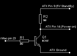
| 23 | PFW | See note 1 | 24 | T+5V | 5V StandBy |
Note 1 - This is inverted Power On signal. You have to build inverter to connect ATX to iMac:
Video pinout
The video pinout is an exact old Apple video 15-pin pinout, you can find the pinout here.
Overclocking:
Remember! This is definitely NOT factory-guaranted, so you can destroy your iMac and loose warranty! Do it on your own responsibility!
1. You should think about connecting iMac's fan directly to 12V DC (power supply connector) - as it may overheat after overclocking. On the other side connecting fan to 12V DC makes it much louder than before. To be honest, you can bump the 233's CPU to 300MHz, but it'll overheat, because on 233Mhz it works on the edge of its heat limits.
2. Disassemble: Put your iMac on a soft cloth, screen
facing it, down facing you. Remove back-bottom cover, all connectors,
remove screws holding computer assembly. Slide computer assembly up. On
the mainboard you'll see RF shielded compartment with a small board
called System module. This module contains CPU, RAM, cache and all
components needed to clock CPU. You have to remove this module (it'll be
needed to remove some heatsinks and, after disconnecting the board with
two transition connectors, rocking it in RF shield's cut-outs).
Remove RAM from it for safety. Remember only which modules were
installed in which sockets.
Now the most important thing: Flip the board to see the coprocessor and two transition connectors (to mainboard) and locate jumper resistors (0 ohm value resistors) near its edge. See this picture to find it:
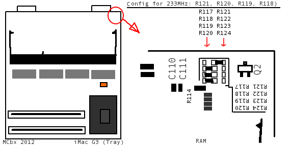
You have to carefully desolder resistors and short proper ones. Here's a complete table of frequencies:
| Clock | Multiplier | R117 | R118 | R119 | R120 | R121 | R122 | R123 | R124 | Notes |
| 233MHz | 3.5 | 0 | 1 | 1 | 1 | 1 | 0 | 0 | 0 | Like rev. A, B |
| 266MHz | 4 | 0 | 1 | 0 | 1 | 1 | 0 | 1 | 0 | Like rev. C |
| 300MHz | 4.5 | 1 | 1 | 1 | 0 | 0 | 0 | 0 | 1 | Max. for rev. A |
| 333MHz | 5 | 1 | 1 | 0 | 1 | 0 | 0 | 1 | 0 | Like rev. D |
| 366MHz | 5.5 | 1 | 0 | 0 | 1 | 0 | 1 | 1 | 0 | You shouldn't set these to this iMac! |
| 400MHz | 6 | 1 | 0 | 1 | 1 | 0 | 1 | 0 | 0 | |
| 433MHz | 6.5 | 1 | 0 | 1 | 0 | 0 | 1 | 0 | 1 | |
| 466MHz | 7 | 0 | 1 | 0 | 0 | 1 | 0 | 1 | 1 | |
| 500MHz | 7.5 | 1 | 0 | 0 | 0 | 0 | 1 | 1 | 1 | |
| 533MHz | 8 | 0 | 0 | 1 | 1 | 1 | 1 | 0 | 0 | |
| 1 - Resistor installed, 0 - No resistor. | ||||||||||
.