![]()
![]()
![]()
![]()
![]()
![]()
![]()
![]()
![]()


All my content and ptohos

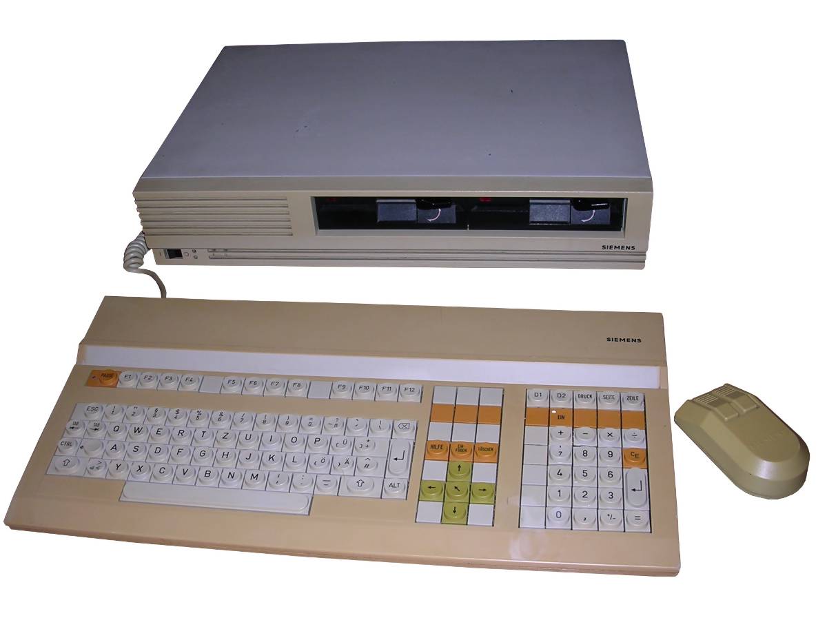
Siemens PC-D
One of the first European IBM PC-compatible (at least
in software) computers were produced by German Siemens company. First, a
PC-X station has been made, with very high-end configuration. With 80186
processor running at 8MHz, there was 1MB of RAM and 10 or 20MB hard
disk. Disk interface was SCSI, but high prices of these disks made
Siemens use converters to connect MFM drives. A special Unix-like SINIX
operating system was running on it. In 1986, two years after releasing
of PC-X, Siemens started to sell PC-D, a stripped-down version od PC-X
for home or office use. In the same time, high-end configurations for
industrial control and multi-user systems have been sold in WS or WX
line, they were PCs in casings styled like
PC-MX, but even larger.
In PC-D, mainboard has been re-designed to use MMU in flat package,
there was no NVRAM and machines usually had 256 or 512kB of RAM. Most
configurations had two 5.25" floppy disk drives and no expensive hard
disk. A specialized graphics card with proprietary monitor could output
even monochrome graphics to work with GEM environment in 640x350
resolution.
But in its hardware it was not compatible with PC at all. The system is
oriented around VG96 bus, which is purely local invention incompatible
with ISA or similarly looking British solutions (LSI). Picture is sent
to display by 25kHz composite signal. Keyboard is supported by serial
port while mouse is based on differential phase signals (my
universal one should work).
| Manufacturer | Siemens |
|
| Origin | Germany (West) | |
| Year of unit | 1986 | |
| Year of introduction | 1986 | |
| Class | XT | |
| CPU | Intel 80186 | |
| Speed | 8MHz | |
| RAM | 256kB | |
| ROM | BIOS, monitor | |
| Graphics | Proprietary, 640x350 mono, 80x24 text | |
| Sound | PC Speaker | |
| System expansion bus | VG96 local bus | |
| Floppy/removable media drives | 2x 5.25" floppy disk drives. | |
|
|
||
|
|
||
| Hard disk: | Not present, possible upgrade with SCSI drive or converter card. By default NEC D5126 (20MB) or BASF 6188 (10MB). |
|
|
|
||
|
Peripherals in collection: |
||
| Other cards:
|
None, 2 additional slots present. | |
| Non-standard expansions: | Possible to add memory up to 1MB, SCSI hard disk? | |
| Operating system(s): | MS-DOS 2.1 |
The history of my unit is not known. It was sold to me
as "floppy disk drive for Siemens WX-10 or WS-10", so probably it was
used as terminal. Keyboard and incomplete mouse are from different sets.
As it came, the machine had 2 RAM chips defective. It was repaired and
awaits a working monitor.
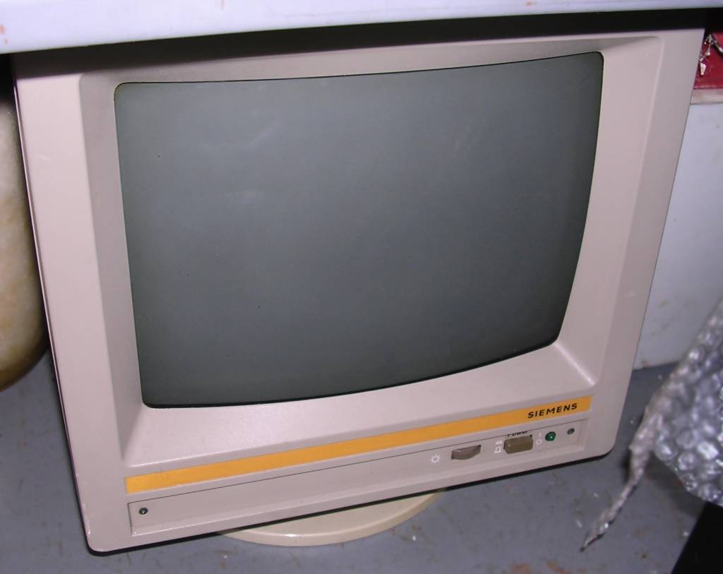
I got also a monitor but for Siemens WX/WS line, so it's colour one and
it's in quite miserable condition - converter doesn't start and
deflection are bad. Here is the photo of it, if
you want.
| Contents: | Starting, diagnostics | DIP Switches | Pinouts | Links |
Starting
After successful POST it shows:
* * * TEST END * * *
And starts to look for boot disk in drive 1 (usually one in the right), then Drive 2, if there is a hard disk then it tries to boot from it. If there is no bootable disk in drive and no hard disk to boot from, then it waits about 5 seconds and retries procedure.
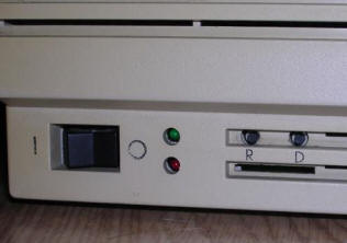
| Diagnostics: The machine starts as most PCs, preforming power-on self test called PUP (Power-Up Prufung?). This test is performed before display is initialized. After the most important tests, red LED in front panel is turned off. In front panel, there is a row of 8 diagnostic LEDs on the right of Power/Disk LEDs, below Reset/Debug buttons. You can see it in the photo as a long slot under "R D" markings. These LEDs light up in combinations when particular test ends. Service manual gives the following errors:
|
 |
| Code | LED state | Description |
| - | (*)******- | Microprocessor did not even performed Reset. Does it work at all? Applies also if all LEDs are lit up. |
| 0 | (*)------- | EPROM checksum error |
| 1 | (*)*------ | Error in first 64kB of memory while testing data lines |
| 2 | (*)-*----- | Error in first 64kB of memory while testing Address and bank switching. |
| 3 | (*)**----- | Local bus or both interrupt controllers bad (test during Read/Write IMR) |
| 4 | (*)--*---- | One or more Interrupt controllers bad |
| 5 | (*)*-*---- | Programmable timer 0 bad |
| 6 | (*)-**---- | Programmable timer 1 or 2 bad |
| 7 | (*)***---- | NMI because of access error (read of not existing I/O address) |
| 8 | (*)---*--- | Status register contents bad, NMI not ran properly? |
| 9 | (*)*--*--- | Memory test fail, preformed from 64k to the end or except last 64kB if 1MB is installed. |
| A | (*)-*-*--- | MMU Error |
| B | (*)**-*--- | DMA controller error |
| C | (*)--**--- | Floppy disk controller error |
| - | (*)*-**--- | Error detecting USARTs |
| - | (*)-***--- | Error detecting video board |
Now, 3 USARTs and video controller are tested. If there is an error in these tests, it is indicated by BLINKING LEDs, and there may be more than 1 error indicated:
| LED State | Description |
| (*)*------ | USART1 (Printer port) error |
| (*)-*----- | USART2 (Keyboard port) error |
| (*)--*---- | USART3 (Serial port) error |
| (*)---*--- | Video controller error (expansion board) |
| (*)----*-- | NVRAM or SRAM error |
| (*)-----*- | RTC error |
If it passes to this level, display board can be
initialized and error may be just printed on screen. If everything is
OK, it should display "*** TEST END ***" message.
During tests, when unexpected interrupt occurs, test is halted and
interrupt is shown in LEDs:
| LED State | Description |
| (*)--*-*- | Overflow interrupt |
| (*)*-*-*- | Division by zero, Single-stepping or INT-error |
| (*)-**-*- | Unexpected interrupt from power monitoring circuit |
| (*)***-*- | Masked interrupt occurred |
| (*)---**- | NMI because of parity error. Usually one or more RAM chips are bad. |
| (*)*--**- | NMI because of bus timeout. |
Most memory problems will be indicated by the "NMI because of parity error" light, because if one bit in chip is bad, address/data tests will be halted by this interrupt.
Other errors may be indicated by steady lights, even during normal machine operation (e.g. when it hangs):
| LED State | Description |
| (*)--*-*-- | Overflow interrupt happened |
| (*)*-*-*-- | Interrupt caused by division error, single-stepping program or INT command |
| (*)-**-*-- | Unexpected NMI or error caused by power problems (like Brown-out reset). |
| (*)***-*-- | Masked interrupt happened |
| (*)*--**-- | NMI from parity error or bus timeout |
Boot errors - machine fails to boot and displays the reason:
| LED State | Description |
| (*)-****-- | No bootable media found |
| (*)*****-- | Error in loader format |
| (*)dd--*-- | Error in Restore (?) |
| (*)dd---*- | Drive Status error |
| (*)dd-*-*- | Seek error. Most common cause is by bad drive (head alignment) |
| (*)dd--**- | Error when reading filesystem |
| (*)dd*-**- | Error when reading bootloader |
| (*)dd****- | Unexpected interrupt |
WHERE dd is drive number:
-- - floppy disk 0
*- - floppy disk 1
-* - n.a.
** - Hard disk
Machine displays this "*** TEST END ***" and then proceeds to boot from
drive 0 (by default, on the right). It requires disk with "SIEMENS"
string in boot sector (see service manual). If drive 0 is not ready,
tries drive 1. If this is not ready too, it tries to boot from the hard
disk. If it can't boot even from it, it waits few seconds and retries
booting starting from first floppy drive.
Hard disk controller errors - applicable only to machines with hard
disk:
- The HDD LED lights green when HDD is selected
- The HDD LED lights red, when HDD controller encountered an error. The
LED blinks in 0.5s periods. Then there is 2s pause and the code (in
number of blinks) is replayed:
1 - Power failure (no power to disk? Have you checked 5V too?)
2 - Motor speed >10% over tolerance
3 - Positioning (seeking) error
4 - Motor speed >1% over tolerance. Drive needs calibrating (Basf drive
only).
5 - Power-on error (??)
6 - Motor not running while signal "MOTOR ON" announced.
7 - Write logic error
Hard disk was installed using special controller board installed on
power supply unit. It was connected to mainboard with 50-pin ribbon
cable, and offered capability to connect MFM drive. This is a SCSI
interface with SCSI-to-MFM converter board. It is mostly pin-compatible
with SCSI (only no termination power and /ATN signals), but software
implementation is a bit different. Generally forget about running
gigabyte-size drives there. It looks like they designed it for SCSI, but
drives were too expensive and used MFM drives.
Ah, I almost forgot: Battery is a Lithium one, 3.5V, non rechargeable. It powers RTC, as NVRAM is in most cases not present. Socket for NVRAM is present near USARTs and PICs (Interrupt controllers).
The Power Supply Unit is a complex switching one with digital on'off and conditions feedback. The connector pinout is following:
| View from top, here is rear of
M/B.
|
| 1 2 3
| 4 5 6
| 7 8 9
| 10 11 12
|
| <-Mainboard edge
1,2,3,5 - GND
6 - +12V
7,8,9 - +5V
4 - -12V
10 - Digital output, constant 0 if mains is not stable in frequency (?)
11 - Digital output, ?
12 - Input, short to GND to turn on.
Memory switches
Near the memory chips towards rear of the computer, there are 3 memory
switches S2 S3 S4. They look like small levers, not DIP switches. To
close the switch, push the lever to make it latch on hook. 1 means
switch is closed.
| Capacity | S2 | S3 | S4 | Chips |
|
256kB |
1 | 0 | 0 | 36 x 64kBit (4164) |
| 512kB | 1 | 1 | 0 | 18 x 256kBit (41256) |
| 1MB | 1 | 1 | 1 | 36 x 256kBit (41256) |
Near the corner on the rear, a block of configuration
switches S5 is present.
S5.2 -> Open - SRAM/NVR is not tested. Closed - SRAM/NVR is tested.
Normally open as there is no NVR.
S5.4 -> Not used
5,6,7,8:
5678
0111 - After self-test launch Monitor
1011 - Try to got to Monitor without self-test
1101 - Skip self-test, Load and start OS
1111 - Perform self-test, load and run OS. Normal operation.
FDC test switch S6 is located near the edge in the front of mainboard,
opposite to memory, near the Floppy Disk Controller chip (WDC chip) and
its circuitry. Normally opened. Do not close and put valuable disks in
drive.
Connectors location:
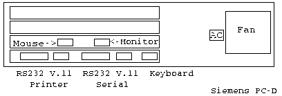
| Video out (Monitor): 1 - N.C. 2 - +12V 3 - N.C. 4 - GND 5 - GND 6 - N.C. 7 - N.C. 8 - N.C. 9 - Composite |
 |
WARNING: Display is at 25kHz Horizontal and 66Hz
Vertical. Typical TV is 15.7kHz Horizontal and 50Hz Vertical. This
usually will not go.
| Mouse pinout (my universal mouse should fit):
1 - Left button 2 - N.C. 3 - Xa 4 - Xb 5 - GND 6 - Right button 7 - +5V 8 - Ya 9 - Yb |
|
| Keyboard port pinout (out means
Computer->Keyboard): 1 - Data IN, Positive 2 - N.C. 3 - Data OUT Positive 4 - +5V 5 - GND 6 - Data IN Negative 7 - GND 8 - Data OUT Negative 9 - +5V |
|
| V.11 ports pinout: 1 - Data IN Positive 2 - +12V 3 - Data OUT Positive 4 - CRS Positive 5 - GND 6 - Data IN Negative 7 - FEIN Negative 8 - Data Out Negative 9 - CRS Negative |
|
| RS232 ports pinout: 1 - GND 2 - TxD 3 - RxD 4 - RtS 5 - CtS 6 - DSR 7 - GND 8 - DCD (NOT IN PRINTER PORT) 15 - SCTDCE (NOT IN PRINTER PORT) - Send clock? 17 - SCRDCE (NOT IN PRINTER PORT) - Receive clock? |
|
| 20 - DTR 22 - RI (NOT IN PRINTER PORT) - Ring Indicator for modem 23 - DRS (NOT IN PRINTER PORT) - Data Rate Selector 24 - TC (NOT IN PRINTER PORT) - Transmitter clock |
http://www.geekdot.com/siemens-pc-x/ - Hard disk version in
blog post.
http://forums.bannister.org/ubbthreads.php?ubb=showflat&Number=102176&page=1
- Look for translated parts of Service Manual.
http://www.duensser.com/pc_fampcd.htm - In some other collection
https://archive.org/details/siemens-pc-d-servicehandbuch - Service
Manual. Part II is mostly about diagnostics software.