|
|
Full source code of ICTester - you can build it in Qt Creator with serial port library installed. I've succeeded with Qt 5.5 in Debian and Windows XP. |
|
|
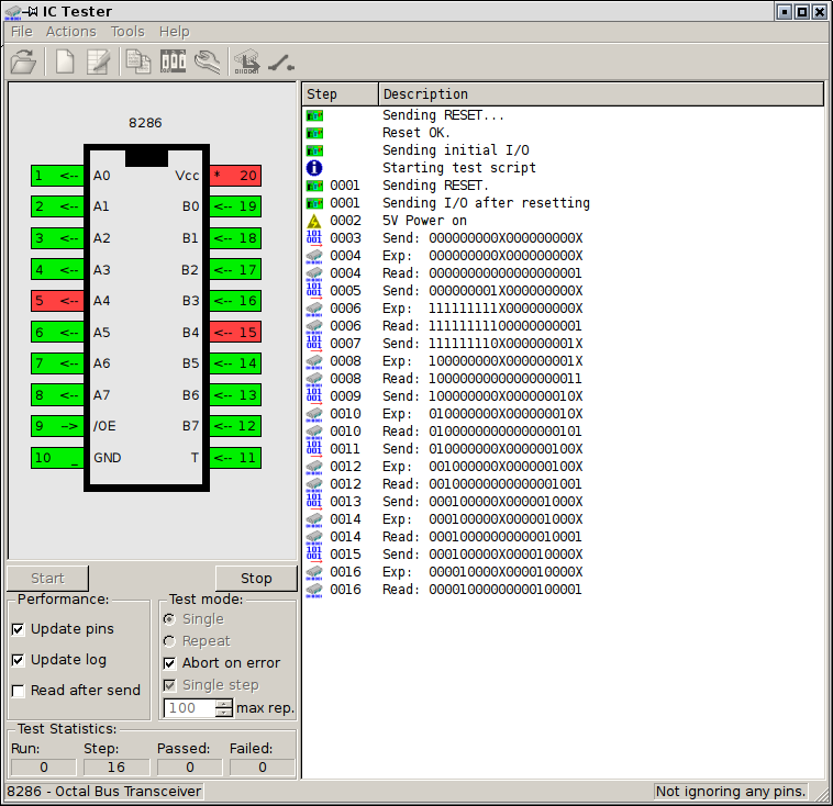
Simple manual |
|
|
Supported chips and where to find test sheets |
|
|
My test sheets - (Updated 20200411) - contains opto817 for optocoupler test. Do not test them for too long as current-limiting is poor. |
|
|
[2020-04-11] Updated romreader.ini with more PROM chip definitions. |
|
|
Windows build 20191028!:
Program,
Qt Library 1, Qt library 2,
Qt Library 3 - extract all of them to single
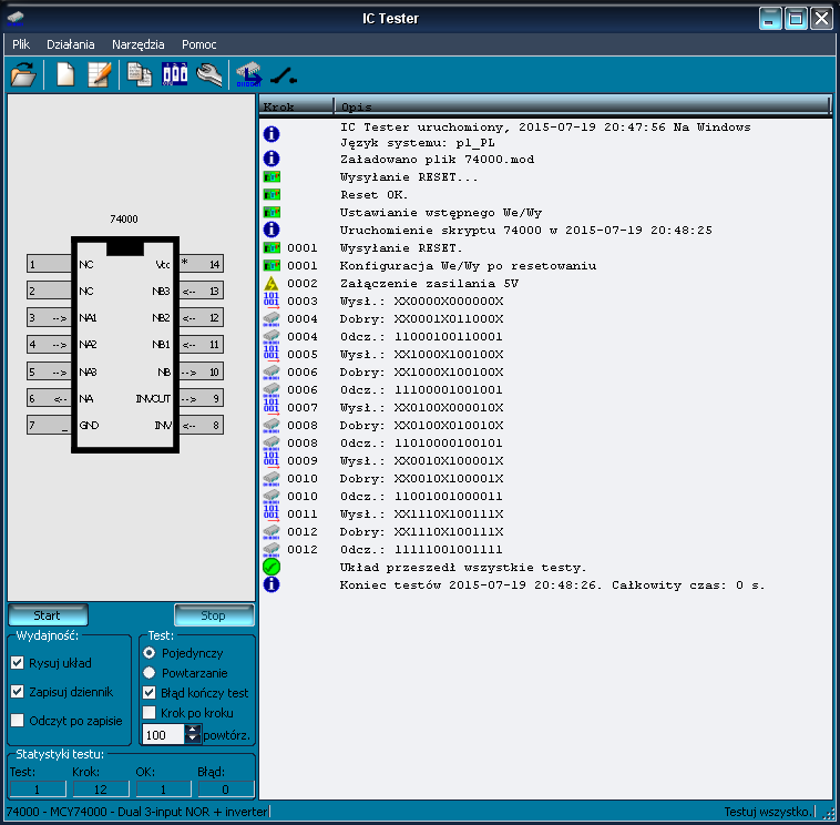
directory. Requires at least Windows XP. (screenshot) |
- Windows build 20150926 (archived): Program,
- Windows build 20150720 (archived): Program
History:
- 20140813 - Initial release
- 20140817 - Fixed old file format opening (x not X)
- 20140905 - fixed bug with NC pin evaluation, added 2 small programs for SRAM testing (6116 and 2114)
- 20141003 - added (E/P)ROM reading console program for: 2716, 2732, 82S129, 74s475, 74s571, K565RT5 circuits. Bugfix in GUI (power editor).
- 20141012 - Bug fixes, ROM reader in command line and GUI.
- 20150105 - Bug fixes, pin ignoring, clock generator and sheet checker, GPL headers.
- 20150125 - 2364 reading support in console and GUI ROM dumper.
- 20150720 - Major ROM reader revamp,
added user-configurable ROM models, advanced ROM reading tests, IC
visualisation has beter display of GND, Vcc and ignored pins, Polish
language support, GUI program command line switches.
- 20150926 - power displayer bugfixes, Chip model detection tool (experimental).
- [20160818] Updated romreader.ini
with 87S185 PROM model,
- [20180810] Updated romreader.ini
with 87S141 and TBP18S030 PROM models,
- 20190702 - Testing series of chips from GUI, 2102 S-RAM testing module, configuration files moved to ~/.config
(program copies settings from older versions).
- 20190703 - Bugfix when series-testing with few repeats. Added Ctrl+Return for start and Esc to stop, Ctrl+O, Ctrl+N, Ctrl+E, Ctrl+I shortcuts.
- 20191028 - Comments support, external tool running, 6810 S-RAM test.
- 20200411 - Bugfix in external tool
launching, 93415 S-RAM chip tester.
romreader.ini ROM models list is in its dedicated
manual part.
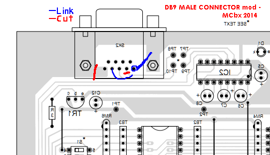
Using male DB9 connector
The PDF states that only female DB9 connector should be used. In
printed circuit board shown in this PDF only few modifiactions
have to be made to adapt male connector. In the picture below you
can see these modifications (view from below - looking INTO
COPPER):
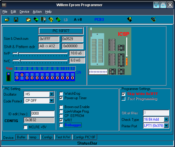
What other PICs?
Today it's not easy to get PIC16F877. Usually you can buy
PIC16F877A which is not exactly the same circiut as it has
different fuse bits. Configurations for fuse bits for PIC16F877A
(tested by me) and PIC16F877 (untested) for Willem programmer are
shown below:
| PIC16F877 (UNTESTED): | PIC16F877a: |
 |
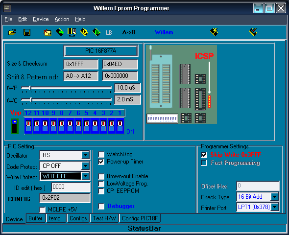 |
Summing up, it's essential to set oscillator to High Speed
External Crystal, WatchDog OFF, Power-up timer ON (ON is
represented as zero).
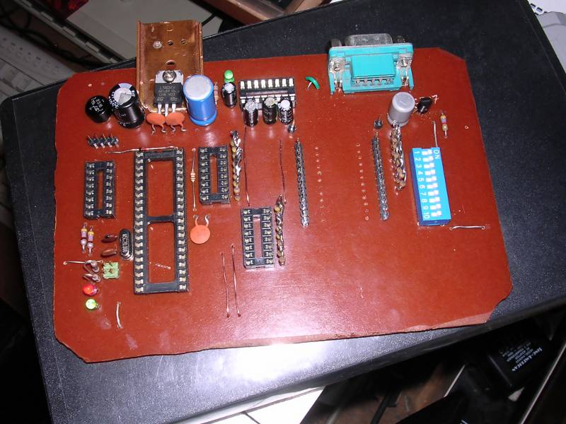
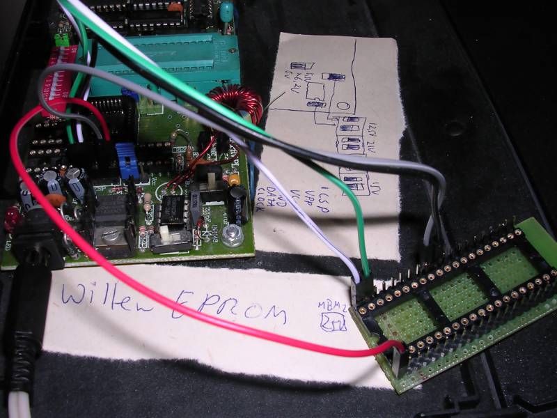
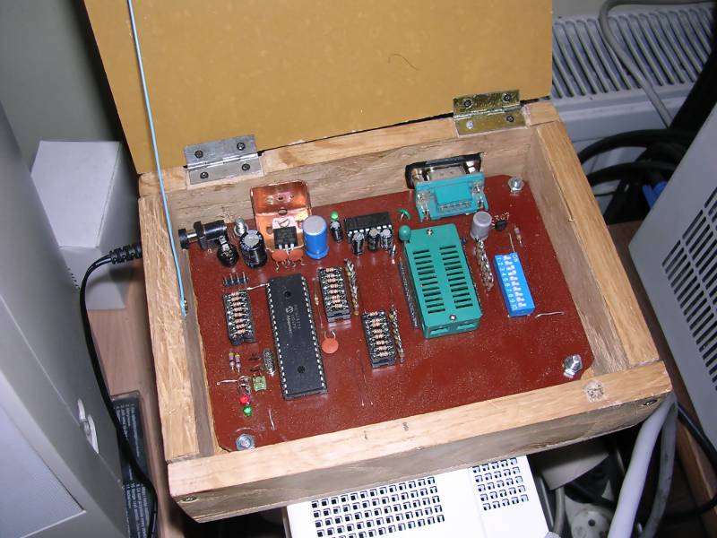
Here are some photos of my tester (BC307 transistor was
successfully used):
 |
 |
 |
 |
| Unfinished PCB | PIC programming socket in Willem PCB3, connected via ICSP pins. | Finished tester in hand-made housing.
|
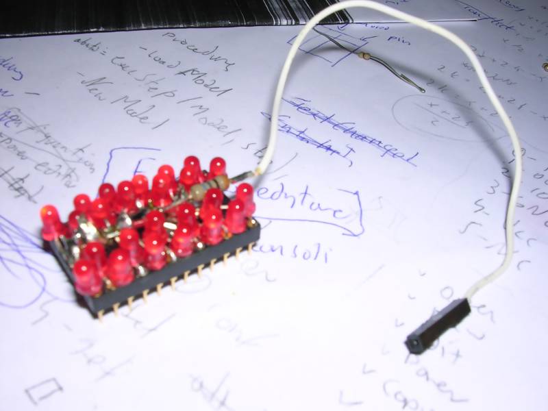
A "Christmas tree" adapter for verifying tester's pins (on sheet with notes from implementing QtICTester). |
End of document
MCbx, 2014-2020.