( photo source: Lorne at the VCFF )
| Home |
|
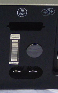
As shown on the left, the case of a very early 5150 is slightly different to above. ( photo source: Lorne at the VCFF ) |
 |
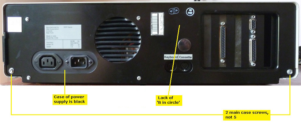
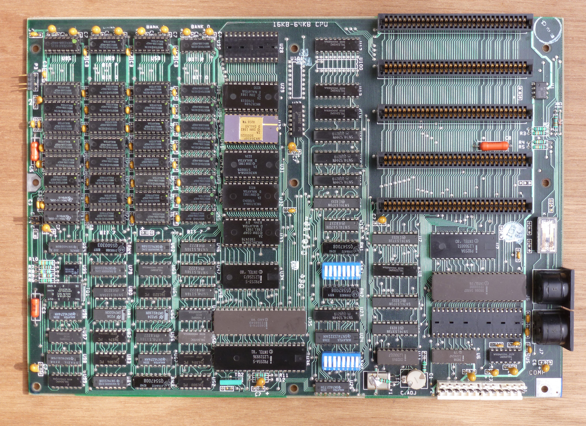
From Framer's very early 5150, which has first revision BIOS. ( photo source: Framer at the VCFF ) |
 |
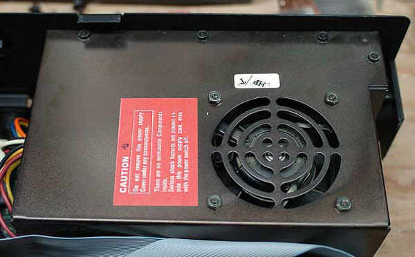
Compared to the above power supply: 1. The fan nuts are now recessed; 2. Different finish. ( photo source: Framer at the VCFF ) |
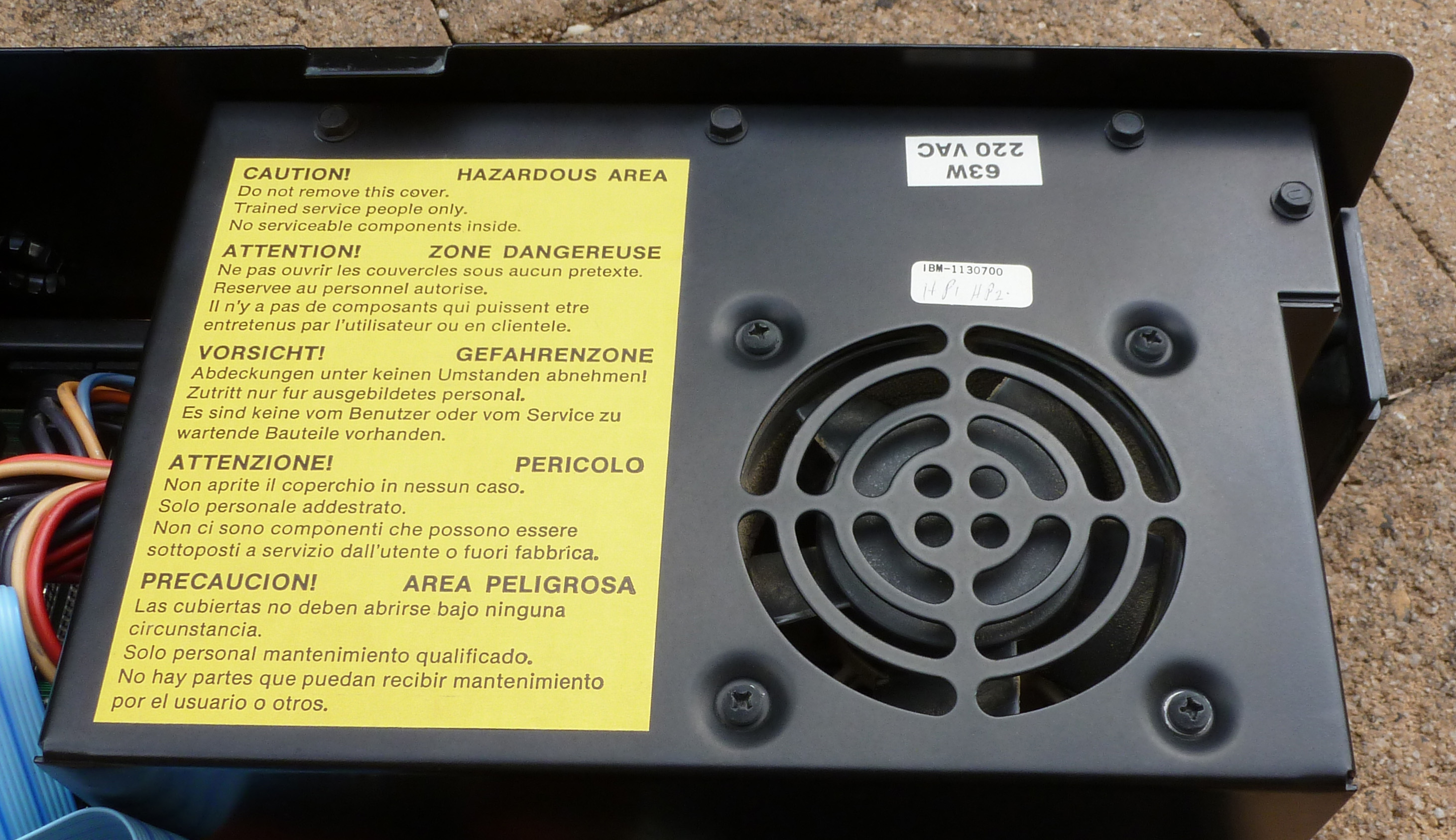 |
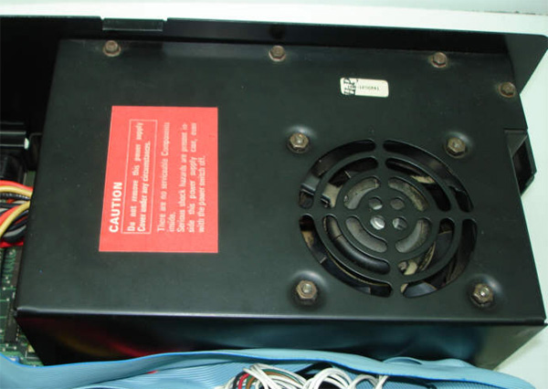
Yellow sticker, and fan nuts moved to inside of case. ( note: This is a 220 VAC version ) ( photo source: modem7 at the VCFF ) |
 |
Click on photo for larger view |
 |
Click on photo for larger view |
 |
Click on photo for larger view |
 |
Click on photo for larger view |
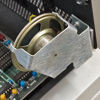 |
From Framer's very early 5150, which has first revision BIOS. ( photo source: Framer at the VCFF ) |
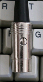 |
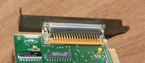
From one of Shadow Lord's early 5150s ( photo source: Shadow Lord at the VCFF ) |