My RasPi Model 100 (a Raspberry Pi in a
TRS-80 Model 100 case)
(Last modified
13 Jun 2012)
The Raspberry Pi (RasPi) is a way cool, tiny, single-board
computer that runs Linux and costs $35 (for the Ethernet-equipped
model). The RasPi will, I predict, become the TRS-80 Model 100
(M100) of its day. I hope it will lead to as wide-spread an
interest in computers and programming as did its earlier counterparts,
such as the M100, the Sinclair Z80, the Commodore 64, and others.
Since the RasPi is so similar to some of those earlier
computer-in-a-boxen, I decided to repurpose an old M100 case as a home
for my new RasPi.
I started with a working M100 I picked up from eBay for about
$25. The unit was actually in pretty good shape. The PCB
was kinda eaten up, since one fad that the M100 community went through
was trickle-charging a NiCd AA battery to act as a battery backup for
the RTC. This usually resulted in leaking of battery goo, which
then corroded the PCB. Luckily, the goo in this case didn't hit
anything vital and the M100 worked fine. It was a lot of fun
playing around with the M100 in its original form; I had forgotten how
much fun you could have typing up Basic programs on your own
stand-alone computer. (Yes, you can do that now on a laptop; I do
it all the time. Not the same.)
When my RasPi arrived, I started the task of replacing the M100's logic
board with the RasPi. One restriction I placed on the project was
to make no wiring changes to the RasPi; if I wanted, I should be able
to disconnect the RasPi from the M100 and have a fully functional,
unchanged RasPi. As you'll see, this requirement added some to
the cost and the bulk of the final project, but I'm happy with how it
turned out.
Please note that this project will likely never be "finished."
What you see here is a snapshot of my progress. Some parts of the
RasPi aren't hooked up yet, and I will likely redo others as my needs
change. But this is a starting point for others who might want to
take on something similar.
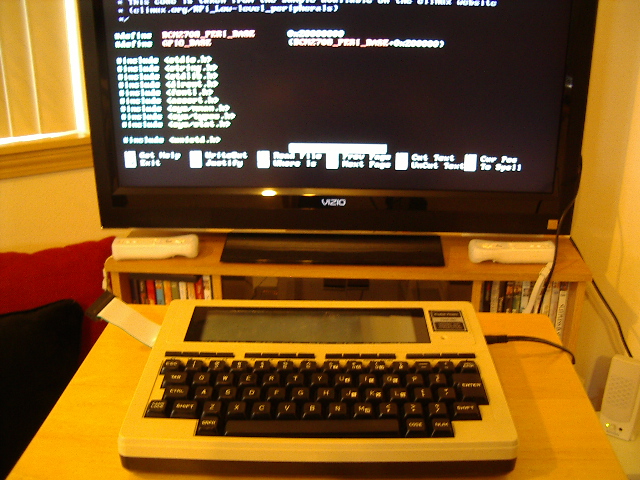
Here is the RasPi Model 100 hooked to my big-screen LCD in the living
room. I've used the RCA video connection from the RasPi to an AVR
input on the back of the set. On the right side of the M100 case,
you can see the power cord from the 5 VDC wall wart used to drive the
M100. On the left side of the case, you can see a 26-pin ribbon
cable sticking out, which is hooked to the RasPi's I/O header.
The screen shows a section of code, in the nano text editor, that I was
working on for controlling an LED hooked to the GPIO pins.
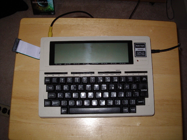
Here is a better view of the RasPi M100. Even though the unit is
on right now, the LCD is dark. That is not (yet) connected,
though I might add some code the the USB converter inside (see below)
to drive the LCD. Put that on my rainy-day list...
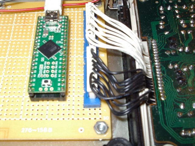
Here is a closeup of the USB converter (Teensy ++ 2.0) and the wiring
to the underside of the original Model 100 keyboard (on the
right). You can find more details on this conversion, including
source code, on this page.
With the logic board removed, all of my added electronics sits on the
metal substrate that is part of the original Model 100's design.
Here, you can see how I've bolted the protoboard for the USB converter
to that substrate.
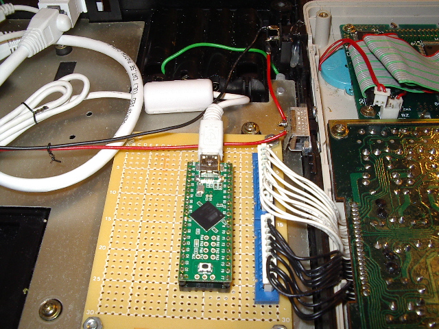
This shot shows the USB converter in the foreground. Above it and
to the right is a slide switch I bolted to the side of the case, for
use as a power switch for turning on the M100. Above the switch
(follow the red wire), you can see the coaxial power jack that I
hot-glued to the side of the case. I wired this connector up for
center-negative operation, just like the original M100, in case I want
to add battery charging later. Although you can't see it clearly
in this photo, I added a 1N5819 Schottky diode in series with the
positive lead on the jack, to ensure I don't accidentally use the wrong
wall wart.
You can also see in this photo the white USB cable that connects the
USB converter board to one of the RasPi's USB connectors. This
provides the RasPi's connection to the M100 keyboard. As I
mentioned above, I chose not to solder wires to the RasPi, opting
instead for plug-in cables for minimal impact on the original RasPi
board.
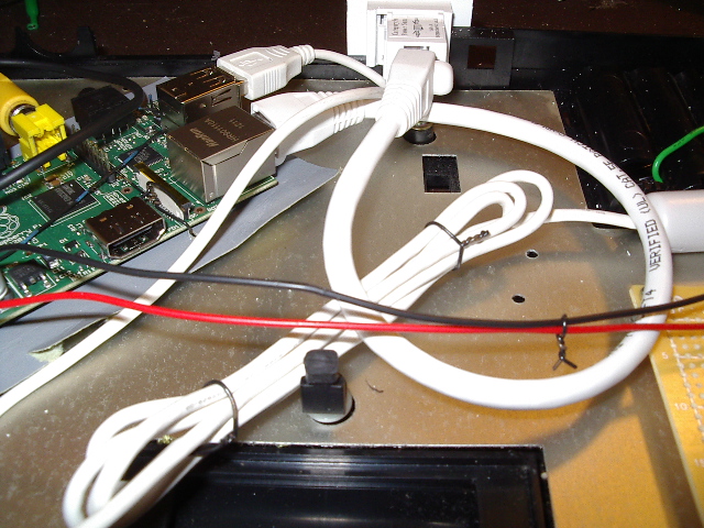
Here you see how I hooked up the Ethernet connection. I cut up an
Ethernet jack wall plate from the local big-box store, leaving the
square hole and a small amount of mounting surface. I then hogged
out a square hole in the back of the M100 case, fitted the Ethernet
wall plate into the hole, drilled a 1/8th inch hole through the wall
plate and case, and locked the two pieces together with a 4-40 screw
and nut. For wiring, I used a 1' Ethernet male-to-male
cable. One end plugs into the RasPi Ethernet jack, the other into
the back of the double-female adapter that came with the Ethernet wall
plate. Again, no cutting or soldering of the RasPi board...
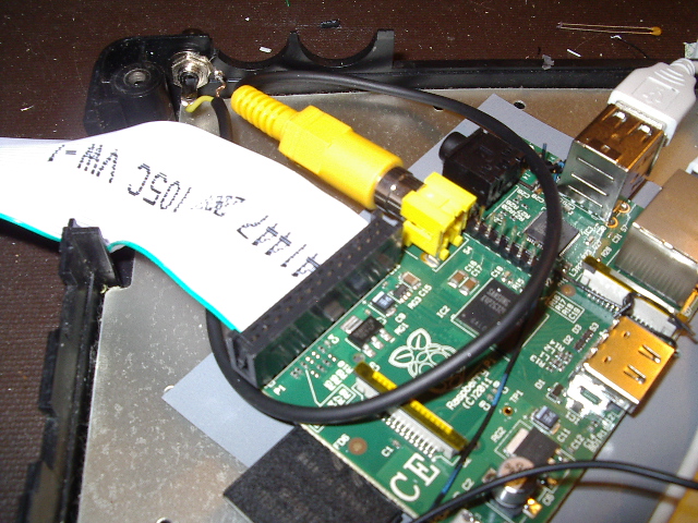
This photo shows the large ribbon cable hooked to the GPIO header; the
cable is routed through an existing hole in the side of the M100 case.
For the video, I drilled a 1/4-inch hole in the back apron of the M100
case, then mounted an RCA jack in the hole. I cut one end off of
a scrap RCA video cable and wired the free end to the RCA jack. I
then plugged the yellow RCA plug on the video cable into the RasPi's
composite-out jack.
A future mod is to attach an HDMI-to-DVID adapter to the RasPi, then
repositon the RasPi so I can get access to the DVI-D connector on the
back apron. For now, the composite output works fine.
Note in this shot how the RasPi board is mounted on the metal
substrate. Since the RasPi developers chose not to include mounting
holes (wth??), I tied my RasPi to a cut sheet of plastic-coated paper
using insulated wire, then used foam-tape to fasten the paper and RasPi
to the substrate.
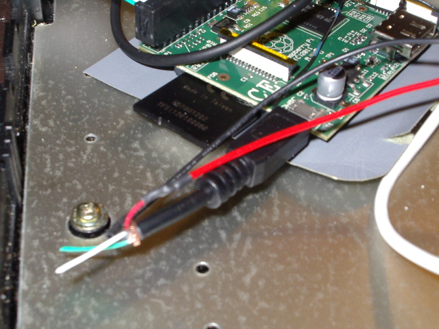
Finally, here is the power connection from the other end of the M100
case. I sacrificed a USB cable with a cell-phone charger
connection (micro USB) so I could hook up the red and black wires from
my coaxial power jack.
Summary
So that's the current state of my RasPi Model 100 conversion. I
have to say, this thing is more fun to use than I was expecting.
The boot time is obviously longer than a real M100 (something like 20
seconds versus zero), but when you hit the login prompt, you have a
full Debian Linux system in front of you. And having a
full-travel keyboard mounted to (actually, around) the RasPi makes a
big difference. I was keying in the code for the LED program
above and realized at one point that this was really fun, that the act
of typing code on the target, compiling and running on the target, was
really fun. I no longer need a host PC, filled with compilers and
linkers and IDEs, to get code onto the target and actually run it.
The RasPi is a great little board. Put it in a classic case like
an M100, and you have a Linux system that is fun to use and makes a
great platform for learning, be that Linux or C or Python or...
Home


