Chapter 4: Mainboard
Mainboard inspection
If there is one mainboard. If there are many boards, try to distinguish which one is
responsible for what part. Looking at the board, notice any missig chips and
modules. If the computer has been opened before, they may not be upgrade
sockets. but missing chips. Now check condition of electrolytic capacitors -
bulged, leaking or damaged capacitors may have to be replaced. In East German
computers I usually see small blue axial electrolytic capacitors, and in most
cases they are damaged. Larger blue capacitors are quite acceptable.
Does mainboard contain rechargeable battery? If yes and it is not leaked,
consider removing it, because it may leak any time. If you see a white
powder-like substance on or near batttery, remove it immidiately. Mark only
where + and - were. Look for blue or green-coated PCB tracks, they may need patching
with a wire.
When battery leaks, the corrosive compound condenses on external battery casing
and all components nearby. This chemical causes rapid oxidation of PCB's copper
tracks and if a PCB has more than 2 layers, may damage the board irrecoverably
oxidizing tracks between laminate layers.
After battery is removed, remove the sticker from battery. Sometimes it
is more convenient to cut it off with a heat-shrink tubing which keeps battery
in one piece. Glue this sticker somewhere near battery place because later you
may need to replace it.
Cleaning the mainboard
Usually a typical brush (use a clear one, without paint) is enough. Sometimes
old toothbrush may be needed if the dust is stubborn. If you really need to
clean it, you can use small amounts of window washing liquid - but don't let it
in capacitors. Some people e.g. in
Arcade Otaku Wiki
use water to clean PCBs or even use dishwashers. Avoid it. Maybe it's good for
arcade machine mainboards, I don't know, I haven't any, but water may damage the
following components in a typical microcomputer mainboard:
- Wax-coated ceramic disc capacitors (most flooded machines I got had them
damaged)
- Crystal oscillators (especially pre-1985 ones, these cans are not so
hermetic)
- Smaller electrolytic capacitors (if they're not hermetic)
- Soviet ICs
- Some specific types of plastic, e.g. one used in Siemens lever-like
"DIP-switches".
- The "glue" used to stick thin wires used in some mainboards to the PCB
surface.
- And of course stickers.
Capacitors
Carefully look at the capacitors. Are there any capacitors that
look like small shiny drops and they have "+" or "-" pole marked? These are
tantalum capacitors and they like to burn. The problem with them is that
their conducting tantalum layer grows sharp crystal towards insulator finally
making a hole in it. When it
shorts, the capacitor emits smoke, sometimes even lights up for a tenth of a
second. To avoid this problem run with an ohmmeter around power tracks and check
for shorts. Later for some time have an eye on the working mainboard. If few of
them blown up, replace them, there should not be any more damages in the
mainboard, and maybe power supply's fuse may blow. However, if power supply is
powerful enough and has no protections, it may use copper tracks as a fuse
burning them. So after replacing faulty capacitors verify power of the most
important circuit. Don't forget to check what comes from the power supply unit,
as when DC has a ripple by bad capacitors in a power supply unit (seen on a
typical cheap multimeter as dramatically lowered and unstable voltage), the role
of eliminating ripple is in capacitors in mainboard.
When the most urgent operations on mainboard have been made, analyse the
computer's parts. Most microcomputers consist of similar blocks, only models,
structures and manufacturers are different. Identify CPU chip, or chips, RAM
chips (is it static RAM or dynamic one?), ROM or EPROM, if permanent memory like
EPROM is in socket, consider archiving it in a programmer if you have one.
If you don't know what system does the machine run, you can make some
assumptions here. If a CPU is Z80, machine has larger (>32kB) amounts of
RAM and floppy disk controller is built in, it may be a CP/M machine. If
it has a large ROM, it may contain much software or diagnostic subsystem
on it.
Computers with MOS or Motorola circuits have really different
applications and design. The characteristics of such machine should be
figured out from peripherals connected to CPU.
Datasheets of integrated circuits are useful here.
Identify VLSI circuits. They are usually in larger packages, 28-pin EPROM-like
(but without a window) or 40-pin. They are for supporting different capabilities
of microcomputer. For example, 8255 is a parallel interface, so look what is
function for its outputs. Maybe expansion port? Or maybe keyboard?
Identify glue logic TTL chips (usually 74xx family) or glue logic proprietary
chips. Having identified "black boxes" may be needed in future repair.
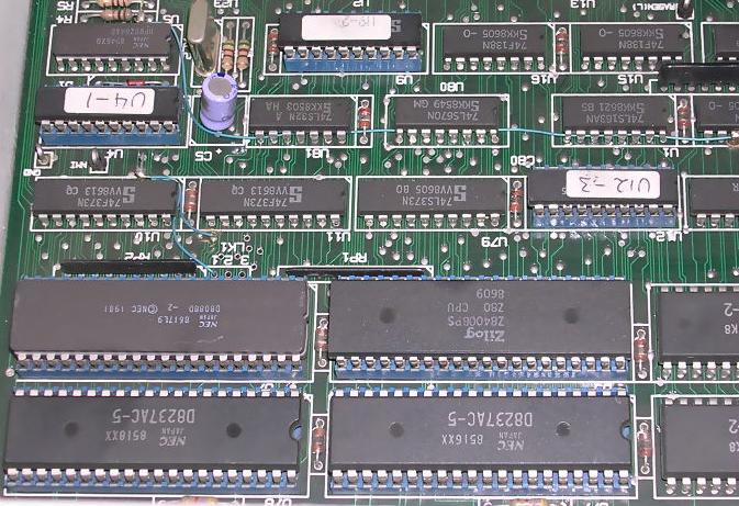
Try to find the picture generator. Lack of picture generator VLSI chip
means that the computer has just some video memory whose contents is
inserted to screen by CPU or logic. Dedicated circuit allows to discover
graphics capabilities of the computer. |
And this microcomputer contains two CPUs: Z80 and 8088.
It may run DOS or CP/M. |
How about sound output? mainboard may contain a small piezo
buzzer or may have a speaker connector. In home computers sound output leads
right to modulator or there is sound output in monitor connector. Is there any
sound-generating chip?
And the modulator. If it is in its metal can, it is probable
that it's good. If someone messed with it, there is a problem, because it is
hard to recover its coils.
Try to identify expansion slots. This way you may find floppy
drive connectors, different inputs and outputs. On the other hand something
which looks like ISA slot may not be an ISA slot, and definitely isn't ISA slot
if it's present in a non-PC machine.
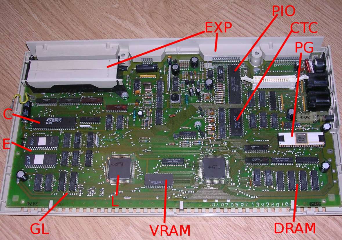
As an example, below you can see a mainboard of Robotron A5105
with description of various circuits:
 |
Where:
- C - CPU - Z80 chip
- E - two EPROM chips storing relatively large amount of data
(27256 and 2764 chips). Probably programming language or operating
system. Probably 2764 contains character data.
- GL - Glue Logic made on TTL 74xx chips
- L - one of two proprietary logic gate arrays. It means that the
computer was manufactured in quite large number because production if
such arrays in small amounts is expensive.
- EXP - Expansion connectors. Proximity of one of connectors to the
CPU suggests system bus expansion.
- VRAM - A small static RAM chip suggests that it's the fast video
RAM, but it may be some buffer memory too.
- DRAM - Few chips of dynamic RAM can be the system RAM. You can
count how many kB of RAM the system has.
- PG - Quite advanced picture generator chip. This computer was not
an ultra-cheap system.
- CTC - Timer chip for Z80 computer system. Maybe the machine has
serial port or sound generator?
- PIO - Parallel Input/Output chip for Z80 computer system near
keyboard socket suggests that the keyboard is read from its pins. Some
of them are connected to expansion ports too.
Notice the lack of crystal, which is usually present, it means that the
computer is driven by an inverter-based oscillator. |
It means that the machine is a Z80-based machine with 64kB of
RAM, with ROM containing some large program, so after powering up it should
display something on screen. Good graphics capabilities place this machine as an
educational or engineering computer. Input/output capabilities allow to expand
the system bus and use the cartridges. And notice the DIN sockets, it looks like
there may be a tape in/out, monitor output, but there is no modulator. Lack of
modulator usually means that it was not designed as cheap and easily accessible
home computer (as home computers were usually connected to TVs).
Exactly as in Robotron A5105
description (except memory architecture which indeed is quite different).
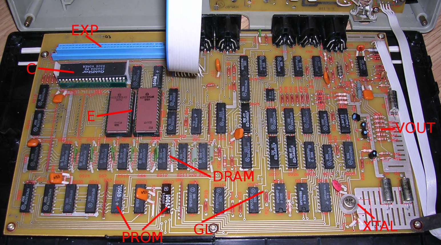
One more example of mainboard inspection:
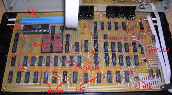 |
Where:
C - Z80 CPU
E - two 2764 EPROMs
PROM - Pre-programmable ROM chips. When they fail, it will be difficult
to repair.
DRAM - 64kB of dynamic RAM.
GL - Glue logic, everything is made with 74xx chips
XTAL - 7.5MHz crystal. This Z80 won't work with so high frequency, so
dividing by 2 we'll get usable 3.75MHz.
VOUT - Quite scarce video output, divided to 3 subcircuits with their
own transistor-based amplifiers/converters. Probably RGB with unknown
signal levels.
EXP - Expansion connector, proximity to CPU tells that it is probably
system bus expansion.Notice DIN sockets, probably both for power
input, video output, tape in/out and more expansions. Proximity and
connections of two separate DIN sockets near keyboard suggests that they
are joystick or keypad connectors. |
So here we have a simple Z80-based computer, with quite large EPROM (probably
containing programming language interpreter, so it should display something on
screen when turned on, 64kB of RAM and most logic made on 74 chips. PROM
suggests adding some encoding capabilities, they could be used to add
functionality which couldn't be easily added with 74xx logic. Video output is
probably RGB, so it's a color display. Maybe a ZX
Spectrum-like computer?
Exactly as in Orel BK-08
computer.
To estimate age of the computer, look at chips. TTL logic chips and
some VLSI have date codes. Codes are usually 4 digit numbers with smaller font,
located near chip markings. The first 2 digits are usually year, e.g. 89 means
1989. Next two digits are number of week in this year in which chip has been
made. So if you see "8640" it means that the chip has been manufactured in 40th
week in 1986. By looking for the latest chips and making sure that the chip has
not been replaced, it is possible to estimate computer age. For the week code,
just know that year has 52 weeks so it cannot be larger.
The main goal in this stage is to prepare for making a "verification
system": a minimum-configuration of the computer to run it and test does it
work and may all other peripherals be connected. Usually Computer, keyboard,
monitor and sometimes nothing more.
MCbx, 2016