Chapter 6: Keyboards
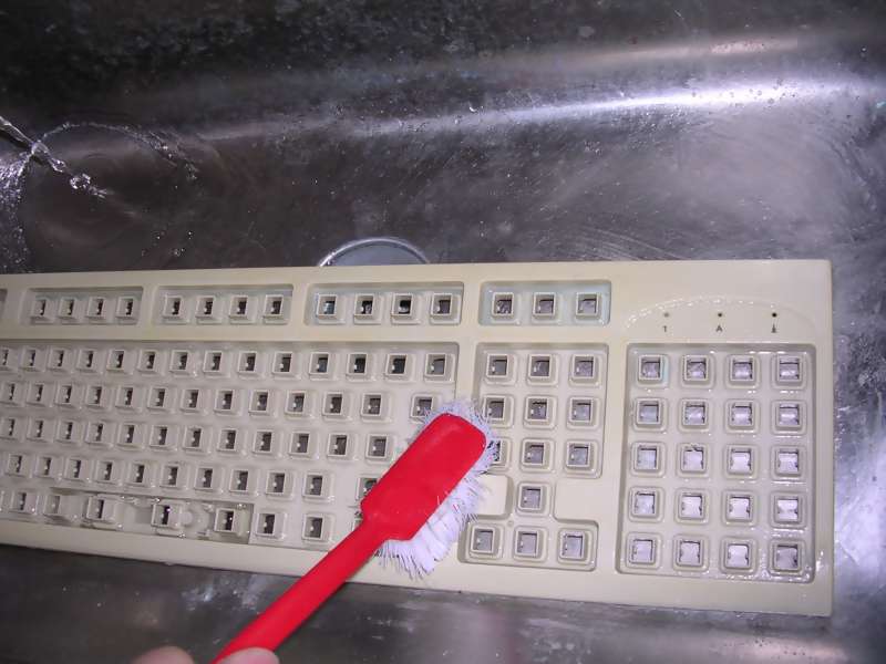
A method for cleaning keyboard's keycaps is similar as with other computer parts, but I just put them to bowl of
water, add some washing powder (only for moulded keycaps, for printed ones
normal dishwashing liquid is enough) and stir them using a brush on longer
stick. After quarter or 2 they are clean and can be rinsed and dried (put them
to old pillowslip, put on warm surface and move from time to time). In the
meantime it is usually needed to remove layers of dirt from the
keyboard's base plate.
Keyboard mechanism itself (contacts) should be disassembled if and only if there is a problem with
it. There are many designs and constructions and there may be a problem if it
falls apart. There are few types of keyboard mechanisms:
1. Magnetic relay (reed switch)/hallotron based keyboards (e.g.
Elwro 800
Junior,
Meritum, many Eastern-block computers)
Pressing a key moves a small magnet towards Hall detector or reed switch. In
most constructions they are soldered horizontally to base PCB. Problems may
include broken reed switch, missing magnet or broken solderings. Some Italian
computers use vertically mounted reed switches, they fail mechanically (glass
tube cracks) very easily. Remember that if you want to desolder reed switch, use
solder pump and don't bend tube connectors as they may break off with tube.
These keyboards are quite durable and hitting keys usually doesn't lead to
excessive wear of contacts.
2. Mechanical switch keyboards (e.g. early PCs,
Robotron 1715)
Keys move switches which mechanically join contacts. The most typical problems
are broken solders, sometimes even broken tracks if someone slams the key too
hard, in rare cases the switches themselves need replacing. It is generally
impossible to disassemble it entirely as switches are directly soldered to PCB.
You can identify it by removing a keycap - switch will be shown, or
seeing a PCB from below, in this case you will see lots of soldered
switches, sometimes centered using a bolt in hole.
The problems are fixed by replacing single switches or fixing broken PCB
using a soldered wire.
Remember that some very old keyboards (1970s or so) may have an old,
mercury-based switches, so be careful while trying to disassemble a
switch. Most keyboards from early 1980s and later have normal,
mechanical switches.
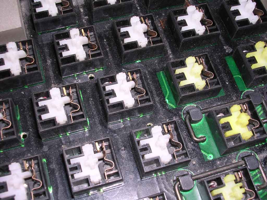
You usually won't be able to remove the plastic base plate without
desoldering all switches from the PCB. |

Two types of mechanical keyboard contacts |
Source:
Wikipedia |
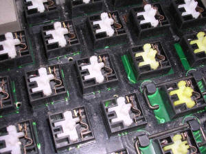
3. Conductive track (e.g.
Atari ST)
PCB is still used, but contains normal tracks (covered with masking lacquer) and
exposed gold-plated contacts, usually as concentric spirals or ladders. Key
presses a carbon-coated rubber connecting gold-plated contacts. In some rare
cases slightly concave metal discs are used. If this keyboard doesn't work, PCB
has to be removed and cleaned using denaturated alcohol or IPA. Then using soft
cloth dipped in alcohol, every conductive rubber has to be slightly cleaned.
Don't wash the conductive layer off the rubber. During disassembly it is
essential to keep the rubbers in their places. They may easily fall apart.
It may not be exactly conductive, but sometimes it forms a capacitor, so
checking with ohmmeter may not give results. Generally capacitive
keyboards have silver contacts looking like alluminium foil. |
4. Conductive mat (e.g. some IBM
PCs)
Similar as 3, but there is a piece of insulation with holes in places of
gold-coated contacts. On it, there is a conductive mat. Key presses the piston,
which presses the mat to contacts. Because mat may be fragile, it may be pressed
not directly with piston, but with spring buckling smaller hammer. This
technique has been used in some IBM's keyboards. Such keyboard cannot be easily
disassembled as hammers will fall off, but is quite durable as key pressure is
not directly transported to contacts. A nice description and illustration is
shown in this Wikipedia
page.
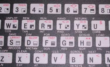
5. Membrane with keys printed-in (e.g.
Videopac G7000,
ZX81)
Two layers of conductive foil are divided by matrix with holes. On this
sandwich, another layer with printed keys is placed. Keys are not pressed very
deep, usually it is needed only to press the foil sheets toegther to
make a short. Sometimes 3 layers are used, simulating pressing 2 keys.
These layers are separated by two sheets of foil with holes. Pressing a
button causes two topmost layers to be shorted first, then bottom of
second layer shorts with the lowest layer.
Is is very hard to repair
such membrane, because the conductive foil cannot be soldered (melts in lower
temperature than solder) and it easily breaks. It can break near frequently used
keys, in ribbon cables or printed layer may just wear off and break in
pressed areas.
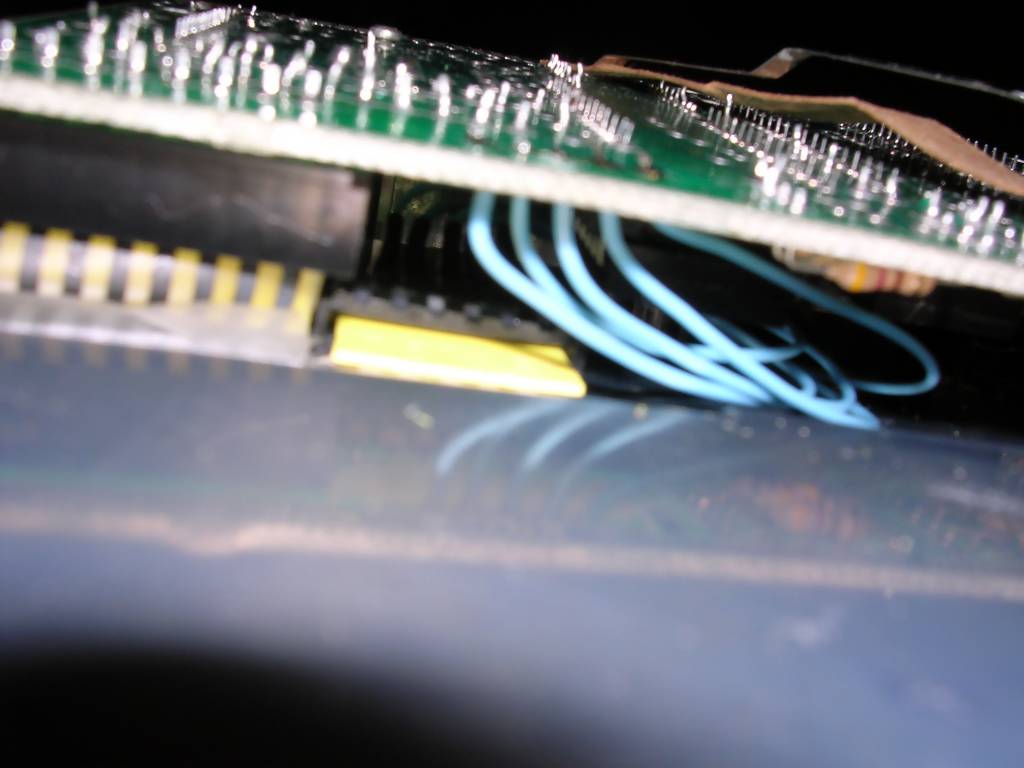
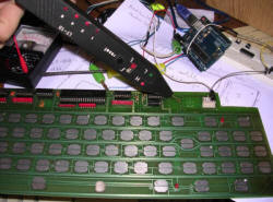
If the ribbon cable is broken, it can be cut and, using a socket,
patched with another cable. For example in ZX81 only about 1cm of good
ribbon left, the rest was damaged by crack. I decided to unsolder the
socket, glue it to the bottom of the casing near the end of a ribbon and
plug the remaining ribbon to it. Next, wires were used to connect socket
to its place on the mainboard. Repair was successful. Such repair is
shown below: |
 |
 |
6. Membrane with separate keys (e.g.
ZX
Spectrum Plus)
As above, but with solid plastic keys pressing the membrane. Repairs are also difficult
because it ends with the same membrane. This
keyboard is the most popular in later PCs (mid-1990s and onwards). If the keys
are made of rubber, like in ZX Spectrum, bad membrane can be replaced
with thin PCB and conductive rubbers may be added to the rubber part.
Such DIY membrane for ZX Spectrum has
been made and works well.
In these keyboards 3-layer version is commonly used so it is not so easy
to make the substitute using thin PCB etching. |
7. Membrane with rubbers (e.g.
Amiga 500)
A mix of 6. and 3. Single foil with tracks, exposing gold-plated contacts. Also
hard to repair.
Of course different computers usually have different types of
keyboards and connecting e.g. robotron PC1715 keyboard to robotron A5120 is not
a good idea (leading to permanent keyboard malfunction) even if their plugs are
the same. Common PC keyboards have DIN plugs, and they are usually not
compatible with 8-bit microcomputers with DIN keyboard connectors. About PC
keyboard - there are 2 standards, XT and AT. It's better to have keyboard with a
switch allowing to change mode.
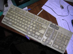
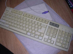
Cleaning and restoration
Washing the keyboard
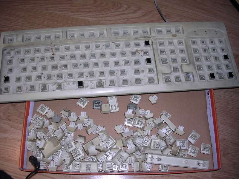
Some people wanted me to describe this. Mostly for "keyboard soup" pictures
probably :).
First, check two things which prevent this procedure:
1. If printing on keys holds poorly and falls off, do
not do this.
2. If you cannot remove a key in a reversible way, i.e. you cannot put
it back, definitely do not do this. Old plastic in keyboards may become
fragile and latches may break. After this procedure, the plastic may
even become more fragile. If you have such fragile keyboard, the better
cleaning method will be to use a small paintbrush first to sweep all
things from under keys and then cleaning with wet cloth using something
flat to go between keys.If the painting holds on keys well (or they
are double-moulded keycaps) and it is possible to remove and put back
keys without destroying, you're good to go.
Avoid removing spacebar. In some keyboards, these long spring-wire clips
may require some precise tools to be set again. Do not break their
latches as they are fragile. Generally remove these large/wide keys at
the end, having lots of space around.
|
 |
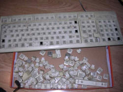 |
The procedure in fact is simple, and can be described
the following way: Disassemble, wash, rinse, dry, reassemble. However,
as many things may go wrong, take as many photos as you can to put parts
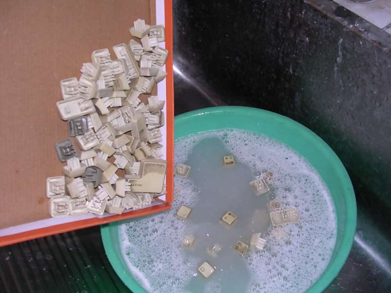
back as they were originally. 1. Remove keycaps and store them in one
container. All other accompanying things like springs, plastic tubes or
latches go to another container. They may be cleaned with a brush,
alcohol or window-washing liquid if they are extremely dirty, but they
rarely get as dirty as keys.
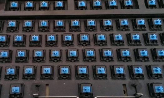
2. If possible, remove top cover for cleaning. This is usually safe when
you see that keys are on a plus-like or minus-like contacts, or have a
square plastic tubing with rubber membrane visible below (late 1990s),
but I would avoid doing it to some older spring-buckling IBM keyboards
(late 80s/early 90s) as this may fall apart really badly. |
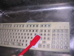
3. Clean the cover. Separated cover can be cleaned in
running water, even with dish washing powder and some brush.
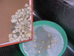
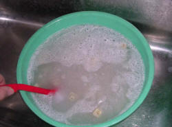
4. Now the keys. Fill a bowl with warm water, add 1-2 teaspoons of
washing powder, put keys in, slowly mix with brush to make keys "click"
against each other. For a typical dirt resulting from using and storage
in normal conditions this is totally sufficient and after 10 minutes you
will get quite clean keycaps.
5. If keys are still dirty, take a few keys by hand and clean with brush
in water, then repeat.
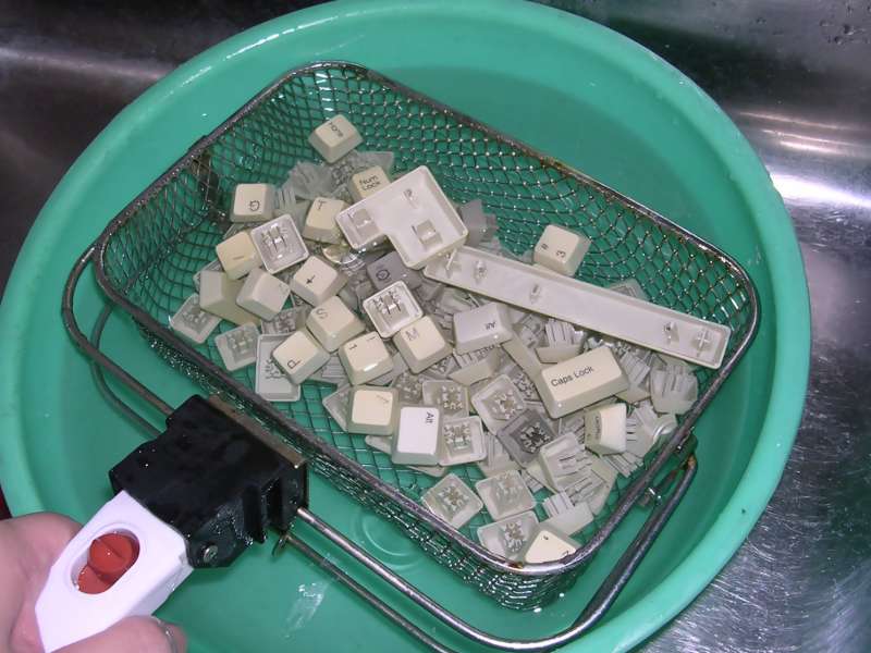
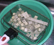
6. Whent hey are clean enough, remove all keys to another container.
Preferably something with small holes like an old sieve or colander. I
use an old metal basket from decomissioned deep fryer.
7. Check one more time that no keys or their parts were left in water.
Water after washing is not transparent anymore, so empty the bowl slowly
and preferably through drain holes smaller than key or their parts.
Sometimes wide keys have a plug-in guides for metal parts - it's better
to make sure that all of them are in place. |
 |
 |
8. Rinse the bowl, fill with new water, rinse the keys
by moving them the same way as washing.
9. Repeat the procedure a few times, this is important as the key may
loose smooth move if not rinsed well.
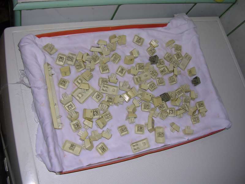
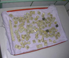
10. Put keys in old pillowslip or just wrap in old cloth, move them a
little for some time to remove excess water, change the cloth. Do it a
few times.
11. Because in the smallest parts there is still water, dry keys for a
few hours in a sunny day or ca. 2 days in room conditions.
12. Re-assemble the keyboard. |
Repairing reed switch / Hall detector keys:
In fact, there is not much to break in them. Check is magnet in right position
and is the reed switch not broken, if anything is broken, replace. In silent
environments you can slowly press the key and listen for "click" of the reed
switch to check it. Most pushing force is directed not to contact, but right to
base board, so these are durable. Reed switches contacts display no mechanical
fatigue, as their deformation is just too low. They however have glass casings
so they may break when really too big force is applied, e.g. keyboard is thrown
with switches exposed. While replacing reed switches do not try to bend their
pins holding only the glass envelope as this will break. The proper method is to
hold (with pliers) a pin right near the envelope and bend it on the other side.
When desoldering a working reed switch, use some pump or wick to remove alloy
and then take the switch without bending pins.
Restoring mechanical contact switches, if the contact cannot be disassembled,
goes in the following order of fixes:
1. Resoldering the contact to base PCB.
2. Blowing compressed air inside, through the "key shaft" pressed in.
3. Spraying with contact cleaner (usually IPA, Isopropyl alcohol) with keycap
removed, it should flow inside, then press it lots of times, wait until
evaporates.
4. If all else fails, replacing contact.
I have not found effective method for repairing these transparent foil keymats.
When tracks are broken, it's impossible to solder them as melting point of foil
is too low, maybe conductive, silver paint? They are so fragile that some
liquids (like wine for example) may dissolve them.
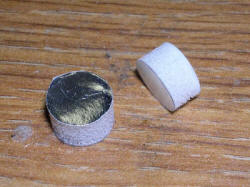
Restoring the capacitive keyboard contacts
You usually have to re-build the contacts. Contacts are
round "sandwiches" which have following layers:
1. A stiff plastic locking the contact in key plunger.
2. A few millimeters of sponge as a buffer.
3. A very thing conductive layer as capacitor's layer.
4. An insulating layer as capacitor's insulator.
So they are not electrical "contact" like in a switch, but capacitive
contact, as printed circuit board's tracks contacting the insulating
layer with conductive layer behind work as capacitor, passing only some
higher frequencies. This may look complicated to detect and generate at
first, but technically many times an ordinary multi-bit binary counter
chip is used to generate different frequencies (even shift registers can
be used). Some op-amp nearby amplifies weak signals passed through
capacitance enough to measure their timings by the microcontroller and
know which frequency has passed through which contact. |
 |
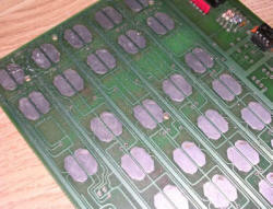 |
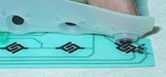
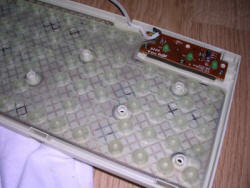
Unfortunately when the capacitive pad breaks, it is
needed to make new "sandwiches". It is hard to salvage something, as
usually the sponge is worn, the conductive layer could break in half and
stiff plastic has remains of sponge on it. If the contacts on PCB are a
bit worn, as in photo on the left, it's still usually not a problem.
This requires some specific materials, I will try to describe what I
used successfully and where to get them:
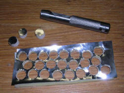
1. The must-go tool is a hole punch with specific diameter, like
the diameter of existing contact. In many PC keyboards it's a bit more
than 10mm, a bit larger in old, 1970s terminal and totally different in
some early Apple machines. Too small punch will result in contacts
falling off plunger, too large and they will not fit. The "contacts" are
held by this stiff plastic springing with usually 2 latches - the
plastic inserted there springs and just pops in them. Another tool is
something longer and sharpened to pop the plastic parts off these
latches and push them in. May be a jeweller screwdriver, some needle on
handle or dentist's metal tooth pick. Generally this should be thin and
narrow enough to go under the stiff plastic disc when held in plunger. |
2. The stiff plastic. I found the transparent
plastic for bound documets cover totally sufficient. With one sheet you
can do many pieces.
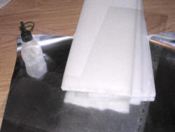
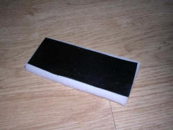
3. The sponge. Not these closed-cell foam, but the sponge which
can be compressed and acts as a buffer for key pressed in. You need a
proper thickness. Too thin and layer will not reach the contact on
circuit board. Too thick and it will contact a whole time. I found in my
keyboards it was a bit smaller than 5mm. The best way is to have a
proper thickness measured from old parts (use these which have sponge in
one piece). If not, read further, but be careful with the process of
reducing thickness.
4. The capacitive layer. Test different foils, it must be silvery
and not conductive (check with ohmmeter) - it means that the aluminum
layer is there, but is coated with transparent insulator. To test an
unknown material in keyboard's printed circuit board, do not put a whole
sheet as this will not work, but cut a rough circle of more or less
proper diameter, put it rather with some plastic tools instead of
fingers as fingers also have some capacity, and monitor does the
keyboard register the keypress. I have successfully used the following
things:
- A foil used to seal juice boxes, it is conductive on one side and
insulating on the other. The problem is that it's small, you can make
only 2 round "sandwiches" from one juice box.
- A foil used to store food on delovery. Generally "plastic foil -
aluminum foil - paper" composite. Works beautifully and may be present
in large quantities in a pizza on delivery. That's where I found my
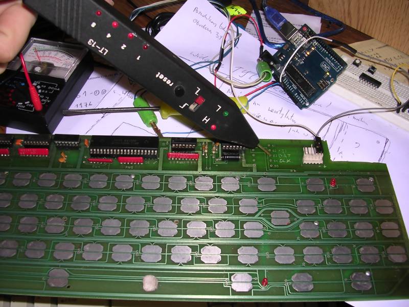
foil.On the right you can see testing method for capacitive layer
with PC XT keyboard and TTL probe. The probe is set on Clock line, and
the pads are put to contacts. Change in counter of probe (or generally
blinking of LEDs) means that the contacts has been detected. This will
not always work as some keyboards may need initialization, so computer
or some interface has to be used for checking. |
 |
 |
Now reducing sponge's thickness. Do not reduce e.g.
20mm to 5mm this way because you will produce too much toxic substances,
but I have successfully reduced 8mm to 5mm in a small, 4x10cm square. My
problem was that the commonly accessible sponge used for packing fruits
(the advantage: it was free) was about 8mm thick, so I cut a small part
of it and removed layer by placing it on a hot, flat surface. The sponge
is then removed from plate right when decay is visible (it will mostly
progress for some time a bit more) in form of dark-brown powder. This
MUST be done outside, in well ventilated environment as with high
temperature the sponge will (a) transform to brown powder and (b) emit
toxic fumes. Use something not extremely hot (I used an old cloth iron
mounted with its flat surface upwards) as above 300-350 degrees Celsius
this reaction may make World War I - grade poison gases (sometimes
called "yellow smoke"). Now it is needed to glue it together. What I
found:
1. Sponge to plastic may be freely sticked using neoprene glue, not a
thick layer, with small pressure applied. The neoprene glue will make
the plastic more durable.
2. Capacitive layer to sponge may not stick to it nearly at all with
neoprene glue and some more penetrating glues may deform the sponge. I
used a thin two-side sticky tape (the thinnest version, in fact a foil
covered with glue on both sides).
This "raw material" is then used to produce, using hole punch, these
"sandwiches". These sandwiches just work in my keyboards well. |
MCbx, 2016-19